Salford 570 RTS Series User manual

TILLAGE
SPECIALISTS
S
A
LFO
R
D
570 SERIES
RTS
ASSEMBLY MANUAL
13, 24, 27, 30, 41ft.


TABLE OF CONTENTS
Frame
Axles
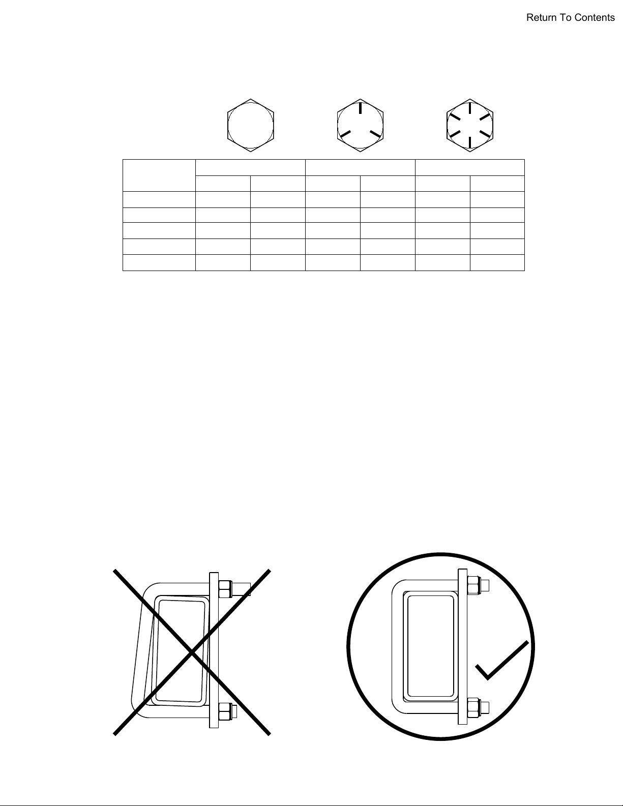
Torque Recommendations & U-bolt Instructions..........................................1
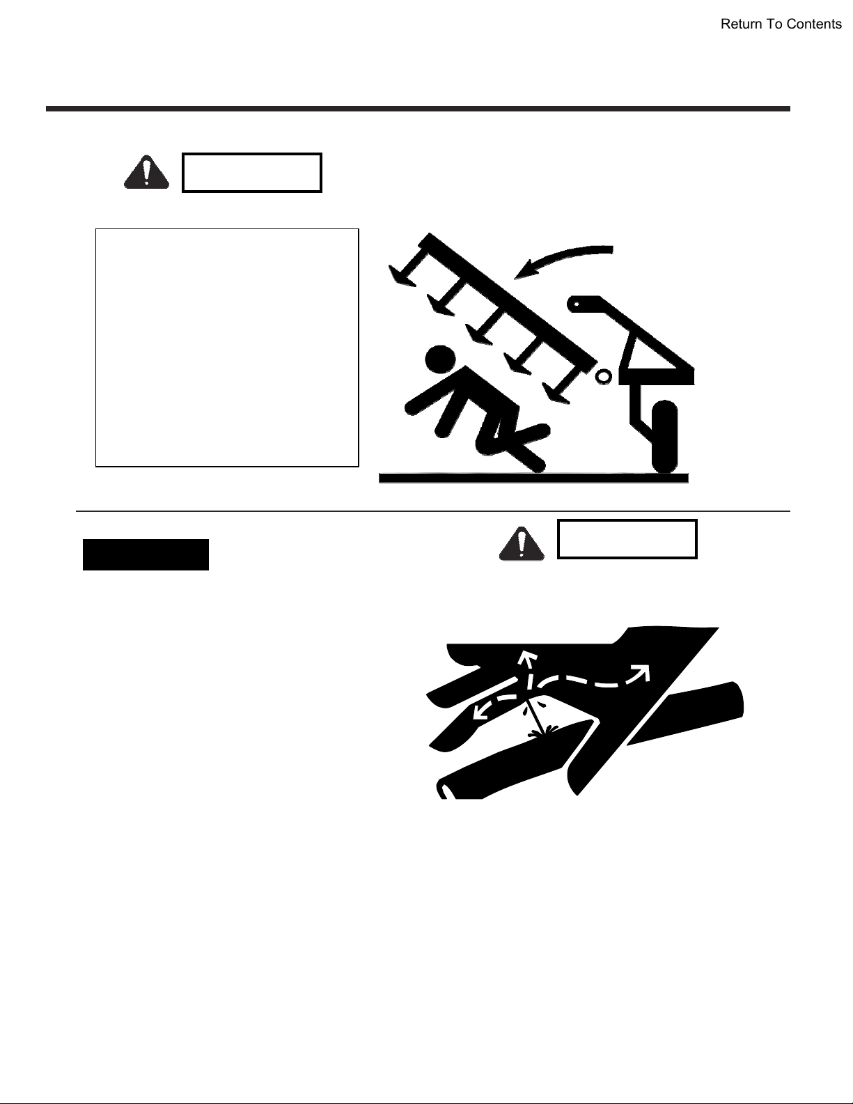
General Safety Precautions .........................................................................2
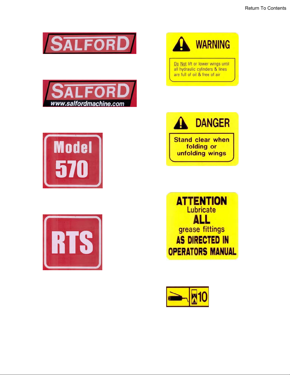
Safety Decal Locations............................................................................... 4
Frame Assembly ..........................................................................................6
Wing Fold Cylinder Installation.....................................................................8
Fifth Bar Installation.................................................................................. 10
Self leveling & Depth Control Installation ................................................... 12
Tongue installation ..................................................................................... 14
24ft, 27ft & 30ft Axle Layout ....................................................................... 16
41ft Axle Layout ........................................................................................ 17
8000lb Main Frame Axle Installation (24ft, 27ft, 30ft) ................................ 18
10000lb Main Frame Axle Installation (41ft)............................................... 20
8000lb Axle Assembly (24ft, 27ft, 30ft) ...................................................... 22
10000lb Axle Assembly (41ft) .................................................................... 24
5000lb Wing Frame Axle Installation (24ft – 41ft) ...................................... 26
5000lb Axle Assembly (24ft – 41ft) ........................................................... 28
5000lb Hub & Spindle Assembly ................................................................ 30
4000lb Hub & Spindle Assembly .............................................................. 32
8000lb Hub & Spindle Assembly............................................................... 34
Coulter Assembly
RTS Coulter & Mount Parts .......................................................................36
Coil-Tech Hub ............................................................................................ 38
Harrow Assembly
Harrow Setup ............................................................................................40
Tine Performance Settings ........................................................................41
62” Arm Assembly...................................................................................... 42
½” Tine Harrow Assembly .........................................................................44
14” Roller Assembly ..................................................................................46
Coulter & Harrow Layouts
13ft Coulter & Harrow Layout ....................................................................48
24ft Coulter & Harrow Layout ....................................................................50
27ft Coulter & Harrow Layout ....................................................................52
30ft Coulter & Harrow Layout ....................................................................54
41ft Coulter & Harrow Layout ....................................................................56
Hydraulics & Lights
Wing Fold Hydraulics ................................................................................. 58
Axle Lift Hydraulics....................................................................................60
Lights and Slow Moving Vehicle Sign ........................................................ 62
Transport Lock ........................................................................................... 65
Grease Bank .............................................................................................. 66

%RWKVLGHVRIWKHXEROW
PXVWEHWLJKWHQHGHTXDOO\
:$51,1*
'RQRWWLJKWHQRQHVLGHRIWKH
XEROWEHIRUHWKHRWKHUVLGH
6$/)25'5(&200(1'('72548(9$/8(6
127(67KHVHUHFRPPHQGHGWRUTXHYDOXHVDUHDSSOLFDEOHZKHQDSSOLHGWRWKHQXW
RQO\7KHVHUHFRPPHQGHGWRUTXHYDOXHVDUHDSSUR[LPDWHRQO\7KHWRUTXHWHQVLRQ
UHODWLRQVKLSLVDIIHFWHGE\OXEULFDWLRQVXUIDFHILQLVKWKUHDGILWSODWLQJORFNZDVKHUVHWF
'2127XVHWKHVHYDOXHVLIDGLIIHUHQWWRUTXHYDOXHRUWLJKWHQLQJSURFHGXUHLVJLYHQIRU
DVSHFLILFDSSOLFDWLRQ7RUTXHYDOXHVOLVWHGDUHIRUJHQHUDOXVHRQO\&KHFNWLJKWQHVVRI
IDVWHQHUVSHULRGLFDOO\
6KHDUEROWVDUHGHVLJQHGWRIDLOXQGHUSUHGHWHUPLQHGORDGV$OZD\VUHSODFHVKHDUEROWV
ZLWKLGHQWLFDOJUDGH
)DVWHQHUVVKRXOGEHUHSODFHGZLWKWKHVDPHRUKLJKHUJUDGH,IKLJKHUJUDGHIDVWHQHUV
DUHXVHGWKHVHVKRXOGRQO\EHWLJKWHQHGWRWKHVWUHQJWKRIWKHRULJLQDO
0DNHVXUHIDVWHQHUVWKUHDGVDUHFOHDQDQGWKDW\RXSURSHUO\VWDUWWKUHDGHQJDJHPHQW
7KLVZLOOSUHYHQWWKHPIURPIDLOLQJZKHQWLJKWHQLQJ
%2/76,=( *5$'( *5$'( *5$'(
IWOEV 1P IWOEV 1P IWOEV 1P
1&
1&
1&
1&
1&
570 RTS PARTS AND ASSEMBLY MANUAL
08-2007 Salford Farm Machinery Ltd. Page 1
Return To Contents

General Safety Precautions
Signal Words
The words DANGER, WARNING or CAUTION are
used with the safety alert symbol. Learn to
recognize the safety alerts, and follow the
recommended precautions and safe practices.
Three words are used in conjunction with the safety-alert symbol:
DANGER
WARNING
Indicates an imminently hazardous situation that, if not
avoided, will cause DEATH OR VERY SERIOUS INJURY.
Indicates a potentially hazardous situation that, if not
avoided, could cause DEATH OR SERIOUS INJURY.
CAUTION Indicates a potentially hazardous situation that, if not
avoided, may result in MINOR or MODERATE INJURY.
Replace any DANGER, WARNING, CAUTION or
instructional decal that is not readable or is missing.
The location and part number of these
decals is identified later in this section of the
manual.
The words Important and Note are not related to
personal safety but are used to give
additional information and tips for
operating or servicing this equipment.
IMPORTANT: Identifies special instructions or
procedures which, if not strictly
observed could result in damage to, or
destruction of the machine, process or
its surroundings.
NOTE: Indicates points of particular interest for more efficient and convenient repair or operation.
A CAREFUL OPERATOR IS THE BEST INSURANCE AGAINST AN ACCIDENT !
570 RTS PARTS AND ASSEMBLY MANUAL
Page 2 Salford Farm Machinery Ltd. 08-2007
Return To Contents

xWings may fall rapidly
causing injury.
xAlways stay clear of wings
when being lowered, raised
or in a elevated state.
xAlways use lockup device
provided when raised.
xEnsure cylinder is completely
filled with hydraulic fluid to
avoid unexpected
movement.
General Safety Precautions
•Do not search for high pressure hydraulic
leaks without hand and face protection. A
tiny, almost invisible leak can penetrate skin,
thereby requiring immediate medical
attention.
• Use cardboard or wood to detect leaks – never
your hands.
• Double check that all is clear before
operating hydraulics.
•Never remove hydraulic hoses or ends
with machine elevated. Relieve hydraulic
pressure before disconnecting hydraulic
hoses or ends.
• Maintain proper hydraulic fluid levels.
• Keep all connectors clean for positive connections.
• Ensure all fittings and hoses are in good condition.
• Do not stand under wings.
General O
H
y
draulics DANGER
DANGER
570 RTS PARTS AND ASSEMBLY MANUAL
08-2007 Salford Farm Machinery Ltd. Page 3
Return To Contents

SAFETY DECAL INSTALLATION
(1) “SALFORD” large – GD100
Place on frame tubes as shown
Quantity – 12
(2) “www.salfordmachine.com” GD102
Place on tongue
Quantity – 2
(3) “699” GD182
On tongue beside (2)
Quantity – 2
(4) “RTS” GD103
On tongue beside (2)&(3)
Quantity - 2
(5) “WARNING” GD110
Main front beam at corner
Quantity – 2
(6) “DANGER” GD111
All four corners of main frame
Quantity – 4
(7) “ATTENTION” GD112
On main frame beside serial number
Quantity – 1
(8) “Grease 10 hours” GD10810
Place near grease fittings in visible
spot. Quantity – 9
570 RTS PARTS AND ASSEMBLY MANUAL
08-2007 Salford Farm Machinery Ltd. Page 5
Return To Contents

SECURE FRAMES AT LEAST 39" ABOVE THE GROUND
CAUTION: OIL ON FRAMES IS VERY SLIPPERY, ESPECIALLY ON NEW PAINT.
CLEAN SPILLS IMMEDIATLY TO AVOID A PAINFUL FALL.
HINGE PIN INSTALLATION
MAKE SURE GREASE NIPPLE IS IN PLACE AND WILL ACCEPT GREASE.
1-SECURE FRAMES AT LEAST 39 inches OFF THE GROUND
2-ALIGN PIN HOLES, INSERT PIN #1 (1 1/2 X 7 1/2" WITH PLATE)
3- FASTEN WITH 5/8X1-1/2" BOLT AND LOCKWASHER.
ITEM NO. QTY PART NO. DESCRIPTION
1 4 GPSPEC24080 WING HINGE PIN (1 1/2 X 8")
2 4 BF10 5/8" LOCKWASHER
3 4 B1015 5/8 X 1-1/2" PLATED BOLT
4 4 GF1610 GREASE FITTING (1/ 8" NPT)
FRAME ASSEMBLY
570 RTS PARTS AND ASSEMBLY MANUAL
08-2007 Salford Farm Machinery Ltd. Page 7
Return To Contents

SYSTEM HAS BEEN PURGED OF AIR
FACE TOWARD THE BUTT.
ELBOW FITTING ON ROD END MUST
DO NOT PIN THE RODS UNTIL THE
1
3
4
5
4
2
PORTS OF CYLINDER FACE INWARD
ROD SIDE PORT
CAN NOT FACE UPWARD
OR IT WILL COLLIDE WITH
HINGE PLATE WHEN FOLDED
OUT OF SLOT
WASHERS OUTSIDE OF PLATE
TO KEEP PIN FROM SLIDING
FOLD CYLINDER INSTALLATION
570 RTS PARTS AND ASSEMBLY MANUAL
Page 8 Salford Farm Machinery Ltd. 08-2007
Return To Contents

FOLD CYLINDER INSTALLATION
Ports face in toward center of machine
!!!DO NOT PIN THE RODS UNTIL YOU HAVE PURGED AIR FROM THE FOLDING
SYSTEM. SEE THE HYDRAULIC SECTION FOR INSTRUCTION ON THIS.
WHEN TIME TO PIN THE RODS, DO NOT FORGET THE WASHERS. THE PINS CAN
SLIDE OUT OF THE SLOTTED HOLES OTHERWISE!!!
ITEM
NO. QTY. PART NO. DESCRIPTION
1 4 HS3524 3 1/2" BORE x 24" STROKE CYL.
1B 4 HS3536 (ON 41ft ONLY) 3 1/2" BORE X 36" STROKE CYL. (41ft)
2 4 GP16005A05 PIN 1" DIA. x 5" LG. - 2 HOLES
3 8 BF16S 1" SAE WASHER
4 12 BSC0515 5/16" x 1-1/2" COTTER PIN
5 4 GP1600314H04 PIN 1" DIA. x 3 1/4" LG. WITH HEAD
570 RTS PARTS AND ASSEMBLY MANUAL
08-2007 Salford Farm Machinery Ltd. Page 9
Return To Contents

19"
45 3/4"
24"
19"
45 3/4"
18"
18"
18"
18"
60"
150"
60" 24"
24ft
51"
46 3/4"
19"
19"
46 3/4"
51"
80"
18"
18"
150"
18"
80"
18"
27ft
19"
45 3/4"
65"
19"
46 3/4"
65"
100"
17"
18"
150"
17"
100"
18"
30ft
52"
39"
51 3/4"
51 3/4"
37"
37"
39"
52"
16"
16"
135"
182"
135"
16"
16"
40ft
570 RTS PARTS AND ASSEMBLY MANUAL
08-2007 Salford Farm Machinery Ltd. Page 11
Return To Contents

SELF LEVELING & DEPTH CONTROL
1. Bolt (#1) Self levelling mast onto the main frame with four 5/8 x 2-1/2" bolts.
2. Pin (#4) Pivot through (#1) mast with 1-1/2x15-1/4" pin. Fasten with two 1/2x3"
bolts and locknuts.
3. Pin rods of (#8) cylinders into (#4) with 1-1/4x10-1/4" Pin. Fasten with 5/16" cotter
pins. At this time you may hang (#21) the depth control rod on the cylinder rod pin
using the same cotter pin.
4. Face ports outward, pin cylinder butts with 1"x1-3/4" pins. Fasten with 1/4"cotter
pins.
5. The depth control rod (#21) should now be hanging off the cylinder rod pin. Slide
the adjustable stop (#20) onto the depth rod (#21). For now, leave it halfway
up the rod. DO NOT LEAVE THE ADJUSTABLE STOP (#20) MORE THAN HALF WAY
TOWARD THE MAST (#1). OTHERWISE, IT CAN BREAK WHEN THE MACHINE IS
RAISED.
6. Slide (#15) the valve bracket over (#21) the depth rod. Align the bracket straight
in front of the rod and fasten to the front beam with a ubolt (#16).
7. Bolt on (#17) the stroke control valve as shown with the inlet port down, and the
"poppet" up. Leave the plastic plugs in the valve for now to keep out dirt.
8. Pin (#13) the tripod brace as shown, with 2 bolts down and 1 up.
ITEM NO. QTY. PART NO. DESCRIPTION
1 1 C10575 550 SELF LEVELING MAST
1B 1 C10757 50' 570 SELF LEVELLING MAST
2 4 B1025 5/8 x 2 1/2" HEX BOLT GR 5
3 6 BN10L 5/8" NYLOCK NUT NC
4A 1 D70111 SELF-LEVELING PIVOT (24, 27, 30 & 41')
4B (50') 1 T00373 SELF LEVELING PIVOT (50' ONLY)
5 1 GP2401514A09 PIN 1 1/2" DIA. x 15 1/4" LG. - 2 HOLES
6 2 B0830 1/2" x 3" HEX BOLT
7 2 BN08L 1/2" NYLOCK NUT NC
8A 2 HSR35095 3 1/2" X 9 1/2" HYD. CYL. REPHASING (24, 27 & 30ft)
8B 2 HSR 40095 4" X 9 1/2" HYD. CYL. REPHASING (41ft ONLY)
8C 2 HSR4512 4-1/2" x 12" HYD. CYL, REPHASING (50ft ONLY)
9 1 GP20010A05 1 1/4" DIA. x 10 1/4" LG - 2 HOLE
10 6 BSC0520 5/16" x 2" COTTER PIN
11 2 GP1600314H04 PIN 1" DIA. x 3 1/4" LG. WITH HEAD
12 2 BSC0415 1/4" x 1 1/2" COTTER PIN
13 1 C10668 570 TRIPOD BRACE
14 2 GP16006A05 1"DIA. x 6 1/4" LG 2 HOLE PIN
15 1 D10011A POPET VALVE BRACKET
16 1 BU1046 U-BOLT 5/8" x 4" x 7 1/2" LG.
17 1 HPMSC10 STROKE CONTROL VALVE
18 2 B0525 5/16"NC x 2 1/2" HEX BOLT
19 2 BN05L 5/16" LOCK NUT
20 1 C1008 DETENT ADJUSTABLE STOP
21 1 C10667 DEPTH CONTROL ROD - 41"
22 2 GBB175150200 1 3/4" x 1 1/2" x 2" LG. HARD BUSHING
570 RTS PARTS AND ASSEMBLY MANUAL
08-2007 Salford Farm Machinery Ltd. Page 13
Return To Contents

1
2
3
7
8
9
10
11
12
4
5
6
20
22
21
17
18
19
13
14
15
23
16
TONGUE INSTALLATION
USE WASHERS AS
SHIMS TO TAKE UP
CLEARANCE BETWEEN
TONGUE AND CLEVIS
MOUNT MANUAL HOLDER
TO SIDE OF TRIPOD ARM
(AS SHOWN)
27
CHAIN RING AROUND
PIN #10
19A
25
26
24
19B
570 RTS PARTS AND ASSEMBLY MANUAL
Page 14 Salford Farm Machinery Ltd. 08-2007
Return To Contents

Right or Left hand? The
cylinder lug faces up
24, 27, 30FT. AXLE LAYOUT
WING AXLE
*HSR3208 CYLINDER
*5000LB PIVOT HUB
*4000LB WHEEL HUBS
*11L X 15SL TIRES
LOAD RANGE 'D'
MAIN AXLE
*HSR3508 CYLINDER
*8000LB PIVOT HUB
*5000LB WHEEL HUBS
*11L X 15FL TIRES
'HIGHWAY SERVICE'
LOAD RANGE 'F'
WING AXLE
*HSR3208 CYLINDER
*5000LB PIVOT HUB
*4000LB WHEEL HUBS
*11L X 15SL TIRES
LOAD RANGE 'D'
LH WING
In this book, all reference to RH or LH
assume the operator is behind the
machine (as shown here)
CENTER RH WING
FRONT
PIVOT
HUB
WHEEL
HUB
.
HUB TERMINOLOGY
IMPORTANT:
THREAD-LOCK ON
LUGNUTS
570 RTS PARTS AND ASSEMBLY MANUAL
Page 16 Salford Farm Machinery Ltd. 08-2007
Return To Contents
Table of contents
Other Salford Farm Equipment manuals