Viking Range vcwb300 User manual

INSTALLATION
INSTRUCTIONS
BUILT-IN FULL HEIGHT WINE CELLAR
(VCWB300 PROFESSIONAL MODEL)
Retain for Future Reference
VIKING RANGE CORPORATION
111 Front Street
Greenwood, Mississippi 38930 USA
(662) 455-1200
IMPORTANT - PLEASE READ AND FOLLOW
Make sure that incoming voltage is the same as unit rating. An electric rating plate specifying voltage, frequency, wattage,
amperage, and phase is attached to the product.
To reduce the risk of fire, electric shock, or injury to persons, installation work and electrical wiring must be done by qualified
people in accordance with all applicable codes and standards, including fire-rated construction.
The installer should leave these instructions with the consumer who should retain them for local inspector’s use and for
future reference.
GENERAL INFORMATION
It is your responsibility to :
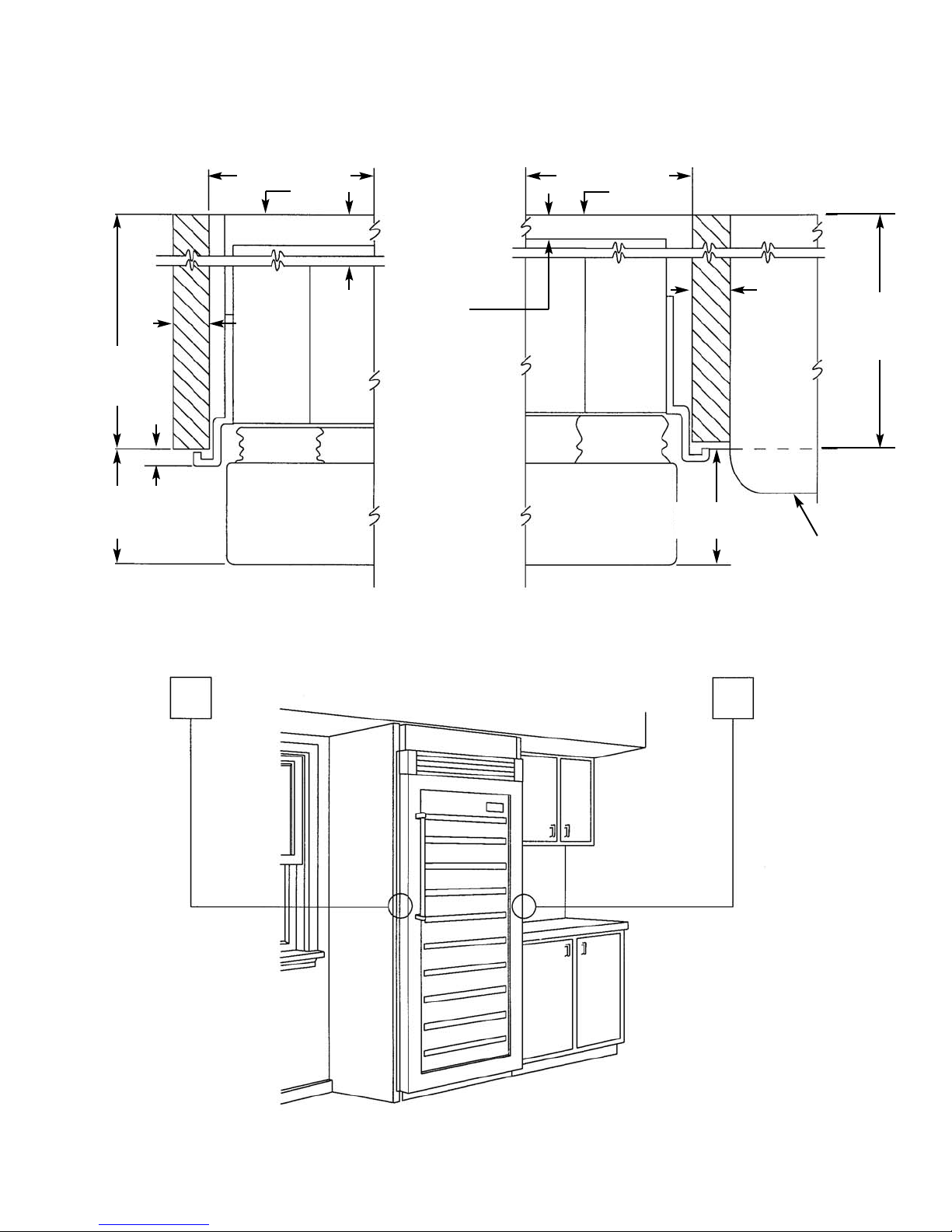
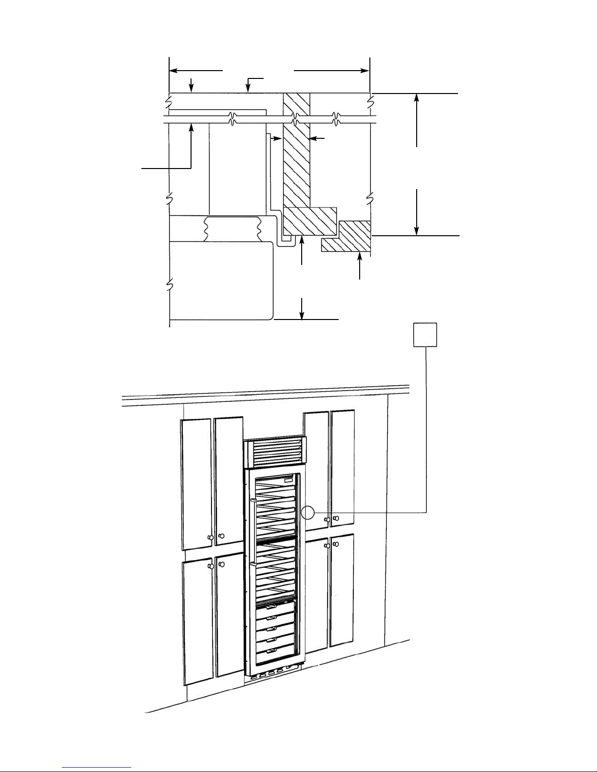
-comply with installation specifications and dimensions
-properly install wine cellar
-remove any moldings or decorative panels that prevent the wine cellar
from being serviced
-assure that floor will support wine cellar, door panels and contents
(approximately 1200 lbs. [540 kg]).
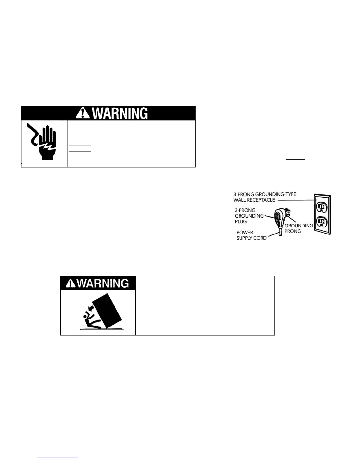
-provide a properly grounded electrical outlet
-assure that location will permit appliance doors to open 90ominimum
TTIIPPOOVVEERRHHAAZZAARRDD
WWiinneecceellllaarriissttoopphheeaavvyyaannddttiippsseeaassiillyy
wwhheennnnoottccoommpplleetteellyyiinnssttaalllleedd..
KKeeeeppddoooorrccl
loosseeddaannddsshheellvveessiinnppllaaccee
uunnttiillwwiinneecceellllaarriissccoommpplleetteellyyiinnssttaalllleedd
ppeerriinnssttaallllaattiioonniinnssttrruuccttiioonnss..
UUsseettwwoooorrmmoorreeppeeoopplleettoommoovveeaanndd
iinnssttaallllwwiinneecceellllaarr..
FFaaiilluurreettooddoossooccaannrreessuullttiinnddeeaatthhoorr
sseerriioou
ussiinnjjuurryy..
MMoossttoofftthheewwiinneecceellllaarr’’sswweeiigghhttiissaatttthhee
ttoopp..EExxttrraaccaarreeiissnneeeeddeeddwwhheennmmoovviinngg
tthheewwiinneecceellllaarrttoo
pprreevveennttttiippppiinngg..
UUsseeccaarrddbbooaarrddsshhiippppiinnggmmaatteerriiaalloorr
ppllyywwoooodduunnddeerrwwiinneecceellllaarruunnttiilliittiiss
iinnssttaalllleedd
iinntthheeooppeerraattiinnggppoossiittiioonnttoo
pprrootteeccttfflloooorrssuurrffaaccee..
YYoouurrssaaffeettyyaannddtthheessaaffeettyyooffootthheerrss
iissvveerryyiimmppoorrttaanntt..
We have provided many important safety
messages in this manual and on your
appliance. Always read and obey all
safety messages.
This is the safety alert symbol. This
symbol alerts you to hazards that
can kill or hurt you and others.
All safety messages will be
preceded by the safety alert symbol and
the word “DANGER” or “WARNING”.
These words mean:
YYoouuwwiillllbbeekkiilllleeddoorrsseerriioouussllyyiinnjjuurre
eddiiffyyoouu
ddoonn’’ttffoolllloowwiinnssttrruuccttiioonnss..
YYoouuccaannbbeekkiilllleeddoorrsseerriioouussllyyiinnjjuurreeddiiff
yyoouuddoonn’’ttffoolllloowwiinnssttr
ruuccttiioonnss..
All safety messages will identify the
hazard, tell you how to reduce the chance
of injury, and tell you what can happen if
the instructions are not followed.

2
BASIC SPECIFICATIONS AND DIMENSIONS
DDEESSCCRRIIPPTTIIOONNVVCCWWBB330000
Overall Width 30” (76.2 cm)
Overall Height from Bottom Min. 82 3/4” (210.2 cm) to Max. 84 1/16” (213.5 cm)
Overall Depth from Rear To rear edge of side trim 22 3/16” (56.4 cm)
To front of top grille 24 1/2” (62.2 cm)
To end of handle bracket 27” (68.6 cm)
Cutout Width 29 1/2” (74.9 cm)
Cutout Height 82 7/8” (210.5 cm) min.; 84 1/16” (213.5 cm) max.
Cutout Depth 24” (61.0 cm) min.
Electrical Requirements 115 volt, 60 Hz, 15 amp dedicated circuit; 3-wire cord with grounded
3-prong plug attached to product.
Maximum Amp Usage 2.0 amps
Overall Capacity 150 bottles
Approximate Shipping Weight 560 lbs. (252 kg)

3
1. TriTempTM storage system
2. Electronic control center
3. Convertible display shelves (2)
4. Extendable shelves (13)
5. Energy efficient and UV resistant glass doors
6. Low intensity lighting
7. Black interior
8. High temperature alarm (behind grille)
9. Door alarm (behind grille)
10. Connection to home security system (behind grille)
11. Door stop settings - 90o, 110o, 120o
12. Keyed door lock - (on front of door)
FEATURES OF YOUR WINE
CELLAR
1
12
2
3
4
5
6
7
89
10
11

4
SITE PREPARATIONS AND CONSIDERATIONS
PROFESSIONAL MODEL 30” W. FULL HEIGHT WINE CELLAR
CABINET OPENING DIMENSIONS
884411//1166((221133..55))ccmmmmaaxx..
aannttii--ttiippbbooaarrddaannddooppeenniinngghheeiigghhtt
882277//88mmiinn..((221100..55ccmm))
aannttii--ttiippbbooaarrddaannddooppeenniinngghheeiigghhtt

5
ELECTRICAL REQUIREMENTS
AREA REQUIREMENTS
IIttiisstthheeccuussttoommeerr’’ssrreessppoonnssiibbiilliittyyttoo::
•contact a qualified electrical installer.
•assure that the electrical installation is adequate and in conformance with the
National Electrical Code, ANSI/NFPA 70-latest edition or Canadian Electrical
Code C22.1-1998 and C22.2 No. 0-M91 (or latest edition), and all local
codes and ordinances. (115 volt, 60-Hz, 15 amp, fused, electrical supply is
required. It is required that a separate circuit serving only this appliance be
provided. This appliance is equipped with a power supply cord having a 3-
prong grounding plug. To minimize possible shock hazard, the cord must be
plugged into a mating 3-prong, grounding-type wall receptacle. Do not use
an extension cord.)
IIffccooddeessppeerrmmiittaasseeppaarraatteeggrroouunnddiinnggwwiirreettoobbee
uusseedd,,iittiissrreeccoommmmeennddeeddtthhaattaaqquuaalliiffiieeddeelleeccttrriicciiaan
n
ddeetteerrmmiinneetthhaatttthheeggrroouunnddiinnggppaatthhiissaaddeeqquuaattee..
DDooNNoottggrroouunnddttooaaggaassppiippee..CChheecckkwwiitthhaa
qquuaalliiffiieeddeelleeccttrriicciiaanniiffyyoouuaarreennoottssuurreetthhee
aapppplliiaanncceeiisspprrooppeer
rllyyggrroouunnddeedd..DDooNNootthhaavveeaa
ffuusseeiinntthheenneeuuttrraalloorrggrroouunnddiinnggcciirrccuuiitt..
EELLEECCTTRRIICCAALLSSHHOOCCKKHHAAZZAARRDD
PPlluuggiinnttooaaggrroouunnddeedd33--pprroonnggoouuttlleett..
DDOONNOOTTrreemmoovveeggrroouunnddpplluugg..
DDOONNOOTTuusseeaannaaddaapptteerr..
DDOONNOOTTuusseeaanneexxtteennssiioonnccoorrdd..
FFaaiilluurreettooffoolllloowwtthheesseeiinnssttrruuccttiioonnssccoouullddrreessuullttiinn
ffiirreeoorreelleeccttrriiccaallsshhoocckk.
.
VVeerriiffyytthheeffoolllloowwiinngg::
•Wine cellar can fit into residence and can be moved around corners and through doorways.
•Floors can support wine cellar’s weight plus wine weight (approximately 1200 pounds total).
•Remove anything attached to rear or side walls that can obstruct wine cellar installation.
•Cutout dimensions are accurate.
•Electrical outlet is in correct location.
Anti-Tip Requirements
The anti-tip boards should be fastened into position prior to moving the unit into the opening. Additional boards
may be required if wine cellar does not touch the back wall of the enclosure. To prevent wine cellar from tipping
forward, it must be secured in place with a solid soffit or wood block.
TTIIPPOOVVEERRHHAAZZAARRDD
WWiinneecceellllaarriissttoopphheeaavvyyaannddttiippsseeaassiillyywwhheennnnoott
ccoommpplleetteellyyiinnssttaalllleedd..
KKeeeeppddoooorrccl
loosseeddaannddsshheellvveessiinnppllaacceeuunnttiillwwiinneecceellllaarr
iissccoommpplleetteellyyiinnssttaalllleeddaannddsseeccuurreeddppeerriinnssttaallllaattiioonn
iinns
sttrruuccttiioonnss..UUsseettwwoooorrmmoorreeppeeoopplleettoommoovveeaanndd
iinnssttaallllwwiinneecceellllaarr..FFaaiilluurreettooddoossooccaannrreessuullttiinn
ddeeaatthh
oorrsseerriioouussiinnjjuurryy..

6
DOOR SWING AND TIPPING CONSIDERATIONS
2 1/2”
(6.4 cm)
90o
110o
120o
BBAACCKKWWAARRDD
TTIIPPPPIINNGGRRAADDIIUUSS
51 7/8”
(131.8 cm)
50 1/2”
(128.2 cm)
48 5/8”
(123.5 cm)
11 1/2”
(29.2 cm)
15 1/2”
(39.4 cm)
SSIIDDEE
TTIIPPPPIINNGGRRAADDIIUUSS
85 1/2
(217.1 cm)
106 1/2
(270.5 cm)
112 1/2
(285.7 cm)
87 1/2
(222.2 cm)

WINE CELLAR - OVERALL DIMENSIONS
7
82 7/8”
(210.5 cm)
min.
to
84 1/16”
(213.5 cm)

8
CABINET INFORMATION
Professional models fit “semi-flush” in standard 24” (61.0 cm) deep cabinet openings. The door face protrudes 2-5/16”
(5.9 cm) from the cabinet face. The handle protrudes an additional 2-1/2” (6.4 cm) into the room
29 1/2” (90.2 cm)
Wall
29 1/2” (90.2 cm)
Wall
24” (61.0 cm)
Standard
cabinet depth
3/4”
(1.9 cm)
Full end
panel
24” (61.0 cm)
Standard
cabinet
depth
3/4”
(1.9 cm)
Full end
panel
1 13/16”
(4.6 cm)
2 5/16”
(5.9 cm)
Offset
5/16”
(0.8 cm) DOOR DOOR
1 13/16” (4.6 cm)
space if 24”
(61.0 cm)
standard cabinet
depth used
2 5/16” (5.9 cm)
Offset
Countertop
Overhang
AA--AABB--BB
DDEETTAAIILLAA--AADDEETTAAIILLBB--BB

9
CABINET INFORMATION (continued)
CC--CC
DDEETTAAIILLCC--CC
29 1/2” (90.2 cm)
Wall
24” (61.0 cm)
Standard
cabinet
depth
3/4”
(1.9 cm)
Full end
panel
DOOR
1 13/16” (4.6 cm)
space if 24” (61.0 cm)
standard cabinet
depth used
2 5/16”
(5.9 cm)
Offset Partial Overlay
Cabinet Door

10
CUSTOM SIDE PANEL DIMENSIONS
For 3/4” (1.9 cm) Side Panels
OPTIONAL KICKPLATE NOTCH -
DIMENSIONS DETERMINED BY
CABINETS
OPTIONAL KICKPLATE
NOTCH - DIMENSIONS
DETERMINED BY CABINETS
882277//88””((221100..55ccmm))ttoo
884411//1166””((221133..55ccmm))
DDeeppeennddiinnggoonnhhooww
hhiigghhlleevveelliinnggffeeeettaarree
rraaiisseeddaannddccaabbiinneet
t
eenncclloossuurreehheeiigghhtt
222233//88””
((5566..99ccmm))
222233//1166””
((5566..44ccmm))
222233//1166””
((5566..44ccmm))
222233//88””
((5566..99ccmm))

11
CUSTOM WOOD FACINGS DIMENSIONS
Short Facing Dimensions (Top Two Zones)
Tall Facing Dimensions (Lower zone)
Each wine rack has a wood facing which can be removed. The facings can be stained, painted, or removed and
replaced with alternative wood facings. NOTE: A scrap sample should be tested in the unit before attaching
permanent changes to your wine cellar fronts. Some paints and/or stains can cause undesirable odors.
Remove the wood facing by removing the four 1/4” (.6 cm) hex head screws located on the inner edge of the wine
rack. Remove the wood facing. Follow the dimensions below to cut wood facing out of alternative woods.
SSCCAALLEE11..000000

12
WINE CELLAR INSTALLATION
UUsseettwwoooorrmmoorreeppeeoopplleettoommoovveeaannddiinnssttaallll
wwiinneecceellllaarr..FFaaiilluurreettooffoolllloowwtthhiissiinnssttrruuccttiioonn
ccaannrreessu
ullttiinnbbaacckkoorrootthheerriinnjjuurryy..TTooaavvooiidd
ppeerrssoonnaalliinnjjuurryy,,wweeaarrgglloovveesswwhheenn
ppeerrffoorrmmiinnggaannyyiinnssttaallllaattiioonn
pprroocceedduurreeaanndd
wweeaarreeyyeepprrootteeccttiioonnwwhheennccuuttttiinnggmmeettaall
ssttrraappss..
MMoossttoofftthheewwiinneecceellllaarr’’sswweeiigghhttiissaatttthheettoopp..EExxttrraaccaarreeiissnneeeeddeeddwwhheennmmoovviinnggtthheewwiinneecceellllaarrttoopprreevveennttttiippppiinngg..
DDooNNoottrreemmoovveepprrootteeccttiivveeffiillmmuunnttiillwwiinneecceellllaarriissiinnooppeerraattiinnggppoossiittiioonn..AAllllffoouurrlleevveelliinngglleeggssmmuussttccoonnttaacctttthheefflloooorrttoo
ssuuppppoorrttaannddssttaabbiilliizzeetthheeffuullllwweeiigghhtt..DDoonnoottddrrooppwwiinneecceellllaarr..
1. Remove exterior shipping materials prior to moving wine
cellar into home. Remove top and bottom strap
(see Figure 1).
2. Remove top cap (see Figure 1).
3. Cut carton rear approximately 1/4” (.64 cm) to 1” (2.5 cm)
from right corner (see figure 2) with a utility knife extended
1/4” (.6 cm). Remove carton and exterior packaging. Save
cardboard shipping material to protect floor surface when
installing wine cellar. Remove anti-tip
boards and kickplate from rear of wine
cellar (see Figure 3).
4. Remove shipping brackets from skid by
removing 4 bolts (2 each side) with a 1/2”
socket head driver (see Figure 4)
•Tilting wine cellar is not required to
remove shipping brackets.
5. Slip cart between wine cellar and skid.
Remove wine cellar from skid. Use excess
packaging to protect decorative trim. Verify
that leveling legs are
up (0” adjustment)
(see Figure 5).
6. To avoid floor damage,
use protective material.
(see Figure 6).
TTIIPPOOVVEERRHHAAZZAARRDD
WWiinneecceellllaarriissttoopphheeaavvyyaannddttiippsseeaassiillyy
wwhheennnnoottccoommpplleetteellyyiinnssttaalllleedd..KKeeeepp
ddoooorrc
clloosseeddaannddsshheellvveessiinnppllaacceeuunnttiill
wwiinneecceellllaarriissccoommpplleetteellyyiinnssttaalllleeddaanndd
sseeccuurreeddppeerriinnssttaallllaattiioonniin
nssttrruuccttiioonnss..
UUsseettwwoooorrmmoorreeppeeoopplleettoommoovveeaanndd
iinnssttaallllwwiinneecceellllaarr..FFaaiilluurreettooddoossooccaann
rreessuullttiinn
ddeeaatthhoorrsseerriioouussiinnjjuurryy..
Figure 1
Figure 2
Figure 3 Figure 4
Figure 5 Figure 6
KICKPLATE
ANTI-TIP BOARDS
BACK VIEW
BACK VIEW
(4) 1/2” (1.3 cm)
BOLTS
PROTECT TRIM FROM
STRAPPING
FRONT LEVELING
LEGS (2)
SKID
PROTECT
FLOOR

13
HOME SECURITY SYSTEM CONNECTION
NNOOTTEE::Contact a qualified electrician or authorized agent from alarm company to connect your home security system
to the wine cellar.
Home security system connection must be hooked up before the unit is installed.
1) Remove the four mounting screws attaching the unit compartment cover to the cabinet. (2 per side)
2) Remove the grille louver assembly to access the black safety grille.
3) Turn power off.
4) Remove the four screws that attach the top grille assembly to the mounting brackets.
5) Remove the 3 screws at the right side of the unit that attach the safety grille to the compartment cover.
6) Choose the desired switching position and connect according to alarm system requirements.
7) Replace the unit compartment cover.
The home security system will be activated if temperatures in the wine cellar fluctuate outside of the set point by 5ofor
and extended time period.
BBaacckkssiiddeeooffwwiinneecceellllaarr
RReedd,,wwhhiittee,,aannddbbllaacckk
wwiirriinngg**
**BBllaacckk==ccoommmmoonn
RReedd==nnoorrmmaallllyycclloosseedd
WWhhiittee==nnoorrmmaallllyyooppeenn

14
SECURING THE WINE CELLAR (3 OPTIONS)
OPTION 1
If a solid soffit is 1” (2.5 cm) or less above the wine cellar, anti-tip boards are not required. To secure the wine cellar
raise unit until compartment is firmly seated under the soffit.
OPTION 2
If a solid soffit is not available or soffit is more than 1” (2.5 cm) above wine cellar, center wood boards on rear wall 1/4”
(.6 cm) maximum above wine cellar. Attach wood boards to wall studs with six of the provided wood screws, making
sure that screws are engaged in wall studs 1 1/2” (3.8 cm) minimum and that boards extend 2” (5.0 cm) minimum over
the top rear of wine cellar compressor cover. To secure the wine cellar, raise unit until compartment is firmly seated
under the anti-tip board.
OPTION 3
Position the wood block over the unit and secure it to wall studs using eight of the provided wood screws and “L”
brackets. Make sure screws extend a minimum of 1” (2.5 cm) into each of the two wall studs. The wood block must
extend a minimum of 3” (7.6 cm) over the unit. To secure the wine cellar, raise unit until compartment is firmly seated
under the anti-tip boards.
EElleeccttrriiccaallSShhoocckkHHaazzaarrdd
DDiissccoonnnneeccttppoowweerraattbbrreeaakkeerroorrttuurrnnppoowweerrddiissccoonnnneeccttsswwiittcchh
ttooOOFFFFppoossiittiioonn
bbeeffoorreeppeerrffoorrmmiinnggaannyyiinnssttaallllaattiioonn
pprroocceedduurree..FFaaiilluurreettooddoossooccaannrreessuullttiinnddeeaatthhoorreelleeccttrriiccaall
ssh
hoocckk..
Solid Soffit
1”
(2.5 cm)
or less
1/4” (.6 cm)
maximum
Rear
wall
2” (5.0 cm)
minimum
OPTION 1 OPTION 2 OPTION 3
Two 2X4
boards
attached to
wall with six
wood screws
(minimum)
1/4” (.6 cm)
maximum
3” (7.6 cm)
minimum
“L” bracket
with (4) screws
on each end.
(1) 2X4
attached to
both “L”
brackets -
minimum of
1” (2.5 cm)
screws
Screws extend
minimum of
1” (2.5 cm)
into each wall
stud.

15
Before moving the wine cellar in place,
confirm the finished dimensions, electrical
location, minimum door and shelf clearances,
and door panel instructions. (See pages 3, 4,
& 5).
1. Position wine cellar in front of
cutout.
2. Verify operation by plugging
power cord in receptacle. PPoowweerr
sswwiittcchhwwiillllbbeesshhiippppeeddiinntthhee
““OONN””ppoossiittiioonnaannddsshhoowwrroooomm
sswwiittcchhwwiillllbbeeiinntthhee““OOFFFF””
ppoossi
ittiioonn..(If showroom switch is
switched to the “ON” position,
showroom mode is engaged and
power is shut-off to the
compressor. This mode is for
showroom display only).
Power “ON/OFF”
switch
Showroom
switch
3. Roll wine cellar into cutout to within 3” (7.6 cm) of being flush with cabinets. To avoid kitchen cabinet damage,
place cardboard between cabinets and wine cellar. Push cardboard back with wine cellar and remove cardboard
when wine cellar is in place.
4. Lift the wine cellar off the rollers, adjust to desired height and level wine cellar by using a 5/16” hex head wrench.
(Refer to Figure at the right)
a) To raise/lower right side rear, rotate the right side rear hex rod.
b) To raise/lower the left side rear, rotate the left
side rear hex rod.
c) To raise/lower the right side front, rotate the
right side front hex rod.
d) To raise/lower the left side front, rotate the left
side front hex rod.
NNOOTTEE: DO NOT use an electric driving device.
Overtightening can cause damage.
5. Align wine cellar with sides of cabinets by adjusting
leveling legs. Rotate leveling legs until firmly in
place against floor.
6. To secure wine cellar, raise unit until compartment
cover is firmly seated under the soffit or anti-tip boards.
7. Open door. Control panel should be lit. Verify the position of the power on/off and showroom switch if there is no
power to wine cellar.
VVIIEEWWSSHHOOWWNNWWIITTHHKKIICCKKPPLLAATTEERREEMMOOVVEEDD

16
KICKPLATE INSTALLATION
The kickplate consists of a two (2) part assembly: one top louvered panel and one bottom solid panel. Install the
kickplate with louvered section on the top. Flooring must allow the kickplate to be removed. See “Site Preparations”
for height clearance (page 3).
To install:
1. Insert the bottom (solid) panel into the open end of the top (louvered) panel. The holes in the bottom panel should
line up with the slots in the top panel.
2. Position the kickplate assembly along the front edge of the wine cellar.
3. Align the holes on both ends of the top (louvered ) panel with the holes in the base of the wine cellar.
4. Attach the kickplate to the wine cellar on each side with the two black phillips head screws provided.
5. Adjust the bottom (solid) panel to the desired height and fasten in place by tightening the screws in the slots.
There is approximately 1” (2.5 cm) of vertical adjustment on the kickplate.
AAttttaacchhttoouunniittwwiitthhtthheesseessccrreewwss
SSccrreewwssaannddsslloottss
ffoorraaddjjuussttmmeennttss
DOOR STOP ADJUSTMENT
1. Using a 3/16” allen wrench, remove door stop pin
located in bottom hinge.
2. The pin is factory set 110o. For 120oswing, move the
pin to the utmost forward stop hole. For 90oswing,
move the pin to the utmost rear stop hole.
HINGE ADJUSTMENT
1. Using a 3/16” allen wrench, remove the door stop
pin located in bottom hinge.
2. Using the height adjustment shim as a wrenching
device, rotate the height adjustment bushing
counterclockwise to raise or clockwise to lower the
location of the door.
3. When proper adjustment is reached, align shim with
door stop pin holes and replace door stop pin.
Firmly tighten pin in place.
120odoor stop
90odoor stop

17
WIRING DIAGRAM
BUILT-IN FULL HEIGHT WINE CELLAR

WIRING SCHEMATIC
BUILT-IN FULL HEIGHT WINE CELLAR
WARNING: ELECTRICAL GROUNDING INSTRUCTIONS
This appliance is equipped with a three prong grounding plug for your protection against shock hazard and should be
plugged directly into a properly grounded three prong receptacle. DO NOT CUT OR REMOVE THE GROUNDING
PRONG FROM THIS PLUG.
REFER ONLY TO FEATURES WHICH ARE EQUIPPED WITH THIS UNIT.
VIKING
111 Front Street • Greenwood, Mississippi 38930 USA • (662) 455-1200
Specifications subject to change without notice
F20155E (PS0305VR)
Table of contents
Other Viking Range Wine Cooler manuals
Popular Wine Cooler manuals by other brands

WMF
WMF Ambient Champagne & Wine Cooler instruction manual

Electrolux
Electrolux E24WC75HPS - Icon - Professional Series 48 Bottle Wine... Use and care guide

KitchenAid
KitchenAid KUWO24LSBX - Left Swing / Accepts Custom Panels ARCHITECT... Specification sheet

Dacor
Dacor EF24RBCSS use & care

Dacor
Dacor EF24LWCZ2SS installation instructions

Guzzanti
Guzzanti GZ-52 DD instruction manual

Avantgarde
Avantgarde LBWC-52SE2 instruction manual

WHISPER KOOL
WHISPER KOOL Platinum Split Version 4 Technician manual

Wine Master
Wine Master Hygromaster Installation and user guide

Magic Chef
Magic Chef MCWC50DSTF user manual

Cellar Cool
Cellar Cool CM 2500 owner's manual

N'Finity
N'Finity 273 02 50 instruction manual