Viking LSD-2 Instructions for use

• Adjustable disconnect time
• Routes both incoming and outgoing calls
• Allows an Emergency device to share a phone
line with other devices (fax machines, phones,
modems)
• Gives priority to the Emergency devices
• Incoming calls routed to one of two ports by
Caller ID, Distinctive Ring or Quick Call Back
• Status LED displays mode of operation
• Can store up to 12 Caller ID numbers
• Provides a busy signal to the phone port when
an Emergency device is in use
LSD-2
LSD-2
Line Sharing
Device
April 9, 2007
P
Pr
ra
ac
ct
ti
ic
ce
e
T
TE
EL
LE
EC
CO
OM
MS
SO
OL
LU
UT
TI
IO
ON
NS
SF
FO
OR
RT
TH
HE
E2
21
1S
ST
TC
CE
EN
NT
TU
UR
RY
Y
TECHNICAL
TECHNICAL
A Smart Line Sharing Device with
Inbound Switching Capability
Why pay for a dedicated line for your elevator/emergency
phone or alarm panel?
The LSD-2 Line Sharing Device allows the user to share an
existing phone line with an emergency phone or other prior-
ity alarm device. This can save hundreds of dollars a year
over leasing a dedicated phone line. The LSD-2 can be used
on any C.O. line or analog PABX/KSU station.
An outbound call on the DEVICE 2 (PRIORITY) port takes
priority over a call in progress on the DEVICE 1 port. Any
call in progress on the DEVICE 1 port will be disconnected
for 2 seconds, returning dial tone to the DEVICE 2 (PRIOR-
ITY) port. A busy signal is then sent to the DEVICE 1 port.
For incoming calls, the LSD-2 can route calls to the DEVICE 2 (PRIORITY) port using Caller ID,
Distinctive Ring, or Quick Call Back. All other calls will be routed to the DEVICE 1. Alternatively, the LSD-
2can be set up so that all inbound calls are routed to the DEVICE 2 (PRIORITY) port. Note: Caller ID
is not passed through the LSD-2 to the devices.
Important: When the emergency device is in use, the phone line is not available for normal use. Any additional
emergency calls will have to be made on another phone line. For this reason the LSD-2 is not recommended for
single line applications. Note: With some Central Office equipment, it may take up to 20 seconds to disconnect an
incoming call to the non-priority device. The emergency device must be capable of delaying this long before dialing.
F
Fe
ea
at
tu
ur
re
es
s
P
Ph
ho
on
ne
e.
..
..
.7
71
15
5.
.3
38
86
6.
.8
88
86
61
1
Power: 120VAC / 12VDC 500mA UL listed adapter provided
Dimensions: 133mm x 89mm x 44mm (5.25” x 3.5” x 1.75”)
Shipping Weight: .9 kg (2 lbs)
Environmental: 0° C to 32° C (32° F to 90° F) with 5% to 95%
non-condensing humidity
Talk Battery: 35V DC
Connections: 6 screw terminals
S
Sp
pe
ec
ci
if
fi
ic
ca
at
ti
io
on
ns
s
h
ht
tt
tp
p:
:/
//
/w
ww
ww
w.
.v
vi
ik
ki
in
ng
ge
el
le
ec
ct
tr
ro
on
ni
ic
cs
s.
.c
co
om
m
A
Ap
pp
pl
li
ic
ca
at
ti
io
on
ns
s
• Share an existing phone line with an emergency
device such as:
- Emergency phones
-Area of refuge phones
- Alarm panels
- ATM's
- Card readers
- Any device that needs instant access to a
phone line

I
In
ns
st
ta
al
ll
la
at
ti
io
on
n
VIKING©MODEL LSD-2
VIKING
ELECTRONICS
HUDSON, WI 54016
LINE SHARING DEVICE
SET
BUTTON
CALLER ID
CUSTOM RINGING
QUICK CALL BACK
C.O.
IN DEVICE 1 DEVICE 2
(PRIORITY)
STATUS
LED 1 2 3
POWER 12V DC
Push
To
Call
EMERGENCY
PHONE
MODEL E-1600A CALL
CONNECTED
-or-
12 3
4 5 6
7 8 9
0Send
C.O. Line
or Analog
PABX/KSU
Station
PABX/KSU
Trunk Port
Standard
Telephone
Emergency
Phone, Alarm
Panel or other
Priority Device
(E-1600A shown,
not included)
Step 1. Connect the incoming phone line or analog PABX station to the terminal positions marked CO IN.
Step 2. Connect the standard phones, unused trunk port or other non-priority device to the terminal positions marked DEVICE 1.
Step 3. Connect the Emergency Phone, Alarm Panel or other priority device to the terminal positions marked DEVICE 2
(PRIORITY).
Step 4. Connect the 12VDC wall adapter to the LSD-2.
Note: Be sure the LSD-2 has power available at all times. If power is lost, the phone line will be connected to the priority device only.
Fax
Machine
120V AC/
12V DC
Adapter
Included
Credit Card
Reader
IMPORTANT: Electronic
devices are susceptible to
lightning and power station
electrical surges from both the AC
outlet and the telephone line. It is
recommended that a surge protec-
tor be installed to protect against
such surges. Contact Panamax at
(800) 472-5555 or Electronic
Specialists Inc. at (800) 225-4876.
!
Modem
IF YOU HAVE A PROBLEM WITH A VIKING PRODUCT, PLEASE CONTACT: VIKING TECHNICAL SUPPORT AT (715) 386-8666
Our Technical Support Department is available for assistance weekdays between 8 a.m. and 5 p.m. central time. So that we can give you better service, before you call please:
1. Know the model number, the serial number and what software version you have (see serial label).
2. Have your Technical Practice in front of you.
3. It is best if you are on site.
RETURNING PRODUCT FOR REPAIR
The following procedure is for equipment that needs repair:
1. Customer must contact Viking's Technical Support Department at 715-386-8666 to obtain a Return Authorization (RA) number. The customer MUST have a complete description of the problem, with all
pertinent information regarding the defect, such as options set, conditions, symptoms, methods to duplicate problem, frequency of failure, etc.
2. Packing: Return equipment in original box or in proper packing so that damage will not occur while in transit. Static sensitive equipment such as a circuit board should be in an anti-static bag, sandwiched
between foam and individually boxed. All equipment should be wrapped to avoid packing material lodging in or sticking to the equipment. Include ALL parts of the equipment. C.O.D. or freight collect
shipments cannot be accepted. Ship cartons prepaid to: Viking Electronics, 1531 Industrial Street, Hudson, WI 54016
3. Return shipping address: Be sure to include your return shipping address inside the box. We cannot ship to a P.O. Box.
4. RA number on carton: In large printing, write the R.A. number on the outside of each carton being returned.
RETURNING PRODUCT FOR EXCHANGE
The following procedure is for equipment that has failed out-of-box (within 10 days of purchase):
1. Customer must contact Viking’s Technical Support at 715-386-8666 to determine possible causes for the problem. The customer MUST be able to step through recommended tests for diagnosis.
2. If the Technical Support Product Specialist determines that the equipment is defective based on the customer's input and troubleshooting, a Return Authorization (R.A.) number will be issued.
This number is valid for fourteen (14) calendar days from the date of issue.
3. After obtaining the R.A. number, return the approved equipment to your distributor, referencing the R.A. number. Your distributor will then replace the product over the counter at no charge. The
distributor will then return the product to Viking using the same R.A. number.
4. The distributor will NOT exchange this product without first obtaining the R.A. number from you. If you haven't followed the steps listed in 1, 2 and 3, be aware that you will have to pay a
restocking charge.
WARRANTY
Viking warrants its products to be free from defects in the workmanship or materials, under normal use and service, for a period of one year from the date of purchase from any authorized Viking dis-
tributor or 18 months from the date manufactured, which ever is greater. If at any time during the warranty period, the product is deemed defective or malfunctions, return the product to Viking
Electronics, Inc., 1531 Industrial Street, Hudson, WI., 54016. Customer must contact Viking's Technical Support Department at 715-386-8666 to obtain a Return Authorization (R.A.) number.
This warranty does not cover any damage to the product due to lightning, over voltage, under voltage, accident, misuse, abuse, negligence or any damage caused by use of the product by the pur-
chaser or others.
Vikings sole responsibility shall be to repair or replace (at Viking's option) the material within the terms stated above. VIKING SHALL NOT BE LIABLE FOR ANY LOSS OR DAMAGE OF ANY KIND
INCLUDING INCIDENTAL OR CONSEQUENTIAL DAMAGES RESULTING DIRECTLY OR INDIRECTLY FROM ANY BREACH OF ANY WARRANTY EXPRESSED OR IMPLIED, OR FOR ANY
OTHER FAILURE OF THIS PRODUCT. Some states do not allow the exclusion or limitation of incidental or consequential damages, so this limitation may not apply to you.
THIS WARRANTY IS IN LIEU OF ALL OTHER WARRANTIES, EXPRESSED OR IMPLIED, INCLUDING THE WARRANTIES OF MERCHANTABILITY AND FITNESS FOR A PARTICULAR PUR-
POSE, WHICH ARE HEREBY EXCLUDED BEYOND THE ONE YEAR DURATION OF THIS WARRANTY. Some states do not allow limitation on how long an implied warranty lasts, so the above
limitation may not apply to you.
W
Wa
ar
rr
ra
an
nt
ty
y

P
Pr
ro
og
gr
ra
am
mm
mi
in
ng
g
Switch
1
1
2
2
3
3
ON/OFF
ON
OFF
ON
OFF
ON
OFF
Description
Quick Call Back Mode
Disable Quick Call Back Mode
Distinctive Ring Mode
Disable Distinctive Ring Mode
Caller ID Mode
Disable Caller ID Mode
Note: When all switches are OFF, all inbound calls are
routed to the DEVICE 2 (PRIORITY) port.
VIKING©MODEL LSD-2
VIKING
ELECTRONICS
HUDSON, WI 54016
LINE SHARING DEVICE
SET
BUTTON
CALLER ID
CUSTOM RINGING
QUICK CALL BACK
STATUS
LED 1 2 3
POWER 12V DC
1 2 3
ON
S2
1 2 3
ON
OFF
S2
C.O.
IN DEVICE 1 DEVICE 2
(PRIORITY)
A. Call Back Mode
To place the LSD-2 in Call Back Mode, move DIP switch 1to the ON position.
B. Distinctive Ring Mode
To use the Distinctive Ring Mode, first purchase distinctive ringing service from your local phone service provider.
Then move DIP switch 2to the ON position. Note: In this mode the LSD-2 detects double or triple custom ringing.
C. Caller ID Mode
Step 1. Move DIP switch 3 to the ON position.
Step 2. Call into the LSD-2, if a Caller ID is received that is not stored in the unit, the LSD-2 Status LED will go into
a fast flash mode.
Step 3. While the LED is flashing fast, push the SET button. This will store the new Caller ID number into memory
and re-ring the DEVICE 2 (PRIORITY) port.
Note: If more than 12 numbers are attempted to be stored, the LSD-2 will re-ring the DEVICE 1 port. If
the Caller ID number is already stored in memory, the LED will not fast flash and the call will be automati-
cally routed to the DEVICE 2 (PRIORITY) port.
To clear out the Caller ID memory, press and hold the SET button while powering up the LSD-2. The
status LED will wink off showing that all 12 memory locations have been cleared.
If all of the switches are in the OFF position, all inbound calls are routed to the DEVICE 2 (PRIORITY) port. Once any of
the DIP switches are turned on, inbound calls default to the DEVICE 1 port unless the selected method is detected by the
LSD-2. The LSD-2 can use three different methods to determine if an incoming call is to be switched to the DEVICE 2 (PRI-
ORITY) port, instead of defaulting to the DEVICE 1 port. Each of these methods can be switched on or off using the DIP
switches located on the front edge of the board. When mixing modes of operation, the LSD-2 uses all the modes that are
turned on, and if any of the selected triggers are detected, the incoming call will be routed to the DEVICE 2 (PRIORITY)
port. If a selected trigger(s) is not detected, the inbound call will ring through to the DEVICE 1 port. For more information
on these modes, see Operation section C.
Note: To force all calls to be routed to the DEVICE 1 port, simply set DIP switch 3 to the ON position, but do not program
any caller ID numbers.
D. Disconnect Time
The length of time that the LSD-2 disconnects the DEVICE 1 port before gaining fresh dial tone for a DEVICE 2 (PRI-
ORITY) call, is factory set to 2 seconds. If this is not enough time for the line to return fresh dial tone, the LSD-2 can
be programmed to delay anywhere from 1 to 20 seconds.
Step 1. With the LSD-2 sitting in idle state, momentarily press the SET button and wait for the STATUS LED to blink the
current disconnect time in seconds. If the STATUS LED blinks twice, the disconnect time is set to 2 seconds.
Step 2. The STATUS LED remains off for approximately four seconds, during this time you may press the SET button once for
each second of disconnect time required (Example: five times for 5 seconds). The LSD-2 will confirm by blinking the
new disconnect time on the STATUS LED. If the LED flashes fast, the maximum setting has been exceeded.
Important: Be sure that the auto-dialing device on the DEVICE 2 (PRIORITY) port can be programmed to provide a
longer delay time than the LSD-2’s disconnect time. This assures that the auto-dialing device waits until there is fresh
dial tone before dialing.

Due to the dynamic nature of the product design, the information contained in this document is subject to change without notice. Viking Electronics, and its affiliates and/or
subsidiaries assume no responsibility for errors and omissions contained in this information. Revisions of this document or new editions of it may be issued to incorporate
such changes.
Fax Back Doc 262
ZF301680 Rev B
Printed in the U.S.A.
P
Pr
ro
od
du
uc
ct
tS
Su
up
pp
po
or
rt
tL
Li
in
ne
e.
..
..
.7
71
15
5.
.3
38
86
6.
.8
86
66
66
6F
Fa
ax
xB
Ba
ac
ck
kL
Li
in
ne
e.
..
..
.7
71
15
5.
.3
38
86
6.
.4
43
34
45
5
Caller ID switching relies on Caller ID services provided by your local telephone company. Any number pro-
grammed into one of the 12 Caller ID memory positions will be automatically routed to the DEVICE 2 (PRIORITY)
port (see Programming section C).
3. Caller ID Mode (switch 3 ON)
If a priority device, such as an emergency phone, is sharing a line with an “outbound only” device, such as a cred-
it card reader, or “outbound only” trunk, set all switches OFF and all inbound calls will be routed to the DEVICE 2
(PRIORITY) port.
4. All Inbound Calls Routed to the DEVICE 2 (PRIORITY) Port
If all inbound calls are to be routed to the DEVICE 1 port, set DIP switches 1& 2 OFF and 3to the ON position, but
do not program any caller ID numbers.
5. All Inbound Calls Routed to the DEVICE 1 Port
O
Op
pe
er
ra
at
ti
io
on
n
A. LED Status
B. Outbound Calls
When the LSD-2 is idle, the Status LED will be lit solid, and both ports are connected to an internally generated 35V
DC talk battery. If a device attached to the DEVICE 1 port goes off-hook, the phone line will be switched to the DEVICE
1port. If the device attached to the DEVICE 2 (PRIORITY) port goes off-hook, the phone line will be switched to the
DEVICE 2 (PRIORITY) port. If the device attached to the DEVICE 2 (PRIORITY) port goes off-hook while a call is in
progress on the DEVICE 1 port, both ports will be switched away from the phone line for two seconds (programmable
from 1-10 seconds), simulating a two second hang-up. The LSD-2 then reconnects the DEVICE 2 (PRIORITY) port to
the phone line. The device attached to the DEVICE 2 (PRIORITY) port receives fresh dial tone and is now able to dial
out. While the DEVICE 2 (PRIORITY) port is in use, a simulated busy tone is generated to any device attempting to
go off-hook on the DEVICE 1 port.
C. Inbound Calls
To use the Quick Call Back mode, call into the LSD-2 from another phone line, listen for a single ring back tone and
hang-up. Wait 6 seconds, then call back to the LSD-2 (within 20 seconds). The LSD-2 will route the incoming call
to the DEVICE 2 (PRIORITY) port instead of defaulting to the DEVICE 1 port (see Programming section A).
1. Quick Call Back Mode (switch 1 ON)
Custom Ring switching relies on “Distinctive” or “Custom Ring” services provided by your local telephone compa-
ny. Any call with a custom ring cadence will be routed to the DEVICE 2 (PRIORITY) port. Inbound calls with stan-
dard ring cadence will be routed to the DEVICE 1 port. The LSD-2 accepts both double and triple custom ring
cadences as custom (see Programming section B).
2. Custom Ring Mode (switch 2 ON)
LED Status
Lit up
Flash
Flash After Ring
Fast Flash
Operation
Power is applied to the LSD-2.
The LSD-2 is active.
In the Quick Call Back mode, the LED will continue to flash for 20 seconds.
In the Caller ID mode, the LED will fast flash if a Caller ID number is received that is not in memory.
Other Viking Accessories manuals
Viking
Viking SR-1 Instructions for use
Viking
Viking LS-911 Instructions for use
Viking
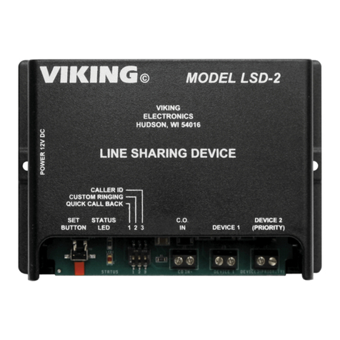
Viking LSD-2 User manual
Viking
Viking E16W User manual
Viking
Viking DB40 Instructions for use

Viking
Viking FRDI1240D User manual

Viking
Viking EP16W User manual
Viking
Viking DDBB536RSS Technical manual
Viking
Viking SO-24A Instructions for use
Viking
Viking ERAM-4M Instructions for use
Viking
Viking DDWB301CRSS User manual
Viking
Viking FWCI1150GR User manual
Viking
Viking BLK-4 User manual
Viking
Viking PB-1 Instructions for use

Viking
Viking SR-1 User manual
Viking
Viking Designer DFUW1441CR User manual

Viking
Viking W24W User manual

Viking
Viking SO-24A Instructions for use

Viking
Viking LS-911 User manual

Viking
Viking DDWB301CRSS User manual


