Viking VFR-500 User manual

VFR-500
Conventional Releasing Panel
Program Templates
Manual #5403799–REV A
9/23


3
VFR-500 PROGRAM TEMPLATES • 5403799 • REV A • 9/23
Programming
VFR-500 Standard Program Information
The VFR-500 has 30 standard program templates which are detailed on the following pages. Selecting one of these programs will
automatically program every function of the panel except custom zone and banner messages.
NOTE:
The release soak time defaults to continuous for all programs.
In the Agent suppression programs, the predischarge timer for detectors defaults to 60 seconds. The predischarge timer for manual
stations defaults to 30 seconds. The abort mode defaults to UL.
Default programming allows the activation of a zone programmed as, Manual Release, to override any cross zoning and abort to
activate the release output it is mapped to. Abort override can be changed in the panel programming by allowing manual release
zones to be aborted.
Default programming does not allow zones programmed as Manual Release to be aborted. This can be changed in the panel
programming.
VFR-500 Standard Program Information
Press ENT to enter program mode.
Scroll down to see the various menu options. A blinking arrow indicates the current option.
Users can also simply enter the option number. See the Menu Tree for a complete list and location of options
Follow the on-screen instructions
NOTE: Some options have YES/NO selections. Use the up/down arrows to change selection.
To enter one of the standard programs:
1. Press ENT
2. Enter 6 or scroll down to PROGRAMMING, indicated by a ashing and press ENT.
3. Enter the password. Factory default password is, 1111.
4. Press 1 OR ENT to select PRORGAM NUMBER.
5. Enter the desired program number
6. Press ENT
7. Press 1 to accept the new program
8. Press ENT to accept the change and update the panel
All zones and outputs are now programmed and all mapping of zones to correlating outputs is complete.
For abort functionality (available in Agent Release Mode only), pre-discharge or soak timers are required, repeat steps 1-3. Then
select the desired option and follow the on-screen instructions.
Modications to standard programs can be easily accomplished using the Viking programming tool.
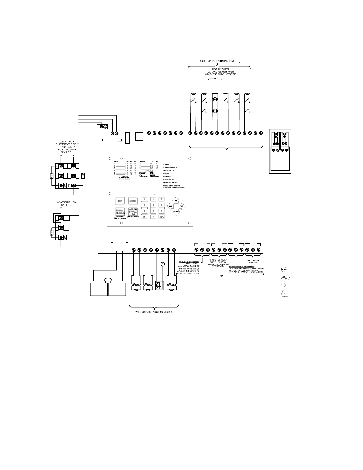
The following is an explanation of how the various programs operate and information about the types of devices that are to be
connected to the input (Initiating) zones and output (NAC) circuits.
If none of the standard programs are acceptable for the operation required, selecting program 0 allows the user to create a
custom program. Standard programs can also me modied to create custom programs. Simply select the standard program that is
closest to the operation needed. Then selecting program 0 allows the user to make changes to the previously selected program as
necessary.
If zone characteristics need to be modied, including latching, output paterns, manual/auto silence behiavior. Repeat steps 1-6
above and select program 0. After the panel restarts to edit zone characteristics repeat steps 1-3 and select 6 ZONES.
The water based extinguishing programs are numbered 1-19 and 30-35. The agent extinguishing programs are numbered 20-24.

4
VFR-500 PROGRAM TEMPLATES • 5403799 • REV A • 9/23
To enable Class A on zones 3 or 4:
1. Install IDC-6 with address 16 as described on pg. 3-23
2. Press ENT
3. Enter 8 or scroll down to PANEL SETUP, indicated by a ashing and press ENT
4. Enter the password. Factory default is 1111.
5. Enter 2 or scroll down to LEARN MENU, indicated by a ashing and press ENT
6. Press 1 OR ENT to select LEARN ALL
The panel will search for connected devices
7. Press 1 or ENT to select P-LINK FOUND to review devices
Addr 16 (IDC-6)
8. Press ESC to exit learn all menu
9. Press 1 to Accept the new devices
10. Press ENT to accept the change and update the panel
11. Press ENT
12. Enter 8 or scroll down to PANEL SETUP, indicated by a ashing and press ENT
13. Enter the password. Factory default is 1111.
14. Enter 7 or scroll down to IDC6 F/CA ZONE 3, indicated by a ashing and press ENT
15. Press any key to accept
16. Press ESC to exit PANEL SETUP menu
17. Press 1 to Accept
18. Press ENT to accept the change and update the panel
Repeat steps 11 – 18 using 8 or scroll down to IDC6 F/CA ZONE 4 to enable class A for zone 4. Zone 3 class A wiring to INPUT
3 / INPUT 4 on IDC-6 address 16 as shown on page 3-24. Zone 4 class A wiring to INPUT 5 / INPUT 6 on IDC-6 address 16.
When using standard program templets IDC-6 address 16 INPUTS 1 and INPUT 2 are unused.

5
VFR-500 PROGRAM TEMPLATES • 5403799 • REV A • 9/23
Menu Tree
Main Menu
1=View History 2=Enable/
Disable
3=Set Date/
Time
4=Walk Test
5=System Tools
1=Ethernet Tools
2=Erase History
3=Lamp Test
4=Main Revision
6=Programming
1=Program Number
2=Predischarge
Timer
3=Manual Predschg
Timer
4=Soak Time
5=Abort Type
6=Zone Attributes
7=Circuit Attributes
8= Zone Mapping
9=Cross Zones
7=Data Transfer
1=Remote Access
2=Email History
3=Email Cong
4=Email Test
5=Server Status
8=Panel Setup
1=System Setup
2=Learn Menu
3=Panel Default
4=IP Settings
5=Dt ID Pswd
6=Prog ID Pswd
7=Use IDC-6 for
CA on Zone 3
8=Use IDC-6 for
CA on Zone 4
9=QRS Fill
1=System Setup
1=Panel Name
2=Idle Message
3=Display Options
4=Clock Options
5=Strobe-Silence
6=Buzzer On during
Alarm
7=24Hr Resound
8=User Codes
9=More…
9=More…
1=AC Report Delay
2=Water Flow Delay
3=Door Holder Delay
4=Email Setup
5= Enable Agent
Release
6=Time Zone
7=DST Setup
8=Job Details
9=PLink Devices
9=PLink Devices
1=Edit Device
2=Add New Device
3=Delete Device

6
VFR-500 PROGRAM TEMPLATES • 5403799 • REV A • 9/23
OUTPUT
1
BATT
2
OUTPUT OUTPUT
34
OUTPUT
RED
BLACK
NC
NC NO
NO COM
COM
-
-
+
+
+-+-+-
LIMITED AND
NON-POWER
SUPERVISED
-+-+
ZONE 1
-+ +-
ZONE 2
TROUBLE ALARM
CA2Z WILL CONVERT
ZONES 5 AND 6 CLASS B
ZONES INTO CLASS A ZONES
OPTIONAL CLASS A
CONNECTIONS EOLR IS
NOT USED FOR CLASS A
OPTIONAL
CA2Z CLASS
A MODULE
BATTERY CABLE
OBSERVE POLARITY
RED +
BLACK -
+
POS
-
NEG
+
POS
-
NEG
12V BATT. 12V BATT.
+
ZONE 7
ZONE 6ZONE 5ZONE 4
NL
LINE
NEUTRAL
EARTH GROUND
FROM DEDICATED UNSWITCHED
CIRCUIT IN SERVICE PANEL
120VAC-240VAC 50/60 HZ
USE 14AWG OR HEAVIER GAUGE
WIRE WITH 600V INSULATION
- -+-+--+-+
ZONE 1
+-SA B
PLINK
+ -
PANEL INPUTS (INITIATING ZONES)
CONNECT TO NORMALLY OPEN DEVICES
OR COMPATIBLE 2 WIRE SMOKE
DETECTORS.
MAXIMUM LINE RESISTANCE: 100 OHMS
(EXCEPT WITH LINEAR HEAT DETECTION)
OPTIONAL CA2Z MOUNTING LOCATION
ZONE 5 AND 6 ONLY
AC IN CONNECTOR
NON-POWER
LIMITED AND
SUPERVISED
+
AUX OUT
+-
ZONE 2ZONE 3
FUSE -
4A-250VAC
TIME LAG P-COMM
21 21
SUPV WTRFL
RELEASE NC
NC NO
NO COM
COM
DRY CONTACTS RATED AT 3A, 30VDC
RELAY CONTACTS
ASSY
DIODE
EOL
BLACK
RED
5.1K
EOLR
BLACK
RED
EOLR
5.1K
BLACK
RED
RELEASE
ALARM
GENERAL
SOLENOID
SUPERVISORY
BELL
WATERFLOW
EOLR
5.1K
BLACK
RED
RELEASE
STATION
WATER
FLOW
SWITCH
DETECTION
CONVENTIONAL
EOLR
5.1K
VALVE
TAMPER
SUPERVISORY
LOWA
IR
PRESSURE
SUPERVISORY
SWITCH
09472
09470
EOLR
5.1K
EOLR
5.1K
EOLR
5.1K
EOLR
5.1K
MANUAL
EOLR
5.1K
S
Initiating device
Notication appliance
Solenoid
End-of-Line diode assy
Legend
Wiring Diagram Programs
NOTES:
1. Run eld wiring and ensure connections are proper by metering wires. Resistance reading should be 5.1K ohms with end-oine
resistor (EOLR) at last device. The end-of-line resistor are supplied with the panel Install EOLR on all unused circuits.
2. Connect one circuit at a time and apply AC power.
3. Connect batteries to the panel
4. Press ENT to enter PROGRAM mode
5. Press 6 or scroll down to #6 and press ENT, (The selection is indicated by a ashing arrow next to the number.
6. Enter the password. (Factory default is 1111)
7. Press 1 or press ENT. (1 should be the highlighted selection)
8. The display shows the current program number. Press 1 to change to program 1. Press ENT.
9. Press 1 to accept the change.
10. Press ENT to accept the change
PROGRAM #1

7
VFR-500 PROGRAM TEMPLATES • 5403799 • REV A • 9/23
PROGRAM #1
For One Sprinkler System
Viking Sprinkler
System Types
2 Release
Zones,
Waterow
Zone, &
Manual Release
Zone
1. Single Interlocked Preaction System with Electric Release
2. Deluge System with Electric Release
3. Non-Interlocked Preaction System with Electric Release
4. Double Interlocked Preaction System with Electric/Pneumatic Release
OUTPUTS
(Indicating Circuits)
ZONES (Initiating Circuits)
#1 #2 #3 #4 #5 #6 #7
Low Air
Supervisory
Zone
Valve Tamper
Supervisory
Zone
Conventional
Detection
Zone
Conventional
Detection
Zone
Waterow
Zone
Manual
Release
Zone
Unused
#1 General Alarm X X X X
#2 Waterow X
#3 Release Solenoid X X X
#4 Supervisory Bell X X
OPERATION DESCRIPTION
Inputs: 2 Conventional Detection zones, 1 Waterow zone, 1 Manual Release zone, 2 Supervisory zones
Outputs: 1 General Alarm, 1 Waterow Alarm, 1 Solenoid Release, 1 Supervisory Bell
Operation: Activation of Conventional Detection zone #3 or #4 or Manual Release zone #6 will activate output #3
(Release Solenoid) and output #1 (General Alarm)
Activation of Waterow zone #5 will activate output #2 (Waterow) and output #1 (General Alarm)
Activation of Low Air Supervisory zone #1 or Valve Tamper Supervisory zone #2 will operate output #4
(Supervisory Bell).
NOTES:
1. Connect EOL Diode assembly IN SERIES as shown with Solenoid on output #3 (Release Solenoid). Black wire to negative
terminal on panel and Red wire through Solenoid to positive terminal on panel.
2. Polarity is shown on indicating circuits in an activated (in alarm) condition.
3. Install EOLR (provided) on all unnused circuits.
4. See the instruction manual for circuit information, panel limits, and battery sizing.
5. For wire routing instructions through the releasing panel, see Fig 1 on page 2-7 of the instruction manual.
6. See instruction manual for proper programming.
7. See instruction manual for list of compatible smoke detectors.
8. See specic system type data page for proper pressure switch settings.

8
VFR-500 PROGRAM TEMPLATES • 5403799 • REV A • 9/23
OUTPUT
1
BATT
2
OUTPUT OUTPUT
34
OUTPUT
RED
BLACK
NC
NC NO
NO COM
COM
-
-
+
+
+-+-+-
LIMITED AND
NON-POWER
SUPERVISED
-+-+
ZONE 1
-+ +-
ZONE 2
TROUBLE ALARM
CA2Z WILL CONVERT
ZONES 5 AND 6 CLASS B
ZONES INTO CLASS A ZONES
OPTIONAL CLASS A
CONNECTIONS EOLR IS
NOT USED FOR CLASS A
OPTIONAL
CA2Z CLASS
A MODULE
BATTERY CABLE
OBSERVE POLARITY
RED +
BLACK -
+
POS
-
NEG
+
POS
-
NEG
12V BATT. 12V BATT.
+
ZONE 7
ZONE 6ZONE 5ZONE 4
NL
LINE
NEUTRAL
EARTH GROUND
FROM DEDICATED UNSWITCHED
CIRCUIT IN SERVICE PANEL
120VAC-240VAC 50/60 HZ
USE 14AWG OR HEAVIER GAUGE
WIRE WITH 600V INSULATION
- -+-+--+-+
ZONE 1
+-SA B
PLINK
+ -
PANEL INPUTS (INITIATING ZONES)
CONNECT TO NORMALLY OPEN DEVICES
OR COMPATIBLE 2 WIRE SMOKE
DETECTORS.
MAXIMUM LINE RESISTANCE: 100 OHMS
(EXCEPT WITH LINEAR HEAT DETECTION)
OPTIONAL CA2Z MOUNTING LOCATION
ZONE 5 AND 6 ONLY
AC IN CONNECTOR
NON-POWER
LIMITED AND
SUPERVISED
+
AUX OUT
+-
ZONE 2ZONE 3
FUSE -
4A-250VAC
TIME LAG P-COMM
21 21
SUPV WTRFL
RELEASE NC
NC NO
NO COM
COM
DRY CONTACTS RATED AT 3A, 30VDC
RELAY CONTACTS
ASSY
DIODE
EOL
BLACK
RED
5.1K
EOLR
BLACK
RED
RELEASE
ALARM
GENERAL
SOLENOID
BLACK
RED
5.1K
EOLR EOLR
5.1K
EOLR
5.1K
EOLR
5.1K
WATER
FLOW
SWITCH
DETECTION
CONVENTIONAL
VALVE
TAMPER
SUPERVISORY
SYSTEMS
1&2
LOWAIR
PRESSURE
SUPERVISORY
SWITCH
SYSTEMS
1&2
09472
09470
WATER
FLOW
SWITCH
09470
SYSTEM 1SYSTEM2
BLACK
RED
ASSY
DIODE
EOL
WATERFLOW
SYSTEMS
RELEASE
SOLENOID
SYSTEMS12
5.1K 5.1K
EOLREOLR
PROGRAM #2
NOTES:
1. Run eld wiring and ensure connections are proper by metering wires. Resistance reading should be 5.1K ohms with end-oine
resistor (EOLR) at last device. The end-of-line resistor are supplied with the panel Install EOLR on all unused circuits.
2. Connect one circuit at a time and apply AC power.
3. Connect batteries to the panel
4. Press ENT to enter PROGRAM mode
5. Press 6 or scroll down to #6 and press ENT, (The selection is indicated by a ashing arrow next to the number.
6. Enter the password. (Factory default is 1111)
7. Press 1 or press ENT. (1 should be the highlighted selection)
8. The display shows the current program number. Press 2 to change to program 2. Press ENT.
9. Press 1 to accept the change.
10. Press ENT to accept the change
S
N.O. Initiating Device
Conventional Detection
Notication Appliance
Solenoid
End-of-Line Diode Assy
Legend

9
VFR-500 PROGRAM TEMPLATES • 5403799 • REV A • 9/23
PROGRAM #2
For Two Sprinkler Systems Operating Independantly From Each Other
Viking Sprinkler
System Types
2 Split Release
Zones and 2
Waterow Zones
1. Single Interlocked Preaction System with Electric Release
2. Deluge System with Electric Release
3. Non-Interlocked Preaction System with Electric Release
4. Double Interlocked Preaction System with Electric/Pneumatic Release
OUTPUTS
(Indicating Circuits)
ZONES (Initiating Circuits)
#1 #2 #3 #4 #5 #6 #7
Valve Tamper
Supervisory
Zone for Systems
1 & 2
Low Air
Supervisory
Zone for
Systems 1 & 2
Conventional
Detection
Zone for
System 1
Conventional
Detection
Zone for
System 2
Waterow
Zone for
System 1
Waterow
Zone for
System 2
Unused
#1 General Alarm X X X X
#2 Release Solenoid #1 X
#3 Release Solenoid #2 X
#4 Waterow X X
OPERATION DESCRIPTION
Inputs: 2 Conventional Detection zones, 2 Waterow zones, 2 Supervisory zones
Outputs: 1 General Alarm, 1 Waterow Alarm, 2 Solenoid Release
Operation: Activation of Conventional Detection zone #3 will activate output #2 (Release Solenoid #1) and output
#1 (General Alarm)
Activation of Conventional Detection zone #4 will activate output #3 (Release Solenoid #2) and output
#1 (General Alarm)
Activation of Waterow zone #5 or #6 will activate output #1 (General Alarm) and output #4
(Waterow)
Activation of Valve Tamper Supervisory zone #1 or Low Air Supervisory zone #2 will operate
supervisory trouble relay.
NOTES:
1. Connect EOL Diode assembly IN SERIES as shown with Solenoid on output #2 (Release Solenoid) and output #3 (Release
Solenoid). Black wire to negative terminal on panel and Red wire through Solenoid to positive terminal on panel.
2. Polarity is shown on indicating circuits in an activated (in alarm) condition.
3. Install EOLR (provided) on all unnused circuits.
4. See the instruction manual for circuit information, panel limits, and battery sizing.
5. For wire routing instructions through the releasing panel, see Fig 1 on page 2-7 of the instruction manual.
6. See instruction manual for proper programming.
7. See instruction manual for list of compatible smoke detectors.
8. See specic system type data page for proper pressure switch settings.

10
VFR-500 PROGRAM TEMPLATES • 5403799 • REV A • 9/23
OUTPUT
1
BATT
2
OUTPUT OUTPUT
34
OUTPUT
RED
BLACK
NC
NC NO
NO COM
COM
-
-
+
+
+-+-+-
LIMITED AND
NON-POWER
SUPERVISED
-+-+
ZONE 1
-+ +-
ZONE 2
TROUBLE ALARM
CA2Z WILL CONVERT
ZONES 5 AND 6 CLASS B
ZONES INTO CLASS A ZONES
OPTIONAL CLASS A
CONNECTIONS EOLR IS
NOT USED FOR CLASS A
OPTIONAL
CA2Z CLASS
A MODULE
BATTERY CABLE
OBSERVE POLARITY
RED +
BLACK -
+
POS
-
NEG
+
POS
-
NEG
12V BATT. 12V BATT.
+
ZONE 7
ZONE 6ZONE 5ZONE 4
NL
LINE
NEUTRAL
EARTH GROUND
FROM DEDICATED UNSWITCHED
CIRCUIT IN SERVICE PANEL
120VAC-240VAC 50/60 HZ
USE 14AWG OR HEAVIER GAUGE
WIRE WITH 600V INSULATION
- -+-+--+-+
ZONE 1
+-SA B
PLINK
+ -
PANEL INPUTS (INITIATING ZONES)
CONNECT TO NORMALLY OPEN DEVICES
OR COMPATIBLE 2 WIRE SMOKE
DETECTORS.
MAXIMUM LINE RESISTANCE: 100 OHMS
(EXCEPT WITH LINEAR HEAT DETECTION)
OPTIONAL CA2Z MOUNTING LOCATION
ZONE 5 AND 6 ONLY
AC IN CONNECTOR
NON-POWER
LIMITED AND
SUPERVISED
+
AUX OUT
+-
ZONE 2ZONE 3
FUSE -
4A-250VAC
TIME LAG P-COMM
SUPV WTRFL
RELEASE NC
NC NO
NO COM
COM
DRY CONTACTS RATED AT 3A, 30VDC
RELAY CONTACTS
ASSY
DIODE
EOL
BLACK
RED
5.1K
EOLR
BLACK
RED
EOLR
5.1K
BLACK
RED
RELEASE
ALARM
GENERAL
SOLENOID
SUPERVISORY
BELL
WATERFLOW
EOLR
5.1K
BLACK
RED
RELEASE
STATION
WATER
FLOW
SWITCH
DETECTION
CONVENTIONAL
EOLR
5.1K
VALVE
TAMPER
SUPERVISORY
LOWA
IR
PRESSURE
SUPERVISORY
SWITCH
0947
09470
EOLR
5.1K
EOLR
5.1K
EOLR
5.1K
EOLR
5.1K
MANUAL
EOLR
5.1K
3
LOWA
IR
PRESSURE
SWITCH
0947
3
ALARM
21
2
2
1
1
S
Initiating device
Notication appliance
Solenoid
End-of-Line diode assy
Legend
NOTES:
1. Run eld wiring and ensure connections are proper by metering wires. Resistance reading should be 5.1K ohms with end-oine
resistor (EOLR) at last device. The end-of-line resistor are supplied with the panel Install EOLR on all unused circuits.
2. Connect one circuit at a time and apply AC power.
3. Connect batteries to the panel
4. Press ENT to enter PROGRAM mode
5. Press 6 or scroll down to #6 and press ENT, (The selection is indicated by a ashing arrow next to the number.
6. Enter the password. (Factory default is 1111)
7. Press 1 or press ENT. (1 should be the highlighted selection)
8. The display shows the current program number. Press 3 to change to program 3. Press ENT.
9. Press 1 to accept the change.
10. Press ENT to accept the change
PROGRAM #3

11
VFR-500 PROGRAM TEMPLATES • 5403799 • REV A • 9/23
PROGRAM #3
For One Sprinkler System
Viking Sprinkler
System Types
2 Cross
Release zones,
Waterow
zone, and
Manual
Release zone
1. Double Interlocked Preaction System with Electric/Pneu-Lectric Release
OUTPUTS
(Indicating Circuits)
ZONES (Initiating Circuits) Software
Zone
#1 #2 #3 #4 #5 #6 #7 #8
Low Air
Supervisory
Zone
Valve Tamper
Supervisory
Zone
Conventional
Detection
Zone
Low Air
Alarm
Zone
Waterow
Zone
Manual
Release
Zone
Unused Release
Type
Zone
#1 General Alarm X X X X
#2 Waterow X
#3 Release Solenoid X X X X X XX*
#4 Supervisory Bell X X X
OPERATION DESCRIPTION
Inputs: 1 Conventional Detection zone cross zoned with 1 Low Air Alarm zone, 1 Waterow zone, 1 Manual
Release zone, 2 Supervisory zones
Outputs: 1 General Alarm, 1 Waterow, 1 Release Solenoid, 1 Supervisory Bell
Operation: Simultaneous activation of both the Conventional Detection zone #3 and the Low Air Alarm zone #4 will
activate output #3 (Release solenoid), output #1 (General alarm), and output #4 (Supervisory Bell)
Activation of Conventional Detection zone #3 will activate output #1 (General Alarm)
Activation of Low Air Alarm zone #4 will activate output #4 (Supervisory Bell)
Activation of Waterow zone #5 will activate output #2 (Waterow) and output #1 (General Alarm)
Activation of Manual Release zone #6 will activate output #3 (Release Solenoid) and output #1 (General
Alarm)
Activation of Low Air Supervisory zone #1 or Valve Tamper Supervisory zone #2 will operate output #4
(Supervisory Bell)
NOTES:
1. Connect EOL Diode assembly IN SERIES as shown with Solenoid on output #3 (Release Solenoid). Black wire to negative
terminal on panel and Red wire through Solenoid to positive terminal on panel.
2. Polarity is shown on indicating circuits in an activated (in alarm) condition.
3. Install EOLR (provided) on all unnused circuits.
4. See the instruction manual for circuit information, panel limits, and battery sizing.
5. For wire routing instructions through the releasing panel, see Fig 1 on page 2-7 of the instruction manual.
6. See instruction manual for proper programming.
7. See instruction manual for list of compatible smoke detectors.
8. See specic system type data page for proper pressure switch settings.
* Release Outputs which are Cross-Zoned need a Software Zone in order to work properly. The Software Zone Number will be displayed
upon a release.
XX = Cross-Zoned

12
VFR-500 PROGRAM TEMPLATES • 5403799 • REV A • 9/23
PROGRAM #4
NOTES:
1. Run eld wiring and ensure connections are proper by metering wires. Resistance reading should be 5.1K ohms with end-oine
resistor (EOLR) at last device. The end-of-line resistor are supplied with the panel Install EOLR on all unused circuits.
2. Connect one circuit at a time and apply AC power.
3. Connect batteries to the panel
4. Press ENT to enter PROGRAM mode
5. Press 6 or scroll down to #6 and press ENT, (The selection is indicated by a ashing arrow next to the number.
6. Enter the password. (Factory default is 1111)
7. Press 1 or press ENT. (1 should be the highlighted selection)
8. The display shows the current program number. Press 4 to change to program 4. Press ENT.
9. Press 1 to accept the change.
10. Press ENT to accept the change
S
N.O. Initiating Device
Conventional Detection
Notication Appliance
Solenoid
End-of-Line Diode Assy
Legend
OUTPUT
1
BATT
2
OUTPUT OUTPUT
34
OUTPUT
RED
BLACK
NC
NC NO
NO COM
COM
-
-
+
+
+-+-+-
LIMITED AND
NON-POWER
SUPERVISED
-+-+
ZONE 1
-+ +-
ZONE 2
TROUBLE ALARM
CA2Z WILL CONVERT
ZONES 5 AND 6 CLASS B
ZONES INTO CLASS A ZONES
OPTIONAL CLASS A
CONNECTIONS EOLR IS
NOT USED FOR CLASS A
OPTIONAL
CA2Z CLASS
A MODULE
BATTERY CABLE
OBSERVE POLARITY
RED +
BLACK -
+
POS
-
NEG
+
POS
-
NEG
12V BATT. 12V BATT.
+
ZONE 7
ZONE 6ZONE 5ZONE 4
NL
LINE
NEUTRAL
EARTH GROUND
FROM DEDICATED UNSWITCHED
CIRCUIT IN SERVICE PANEL
120VAC-240VAC 50/60 HZ
USE 14AWG OR HEAVIER GAUGE
WIRE WITH 600V INSULATION
- -+-+--+-+
ZONE 1
+-SA B
PLINK
+ -
PANEL INPUTS (INITIATING ZONES)
CONNECT TO NORMALLY OPEN DEVICES
OR COMPAT IBLE 2 WIRE SMOKE
DETECTORS.
MAXIMUM LINE RESISTANCE: 100 OHMS
(EXCEPT WITH LINEAR HEAT DETECTION)
OPTIONAL CA2Z MOUNTING LOCATION
ZONE 5 AND 6 ONLY
AC IN CONNECTOR
NON-POWER
LIMITED AND
SUPERVISED
+
AUX OUT
+-
ZONE 2ZONE 3
FUSE -
4A-250VAC
TIME LAG P-COMM
21 21
SUPV WTRFL
RELEASE NC
NC NO
NO COM
COM
DRY CONTACTS RATED AT 3A, 30VDC
RELAY CONTACTS
ASSY
DIODE
EOL
BLACK
RED
5.1K
EOLR
BLACK
RED
RELEASE
ALARM
GENERAL
SOLENOID
BLACK
RED
EOLR
5.1K
EOLREOLREOLR
5.1K
EOLR
5.1K
WATER
FLOW
SWITCH
VALVE
TAMPER
SUPERVISORY
SYSTEMS
1&2
LOWAIR
PRESSURE
SUPERVISORY
SWITCH
SYSTEMS
1&2
09472
09470
DETECTION
CONVENTIONAL
BLACK
RED
WATERFLOW
SYSTEMS
RELEASE
SOLENOID
SYSTEMS12
RELEASE
STATION
MANUAL
EOLR
5.1K
5.1K 5.1K
ASSY
DIODE
EOL5.1K
EOLR

13
VFR-500 PROGRAM TEMPLATES • 5403799 • REV A • 9/23
NOTES:
1. Connect EOL Diode assembly IN SERIES as shown with Solenoid on output #2 (Release Solenoid) and output #3 (Release
Solenoid). Black wire to negative terminal on panel and Red wire through Solenoid to positive terminal on panel.
2. Polarity is shown on indicating circuits in an activated (in alarm) condition.
3. Install EOLR (provided) on all unnused circuits.
4. See the instruction manual for circuit information, panel limits, and battery sizing.
5. For wire routing instructions through the releasing panel, see Fig 1 on page 2-7 of the instruction manual.
6. See instruction manual for proper programming.
7. See instruction manual for list of compatible smoke detectors.
8. See specic system type data page for proper pressure switch settings.
PROGRAM #4
For Two Sprinkler Systems - Operating Simultaneously
Viking Sprinkler
System Types
2 Dual Release
Zones,
Waterow
Zone, and Dual
Manual Release
Zone
1. Single Interlocked Preaction System with Electric Release
2. Deluge System with Electric Release
3. Non-Interlocked Preaction System with Electric Release
4. Double Interlocked Preaction System with Electric/Pneumatic Release
OUTPUTS
(Indicating Circuits)
ZONES (Initiating Circuits)
#1 #2 #3 #4 #5 #6 #7
Valve Tamper
Supervisory
Zone for
Systems 1 & 2
Low Air
Supervisory
Zone for
Systems 1 & 2
Conventional
Detection
Zone for
System 1
Conventional
Detection
Zone for
System 2
Waterow
Zone
Manual
Release
Zone
Unused
#1 General Alarm X X X X
#2 Release Solenoid #1 X X X
#3 Release Solenoid #2 X X X
#4 Waterow X
OPERATION DESCRIPTION
Inputs: 2 Conventional Detection zones, 1 Waterow zone, 1 Manual Release zone, 2 Supervisory zones
Outputs: 1 General Alarm, 1 Waterow, 2 Release Solenoids
Operation: Activation of Conventional Detection zone #3 or #4 or Manual Release zone #6 will activate output #2
(Release Solenoid #1) and output #3 (Release Solenoid #2) and output #1 (General Alarm)
Activation of Waterow zone #5 will activate output #4 (Waterow) and output #1 (General Alarm)
Activation of Valve Tamper Supervisory zone #1 or Low Air Supervisory zone #2 will operate
supervisory trouble relay

14
VFR-500 PROGRAM TEMPLATES • 5403799 • REV A • 9/23
PROGRAM #5
S
N.O. Initiating Device
Conventional Detection
Notication Appliance
Solenoid
End-of-Line Diode Assy
Legend
NOTES:
1. Run eld wiring and ensure connections are proper by metering wires. Resistance reading should be 5.1K ohms with end-oine
resistor (EOLR) at last device. The end-of-line resistor are supplied with the panel Install EOLR on all unused circuits.
2. Connect one circuit at a time and apply AC power.
3. Connect batteries to the panel
4. Press ENT to enter PROGRAM mode
5. Press 6 or scroll down to #6 and press ENT, (The selection is indicated by a ashing arrow next to the number.
6. Enter the password. (Factory default is 1111)
7. Press 1 or press ENT. (1 should be the highlighted selection)
8. The display shows the current program number. Press 5 to change to program 5. Press ENT.
9. Press 1 to accept the change.
10. Press ENT to accept the change
OUTPUT
1
BATT
2
OUTPUTOUTPUT
34
OUTPUT
RED
BLACK
NC
NC NO
NO COM
COM
-
-
+
+
+-+-+-
LIMITED AND
NON-POWER
SUPERVISED
-+-+
ZONE 1
-+ +-
ZONE 2
TROUBLE ALARM
CA2Z WILL CONVERT
ZONES 5 AND 6 CLASS B
ZONES INTO CLASS A ZONES
OPTIONAL CLASS A
CONNECTIONS EOLR IS
NOT USED FOR CLASS A
OPTIONAL
CA2Z CLASS
A MODULE
BATTERY CABLE
OBSERVE POLARITY
RED +
BLACK -
+
POS
-
NEG
+
POS
-
NEG
12V BATT. 12V BATT.
+
ZONE 7
ZONE 6ZONE 5ZONE 4
NL
LINE
NEUTRAL
EARTH GROUND
FROM DEDICATED UNSWITCHED
CIRCUIT IN SERVICE PANEL
120VAC-240VAC 50/60 HZ
USE 14AWG OR HEAVIER GAUGE
WIRE WITH 600V INSULATION
- -+-+--+-+
ZONE 1
+-SA B
PLINK
+ -
PANEL INPUTS (INITIATING ZONES)
CONNECT TO NORMALLY OPEN DEVICES
OR COMPAT IBLE 2 WIRE SMOKE
DETECTORS.
MAXIMUM LINE RESISTANCE: 100 OHMS
(EXCEPT WITH LINEAR HEAT DETECTION)
OPTIONAL CA2Z MOUNTING LOCATION
ZONE 5 AND 6 ONLY
AC IN CONNECTOR
NON-POWER
LIMITED AND
SUPERVISED
+
AUX OUT
+-
ZONE 2ZONE 3
FUSE -
4A-250VAC
TIME LAG P-COMM
SUPV WTRFL
RELEASE NC
NC NO
NO COM
COM
DRY CONTACTS RATED AT 3A, 30VDC
RELAY CONTACTS
ASSY
DIODE
EOL
BLACK
RED
5.1K
EOLR
BLACK
RED
RELEASE
ALARM
GENERAL
SOLENOID
BLACK
RED
EOLR
5.1K
EOLREOLREOLR
5.1K
EOLR
WATER
FLOW
SWITCH
DETECTION
CONVENTIONAL
VALVE
TAMPER
SUPERVISORY
LOWAIR
PRESSURE
SUPERVISORY
SWITCH
0947
09470
TE
RLO
RELEASE
STATION
MANUAL
EOLR
5.1K
5.1K 5.1K
3
SWITCH
0947
3
LOWAIR
PRESSURE
AR
M
A
L
5.1K
5.1K
EOLR
SUPERVISORY
BELL BELL
UB
2
2
1
1
21
5.1K
EOLR
BLACK
RED

15
VFR-500 PROGRAM TEMPLATES • 5403799 • REV A • 9/23
NOTES:
1. Connect EOL Diode assembly IN SERIES as shown with Solenoid on output #2 (Release Solenoid) and output #3 (Release
Solenoid). Black wire to negative terminal on panel and Red wire through Solenoid to positive terminal on panel.
2. Polarity is shown on indicating circuits in an activated (in alarm) condition.
3. Install EOLR (provided) on all unnused circuits.
4. See the instruction manual for circuit information, panel limits, and battery sizing.
5. For wire routing instructions through the releasing panel, see Fig 1 on page 2-7 of the instruction manual.
6. See instruction manual for proper programming.
7. See instruction manual for list of compatible smoke detectors.
8. See specic system type data page for proper pressure switch settings.
PROGRAM #5
For One Sprinkler System- NYC Special
Viking Sprinkler
System Types
Release Zone
and Manual
Release Zone
1. Single Interlocked Preaction System with Electric Release
2. Deluge System with Electric Release
3. Non-Interlocked Preaction with Electric Release
4. Double Interlocked Preaction System with Electric/Pneumatic Release
OUTPUTS
(Indicating Circuits)
ZONES (Initiating Circuits)
#1 #2 #3 #4 #5 #6 #7
Valve Tamper
Supervisory
Zone
Low Air
Supervisory
Zone
Conventional
Detection
Zone
Low Air
Alarm
Zone
Waterow
Zone
Manual
Release
Zone
Unused
#1 General Alarm X X X
#2 Supervisory Bell X X X
#3 Release Solenoid X X
#4 Trouble Bell
OPERATION DESCRIPTION
Inputs: 1 Conventional Detection zone, 1 Waterow zone, 1 Low Air Alarm zone, 1 Manual Release zone, 2
Supervisory zones
Outputs: 1 General Alarm, 1 Trouble Bell, 1 Release Solenoid, 1 Supervisory Bell
Operation: Activation of Conventional Detection zone #4 or Manual Release zone #6 will activate output #3
(Release Solenoid) and output #1 (General Alarm)
Activation of Waterow zone #5 will activate output #1 (General Alarm)
Activation of Low Air Alarm zone #2 or Low Air Supervisory zone or Valve Tamper Supervisory zone
#1will activate output #2 (Supervisory Bell)
A trouble condition, (low battery, wire short in outputs, loss AC, panel problem) will activate output #4
(Trouble Bell) and trouble relay

16
VFR-500 PROGRAM TEMPLATES • 5403799 • REV A • 9/23
PROGRAM #6
S
N.O. Initiating Device
Firecycle Detector
Notication Appliance
Solenoid
End-of-Line Diode Assy
Legend
NOTES:
1. Run eld wiring and ensure connections are proper by metering wires. Resistance reading should be 5.1K ohms with end-oine
resistor (EOLR) at last device. The end-of-line resistor are supplied with the panel Install EOLR on all unused circuits.
2. Connect one circuit at a time and apply AC power.
3. Connect batteries to the panel
4. Press ENT to enter PROGRAM mode
5. Press 6 or scroll down to #6 and press ENT, (The selection is indicated by a ashing arrow next to the number.
6. Enter the password. (Factory default is 1111)
7. Press 1 or press ENT. (1 should be the highlighted selection)
8. The display shows the current program number. Press 6 to change to program 6. Press ENT.
9. Press 1 to accept the change.
10. Press ENT to accept the changer
OUTPUT
1
BATT 2
OUTPUT OUTPUT
34
OUTPUT
RED
BLACK
NC
NC NO
NO COM
COM
-
-
+
+
+-+-+-
LIMITED AND
NON-POWER
SUPERVISED TROUBLE ALARM
BATTERY CABLE
OBSERVE POLARITY
RED +
BLACK -
+
POS
-
NEG
+
POS
-
NEG
12V BATT. 12V BATT.
+
ZONE 7
ZONE 6ZONE 5ZONE 4
NL
LINE
NEUTRAL
EARTH GROUND
FROM DEDICATED UNSWITCHED
CIRCUIT IN SERVICE PANEL
120VAC-240VAC 50/60 HZ
USE 14AWG OR HEAVIER GAUGE
WIRE WITH 600V INSULATION
- -+-+--
+-
+
ZONE 1
+-SA B
PLINK
+ -
PANEL INPUTS (INITIATING ZONES)
CONNECT TO NORMALLY OPEN DEVICES
OR COMPATIBLE 2 WIRE SMOKE
DETECTORS.
MAXIMUM LINE RESISTANCE: 100 OHMS
(EXCEPT WITH LINEAR HEAT DETECTION)
OPTIONAL CA2Z MOUNTING LOCATION
ZONE 5 AND 6 ONLY
AC IN CONNECTOR
NON-POWER
LIMITED AND
SUPERVISED
+
AUX OUT
+-
ZONE 2ZONE 3
FUSE -
4A-250VAC
TIME LAG P-COMM
SUPV WTRFL
RELEASE NC
NC NO
NO COM
COM
DRY CONTACTS RATED AT 3A, 30VDC
RELAY CONTACTS
ASSY
DIODE
EOL
BLACK
RED
5.1K
EOLR
BLACK
RED
RELEASE
ALARM
GENERAL
SOLENOID
5.1K
EOLR
SUPERVISORY
BELL SOLENOID
/
ON
ASSY
DIODE
EOL
BLACK
RED
BLACK
RED
1
2
21
2
1
RELEASE
STATION
WATER
FLOW
SWITCH
DETECTORS
FIRECYCLE
VALVE
TAMPER
SUPERVISORY
LOW AIR
PRESSURE
SUPERVISORY
SWITCH
09473
LOWAIR
PRESSURE
ALARM
SWITCH
09473 09470
EOLR
5.1K
EOLR
5.1K
EOLR
5.1K
EOLR
5.1K
EOLR
5.1K
MANUAL
EOLR
5.1K

17
VFR-500 PROGRAM TEMPLATES • 5403799 • REV A • 9/23
NOTES:
1. Connect EOL Diode assembly IN SERIES as shown with Solenoid on output #3 (Release Solenoid) and output #4 (N/O
Solenoid). Black wire to negative terminal on panel and Red wire through Solenoid to positive terminal on panel.
2. Polarity is shown on indicating circuits in an activated (in alarm) condition.
3. Install EOLR (provided) on all unnused circuits.
4. See the instruction manual for circuit information, panel limits, and battery sizing.
5. For wire routing instructions through the releasing panel, see Fig 1 on page 2-7 of the instruction manual.
6. See instruction manual for proper programming.
7. See specic system type data page for proper pressure switch settings.
8. Connect EOL resistor after last FIRECYCLE detector on return line to common terminal in FIRECYCLE Detector zone #1.
9. Set the soak timer to desired duration period. Factory setting is continuous. Recommend 60 seconds minimum.
10. Loss of DC power below 20 volt causes output #3 (Release Solenoid) and output #4 (N/O Solenoid) to drop out.
11. Use only Viking FIRECYCLE detectors on FIRECYCLE Detector zone #1.
12. Refer to Viking technical data sheet F_051304 for Firecycle single interlock multi-cycle operation.
13. For UL864 Approved Programming Options, see page 6-102.
PROGRAM #6
For One Sprinkler System
Viking Sprinkler
System Types
Release Zone
and Manual
Release Zone
1. FIRECYCLE III Single Interlocked Preaction Multicycle System
2. FIRECYCLE III Single Interlocked Preaction Multicycle System - NYC Special
OUTPUTS
(Indicating Circuits)
ZONES (Initiating Circuits)
#1 #2 #3 # #5 #6 #7
Low Air
Supervisory
Zone
Valve Tamper
Supervisory
Zone
FIRECYCLE
Detector Zone
Low Air
Alarm Zone
Waterow
Zone
Manual
Release Zone
Unused
#1 General Alarm X X X
#2 Supervisory Bell X X X
#3 Release Solenoid X X
#4 N/O Solenoid X X X
OPERATION DESCRIPTION
Inputs: FIRECYCLE Detector zone, Low Air Alarm zone, 1 Waterow zone,1 Manual Release zone, 2
Supervisory zones
Outputs: 1 General Alarm, 1 Supervisory Alarm, 1 Release Solenoid, and 1 N/O Solenoid
Operation: Activation of FIRECYCLE Detector zone #3 will activate output #1 (General Alarm), output #3
(Release Solenoid), and output #4 (N/O Solenoid)
Activation of Low Air Alarm zone #4 will activate output #2 (Supervisory Bell) and output #4 (N/O
Solenoid)
Activation of Waterow zone #5 will activate output #1 (General Alarm) and output #4 (N/O
Solenoid)
Activation of Manual Release zone #6 will activate output #1 (General Alarm) and output #3 (Release
Solenoid)
Deactivation of FIRECYCLE Detector zone #3 will start soak timer, when timer cycle is complete
output #3 (Release Solenoid) is deactivated
Activation of Low Air Supervisory Zone #1 or Valve Tamper Supervisory zone #2 will activate output
#2 (Supervisory Bell)

18
VFR-500 PROGRAM TEMPLATES • 5403799 • REV A • 9/23
OUTPUT
1
BATT 2
OUTPUT OUTPUT
34
OUTPUT
RED
BLACK
NC
NC NO
NO COM
COM
-
-
+
+
+-+-+-
LIMITED AND
NON-POWER
SUPERVISED TROUBLE ALARM
BATTERY CABLE
OBSERVE POLARITY
RED +
BLACK -
+
POS
-
NEG
+
POS
-
NEG
12V BATT. 12V BATT.
+
ZONE 7
ZONE 6ZONE 5ZONE 4
NL
LINE
NEUTRAL
EARTH GROUND
FROM DEDICATED UNSWITCHED
CIRCUIT IN SERVICE PANEL
120VAC-240VAC 50/60 HZ
USE 14AWG OR HEAVIER GAUGE
WIRE WITH 600V INSULATION
- -+-+--
+-
+
ZONE 1
+-SA B
PLINK
+ -
PANEL INPUTS (INITIATING ZONES)
CONNECT TO NORMALLY OPEN DEVICES
OR COMPATIBLE 2 WIRE SMOKE
DETECTORS.
MAXIMUM LINE RESISTANCE: 100 OHMS
(EXCEPT WITH LINEAR HEAT DETECTION)
OPTIONAL CA2Z MOUNTING LOCATION
ZONE 5 AND 6 ONLY
AC IN CONNECTOR
NON-POWER
LIMITED AND
SUPERVISED
+
AUX OUT
+-
ZONE 2ZONE 3
FUSE -
4A-250VAC
TIME LAG P-COMM
SUPV WTRFL
RELEASE NC
NC NO
NO COM
COM
DRY CONTACTS RATED AT 3A, 30VDC
RELAY CONTACTS
ASSY
DIODE
EOL
BLACK
RED
5.1K
EOLR
BLACK
RED
RELEASE
ALARM
GENERAL
SOLENOID
5.1K
EOLR
SUPERVISORY
BELL SOLENOID
/
ON
ASSY
DIODE
EOL
BLACK
RED
BLACK
RED
1
2
21
2
1
RELEASE
STATION
WATER
FLOW
SWITCH
DETECTORS
FIRECYCLE
VALVE
TAMPER
SUPERVISORY
LOW AIR
PRESSURE
SUPERVISORY
SWITCH
09473
LOWAIR
PRESSURE
ALARM
SWITCH
09473
09470
EOLR
5.1K
EOLR
5.1K
EOLR
5.1K
EOLR
5.1K
EOLR
5.1K
MANUAL
EOLR
5.1K
PROGRAM #7
S
N.O. Initiating Device
Firecycle Detector
Notication Appliance
Solenoid
End-of-Line Diode Assy
Legend
NOTES:
1. Run eld wiring and ensure connections are proper by metering wires. Resistance reading should be 5.1K ohms with end-oine
resistor (EOLR) at last device. The end-of-line resistor are supplied with the panel Install EOLR on all unused circuits.
2. Connect one circuit at a time and apply AC power.
3. Connect batteries to the panel
4. Press ENT to enter PROGRAM mode
5. Press 6 or scroll down to #6 and press ENT, (The selection is indicated by a ashing arrow next to the number.
6. Enter the password. (Factory default is 1111)
7. Press 1 or press ENT. (1 should be the highlighted selection)
8. The display shows the current program number. Press 7 to change to program 7. Press ENT.
9. Press 1 to accept the change.
10. Press ENT to accept the change

19
VFR-500 PROGRAM TEMPLATES • 5403799 • REV A • 9/23
NOTES:
1. Connect EOL Diode assembly IN SERIES as shown with Solenoid on output #3 (Release Solenoid) and output #4 (N/O
Solenoid). Black wire to negative terminal on panel and Red wire through Solenoid to positive terminal on panel.
2. Polarity is shown on indicating circuits in an activated (in alarm) condition.
3. Install EOLR (provided) on all unnused circuits.
4. See the instruction manual for circuit information, panel limits, and battery sizing.
5. For wire routing instructions through the releasing panel, see Fig 1 on page 2-7 of the instruction manual.
6. See instruction manual for proper programming.
7. See specic system type data page for proper pressure switch settings.
8. Connect EOL resistor after last FIRECYCLE detector on return line to common terminal in FIRECYCLE Detector zone #1.
9. Set the soak timer to desired duration period. Factory setting is continuous. Recommend 60 seconds minimum.
10. Loss of DC power below 20 volt causes output #3 (Release Solenoid) to drop out.
11. Use only Viking FIRECYCLE detectors on FIRECYCLE Detector zone #1.
12. Refer to Viking technical data sheet F_051304 for Firecycle double interlock multi-cycle operation.
13. For UL864 Approved Programming Options, see page 6-102.
PROGRAM #7
For One Sprinkler System
Viking Sprinkler
System Types
Release Zone
and Manual
Release Zone
1. FIRECYCLE III Double Interlocked Preaction Multicycle System
2. FIRECYCLE III Double Interlocked Preaction Multicycle System - NYC Special
OUTPUTS
(Indicating Circuits)
ZONES (Initiating Circuits) Software
Zone
#1 #2 #3 #4 #5 #6 #7 #8
Low Air
Supervisory
Zone
Valve Tamper
Supervisory
Zone
FIRECYCLE
Detection
Zone
Low Air
Alarm
Zone
Waterow
Zone
Manual
Release
Zone
Unused Release
Type
Zone
#1 General Alarm X X X X
#2 Supervisory Bell X X X
#3 Release Solenoid X X X X X XX*
#4 N/O Solenoid X X
OPERATION DESCRIPTION
Inputs: 1 FIRECYCLE Detector zone, 1 Low Air Alarm zone, 1 Waterow zone, 1 Manual Release zone, 2
Supervisory zones
Outputs: 1 General Alarm, 1 Supervisory Bell, 1 Release Solenoid, and 1 N/O Solenoid
Operation: Simultaneous activation of both the FIRECYCLE Detector zone #3 and the Low Air alarm zone #4 will
activate output #1 (General Alarm), output #2 (Supervisory Bell), output #3 (Release Solenoid), and
output #4 (N/O Solenoid).
Activation of FIRECYCLE Detector zone #3 will activate output #1 (General Alarm)
Activation of Low Air Alarm zone #4 alone will activate output #2 (Supervisory Bell) and output #4
(N/O Solenoid)
Activation of Waterow zone #5 will activate output #1 (General Alarm) and output #4 (N/O solenoid)
Activation of Manual Release zone #6 will activate output #1 (General Alarm) and output #3 (Release
Solenoid)
Deactivation of FIRECYCLE Detector zone #3 will start soak timer, when timer cycle is complete the
output #3 (Release Solenoid) is deactivated.
Activation of Low Air Supervisory zone #1 or Valve Tamper Supervisory zone #2 will activate output #2
(Supervisory Bell)
* Release Outputs which are Cross-Zoned need a Software Zone in order to work properly. The Software Zone Number will be displayed
upon a release.
XX = Cross-Zoned

20
VFR-500 PROGRAM TEMPLATES • 5403799 • REV A • 9/23
OUTPUT
1
BATT 2
OUTPUT OUTPUT
34
OUTPUT
RED
BLACK
NC
NC NO
NO COM
COM
-
-
+
+
+-+-+-
LIMITED AND
NON-POWER
SUPERVISED TROUBLE ALARM
BATTERY CABLE
OBSERVE POLARITY
RED +
BLACK -
+
POS
-
NEG
+
POS
-
NEG
12V BATT. 12V BATT.
+
ZONE 7
ZONE 6ZONE 5ZONE 4
NL
LINE
NEUTRAL
EARTH GROUND
FROM DEDICATED UNSWITCHED
CIRCUIT IN SERVICE PANEL
120VAC-240VAC 50/60 HZ
USE 14AWG OR HEAVIER GAUGE
WIRE WITH 600V INSULATION
- -+-+--+-+
ZONE 1
+-SA B
PLINK
+ -
PANEL INPUTS (INITIATING ZONES)
CONNECT TO NORMALLY OPEN DEVICES
OR COMPATIBLE 2 WIRE SMOKE
DETECTORS.
MAXIMUM LINE RESISTANCE: 100 OHMS
(EXCEPT WITH LINEAR HEAT DETECTION)
OPTIONAL CA2Z MOUNTING LOCATION
ZONE 5 AND 6 ONLY
AC IN CONNECTOR
NON-POWER
LIMITED AND
SUPERVISED
+
AUX OUT
+-
ZONE 2ZONE 3
FUSE -
4A-250VAC
TIME LAG P-COMM
SUPV WTRFL
RELEASE NC
NC NO
NO COM
COM
DRY CONTACTS RATED AT 3A, 30VDC
RELAY CONTACTS
ASSY
DIODE
EOL
BLACK
RED
5.1K
EOLR
BLACK
RED
RELEASE
ALARM
GENERAL
SOLENOID
5.1K
EOLR
SUPERVISORY
BELL SOLENOID
/
ON
ASSY
DIODE
EOL
BLACK
RED
BLACK
RED
1
2
RELEASE
STATION
WATER
FLOW
SWITCH
DETECTORS
FIRECYCLE
VALVE
TAMPER
SUPERVISORY
SUPERVISORY
09470
EOLR
5.1K
EOLR
5.1K
EOLR
5.1K
EOLR
5.1K
EOLR
5.1K
MANUAL
EOLR
5.1K
SUPERVISORY
PROGRAM #8
NOTES:
1. Run eld wiring and ensure connections are proper by metering wires. Resistance reading should be 5.1K ohms with end-
oine resistor (EOLR) at last device. The end-of-line resistor are supplied with the panel Install EOLR on all unused circuits.
2. Connect one circuit at a time and apply AC power.
3. Connect batteries to the panel
4. Press ENT to enter PROGRAM mode
5. Press 6 or scroll down to #6 and press ENT, (The selection is indicated by a ashing arrow next to the number.
6. Enter the password. (Factory default is 1111)
7. Press 1 or press ENT. (1 should be the highlighted selection)
8. The display shows the current program number. Press 8 to change to program 8. Press ENT.
9. Press 1 to accept the change.
10. Press ENT to accept the change
S
N.O. Initiating Device
Firecycle Detector
Notication Appliance
Solenoid
End-of-Line Diode Assy
Legend
Other manuals for VFR-500
1
Table of contents
Other Viking Control Panel manuals