F_081022 Rev 01 November 2023
TECHNICAL DATA
Page 1 of 11
TECHNICAL DATA Multi-Hazard Release Control
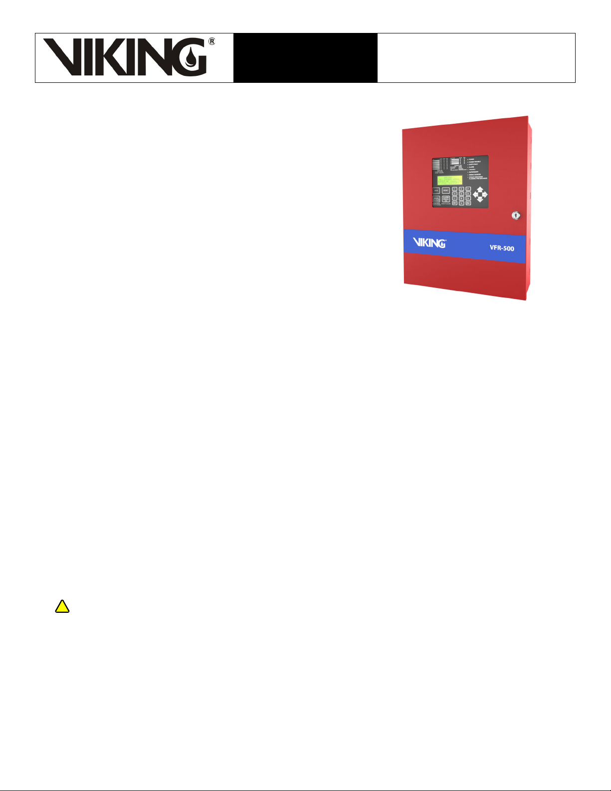
Panel Model VFR-500
1. DESCRIPTION
The Viking VFR-500 is a microprocessor-based multi-hazard,
releasing control panel for preaction, deluge, and
water-based extinguishing systems or for agent extinguishing
systems. The VFR-500 may also be used as a stand-alone
fire control panel.
This model is Underwriters Laboratory listed and complies
with the following: UL Standard 864, ULC S527, and FM. It is
also RoHS Compliant.
The VFR-500 shall be installed in accordance with the
NFPA-12, NFPA-12A, NFPA-13, NFPA-15, NFPA-16,
NFPA-17, NFPA-17A, NFPA-72, NFPA-750, NFPA 2001, and
the Canadian Electrical Code Part 1 C22.1, ULC-S524.
For complete product information, refer to the VFR-500
Conventional Releasing Panel Installation, Operations and
Programming Manual (Manual #5403789).
Features
• Multi-hazard operation
• Supervised microprocessor
• 80-character LCD display
• Customizable banner messages and zone
descriptions
• On-board, menu-driven programming controls
• Protected releasing circuits (against false
activations)
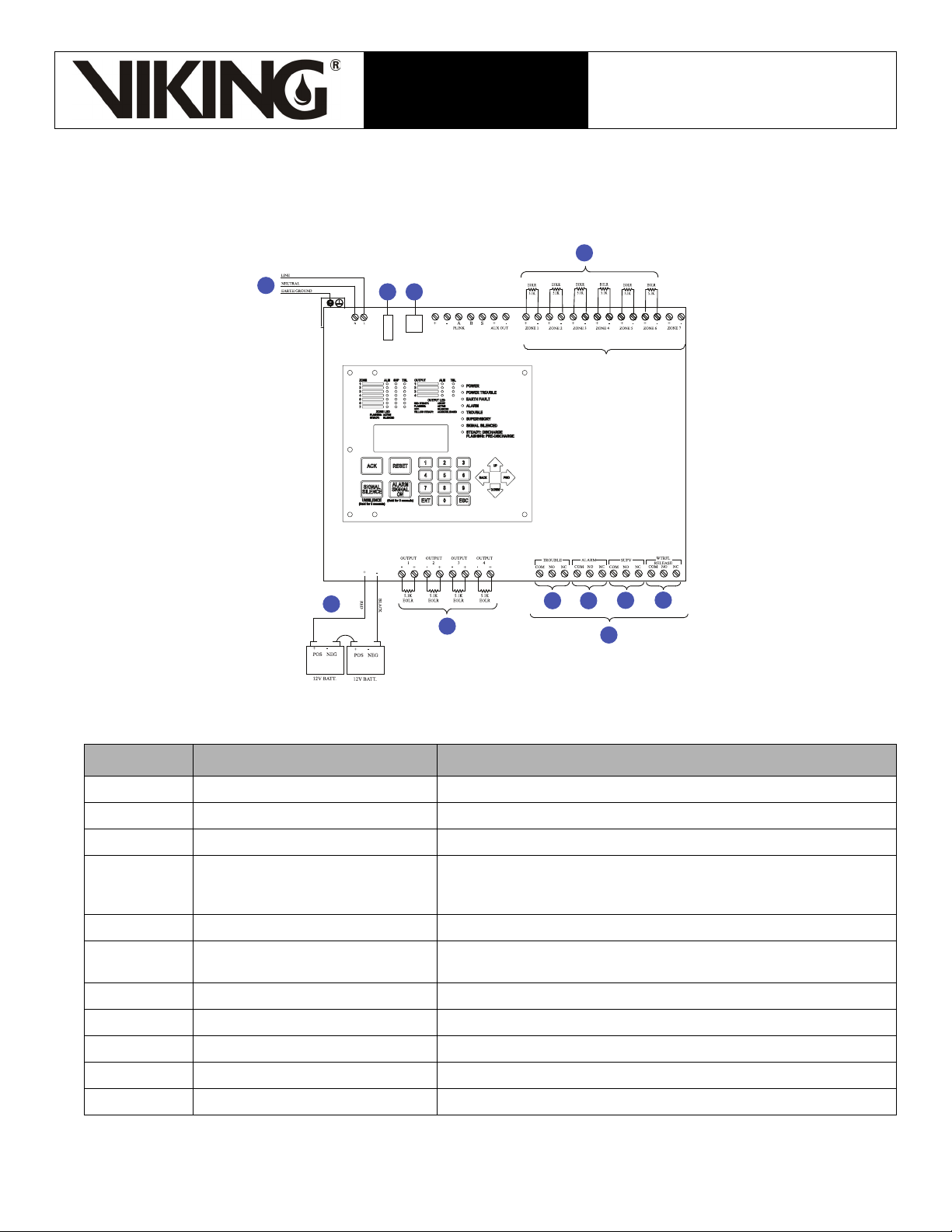
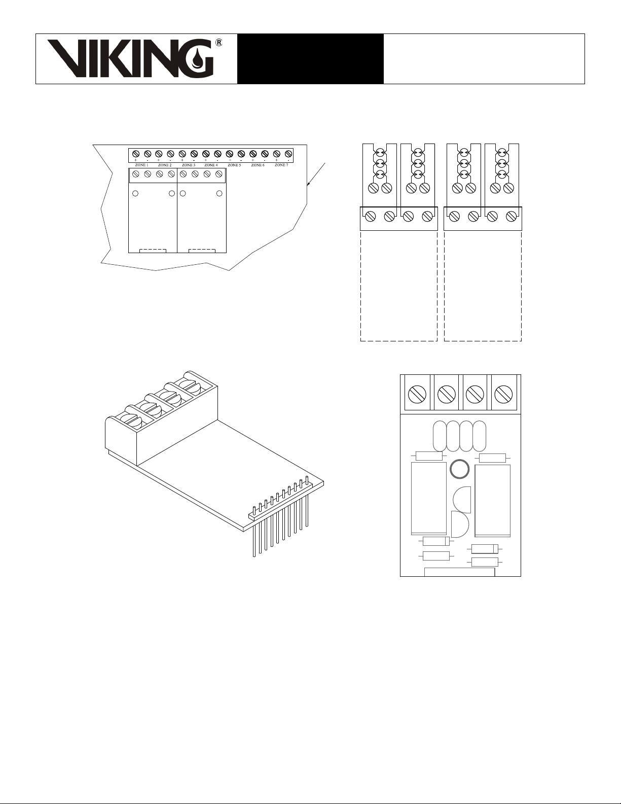
• Seven (7) Class B initiating circuits
• Two (2) Class B supervisory circuits**
• Four Class B output circuits
• Programmable cross zoning
• Continuous or timed discharge
• 4,000-event history buffer
• Walk test with automatic time-out
• Ethernet connection for programming and
non-listed communication
• Email support (system status and events)
• Customizable reminder emails
• Alarm, trouble, supervisory, and
waterflow/discharge confirmation relays
• Optional Class A output zone module
• 35 standard programs in panel memory
• Password-protection
• 24-hour clock
• Supervised remote annunciator output (up to
31 per system)
• Auxiliary 24 VDC Power (constant and
resetable)
• Lockable steel cabinet with optional trim bezel
• 120 or 220 VAC primary power
• Houses two (2) 12AH batteries (up to 90 hours
of stand-by power)
• Wide compatibility range (including spot heat
detectors, smoke detectors, and linear heat
detectors)
**Can be used for supervisory, tamper, low air, high air, or abort switch.
Installing or servicing fire protection products such as sprinklers, valves, piping etc. can expose you
to chemicals including lead, which is known to the state of California to cause cancer and birth
defects or other reproductive harm. For more information, go to www.P65Warnings.ca.gov.