manuals.online logo
Brands
  1. Home
  2. •
  3. Brands
  4. •
  5. Viking
  6. •
  7. Controllers
  8. •
  9. Viking RC-3 Instructions for use

Viking RC-3 Instructions for use

Remote Control of:
• High security building entry systems
• Door strikes and gates in conjunction with
doorboxes (W-1000, etc.)
• Signs, lights, cameras, sprinklers, motors
• Other contact controlled equipment
• Can also be used as an emergency dialer for
alarm systems, etc.
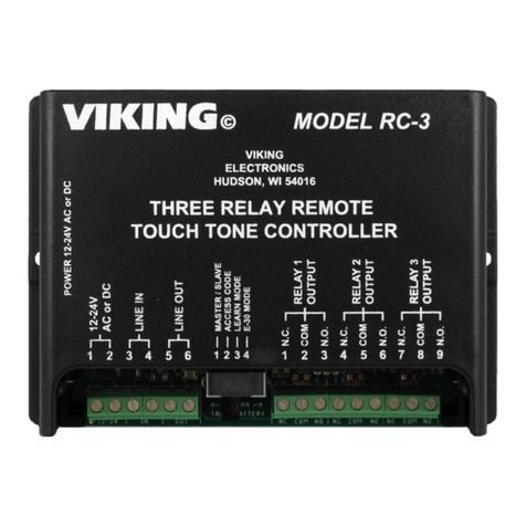
RC-3
RC-3
3 Relay Remote Touch
Tone Controller
May 26, 2005
The RC-3 enables a standard Touch Tone
phone to control up to 3 maintained ON, main-
tained OFF, or momentary relay contacts from
a remote location. The RC-3 is fully user pro-
grammable and uses non-volatile E2memory.
Up to three RC-3’s can be daisy chained on
the same line to control up to nine relays.
The RC-3 features switchable 12V talk battery
allowing easy installation on the trunk port. In
addition, the unit can be connected directly to
a C.O. line or analog PABX/KSU station.
Control 1 to 9 Relays Remotely
P
Ph
ho
on
ne
e.
..
..
.7
71
15
5.
.3
38
86
6.
.8
88
86
61
1
h
ht
tt
tp
p:
:/
//
/w
ww
ww
w.
.v
vi
ik
ki
in
ng
ge
el
le
ec
ct
tr
ro
on
ni
ic
cs
s.
.c
co
om
m
• User Touch Tone programmable
• Non-volatile E2memory
• 12 digit alarm activated pulse dialer
• 6 digit security code (to access programming)
• 6 digit access code (disable or enable for
additional control security)
• Switchable 12V talk battery
• Relay interrogation tones
• Programmable relay time delays
• Cascade up to three RC-3’s to control up to
nine relays
• Programmable ring delay before answering
• Status LED’s for relays 1, 2, 3 and the
answer relay
• One power adaptor can power up to three
units
Power: 120V AC/12V DC 500mA UL listed adapter provided
Shipping Weight: 3.6 kg (8 lbs)
Dimensions: 133mm x 89mm x 44mm (5.25” x 3.5” x 1.75”)
Environmental: 0°C to 32°C (32°F to 90°F) with 5% to 95%
non-condensing humidity
Pulse Dialing Speed: 10 pps
Talk Battery Output: 12V DC minimum (15V nominal)
Relay contact ratings: .5A @ 125V AC/1A @ 30V DC
On hook time between alarm dialing: 2.5 seconds
Connections: (2) RJ11 jacks, 10 position screw terminal strip
P
Pr
ra
ac
ct
ti
ic
ce
e
T
TE
EL
LE
EC
CO
OM
MS
SO
OL
LU
UT
TI
IO
ON
NS
SF
FO
OR
RT
TH
HE
E2
21
1S
ST
TC
CE
EN
NT
TU
UR
RY
Y
TECHNICAL
TECHNICAL
F
Fe
ea
at
tu
ur
re
es
s
S
Sp
pe
ec
ci
if
fi
ic
ca
at
ti
io
on
ns
s
The RC-3 also features a built in pulse dialer activated by a contact closure from an
alarm system, temperature sensor, etc. The RC-3 will dial the number up to three times
sending alert tones indicating an emergency.
A
Ap
pp
pl
li
ic
ca
at
ti
io
on
ns
s
i
in
nf
fo
o@
@v
vi
ik
ki
in
ng
ge
el
le
ec
ct
tr
ro
on
ni
ic
cs
s.
.c
co
om
m
I
In
ns
st
ta
al
ll
la
at
ti
io
on
n
B. Expanding To Control From 4 to 9 Relays
Two or three RC-3’s can be daisy chained to the same line to control 1 to 9 relays. One “master” RC-3 can power up
to two “slave” RC-3’s by daisy chaining power from terminals 9 and 10. The master/slave shunt should be removed
from each slave unit. This will disable each slave’s ring detection and will also reduce the total REN loading on the line.
Note: Each unit must be programmed separately before connecting to the same line (see Programming), and must be programmed
with the same access code. Battery Feed switches on the slave units must be in the “OFF” position.
A. Entering the Programming Mode
a. Connect a Touch Tone phone to the RJ-OUT jack.
b. Place the BATTERY FEED switch in the ON position.
c. Come off hook.
d. Enter ✱and the security code (factory set to 845464).
e. Two beeps should be heard. You are now in the programming mode.
VIKING©
MODEL RC-3
POWER 12 VDC
1 2 3 4 5 6 7 8 9 10
3 RELAY REMOTE
TOUCH TONE CONTROLLER
12V TALK
BATTERY FEED
RJ-IN RJ-OUT
OFF ON
VIKING
ELECTRONICS
HUDSON,WI 54016
RELAY 1
RELAY 2
RELAY 3
ALARM
INPUT
12 VDC
- +
Connect to pins 9 & 10 to power units
2 and 3.
Dry contact closure from alarm system
(to initiate dialing)
N/C
COM
N/O (factory setting)
COM
N/O
Viking Doorbox
(W-2000A shown)
or
Call
VIKING©
12V TALK BATTERY FEED SWITCH - Must be in
left (OFF) position when connecting to a
C.O./Station. Place in right (ON) position when
connecting to a trunk input of a phone system.
RJ-OUT - Paralleled with RJ-IN for connecting to
other telecom equipment (phone, second RC-3, etc.)
N/O
COM
C.O. Line or
Analog
PABX/KSU
Station
Unused
Trunk
Input of
PABX/KSU
P
Pr
ro
og
gr
ra
am
mm
mi
in
ng
g
1. To Locally Program the RC-3 (without connecting the unit to a telco line)
a. Place the BATTERY FEED switch in the OFF position.
b. Connect the RJ-IN jack to your C.O. line or analog PABX/KSU extension.
c. Call into the unit.
d. When the unit answers, two beeps should be heard.
e. Enter ✱and the security code (factory set to 845464).
f. Two beeps should be heard. You are now in the programming mode.
Note: Upon entering the programming mode (or after a power outage without battery back-up), all relays will return
to their programmed state.
2. To Remotely Program the RC-3
VIKING©
MODEL RC-3
POWER 12 VDC
1 2 3 4 5 6 7 8 9 10
3 RELAY REMOTE
TOUCH TONE CONTROLLER
12V TALK
BATTERY FEED
RJ-IN RJ-OUT
OFF ON
VIKING
ELECTRONICS
HUDSON,WI 54016
RELAY 1
RELAY 2
RELAY 3
ALARM
INPUT
12 VDC
- +
VIKING©
MODEL RC-3
POWER 12 VDC
1 2 3 4 5 6 7 8 9 10
3 RELAY REMOTE
TOUCH TONE CONTROLLER
12V TALK
BATTERY FEED
RJ-IN RJ-OUT
OFF ON
VIKING
ELECTRONICS
HUDSON,WI 54016
RELAY 1
RELAY 2
RELAY 3
ALARM
INPUT
12 VDC
- +
VIKING©
MODEL RC-3
POWER 12 VDC
1 2 3 4 5 6 7 8 9 10
3 RELAY REMOTE
TOUCH TONE CONTROLLER
12V TALK
BATTERY FEED
RJ-IN RJ-OUT
OFF ON
VIKING
ELECTRONICS
HUDSON,WI 54016
RELAY 1
RELAY 2
RELAY 3
ALARM
INPUT
12 VDC
- +
Master/Slave Shunt
In Place
Master/Slave Shunt
Removed
Master/Slave Shunt
Removed
Master RC-3
(programmed relay bank
1 for relays 1, 2 and 3)
Slave RC-3
(programmed relay bank
2 for relays 4, 5 and 6)
Slave RC-3
(programmed relay bank
3 for relays 7, 8 and 9)
A. Single RC-3 Installation
C. Quick Programming Features
B. Security Code
The Security Code number allows the user/installer to change the unit’s programming. To enter your own Security
Code, follow the steps below:
1. Enter the programming mode (see section Aabove), two beeps should be heard.
2. Enter your new 6-digit security code (0-9), then “#22”, two beeps should be heard.
Your personal Security Code number is now programmed. The Security Code can be reprogrammed as often as need-
ed (see Programming, section C). Important: The Security Code and the Access Code can NOT be the same!
Set Relay 1 to normally closed .........................................................................................
Set Relay 2 to normally closed .........................................................................................
Set Relay 3 to normally closed (terminals 5 & 6) ..............................................................
Set Relay 1 to normally open (factory setting) ..................................................................
Set Relay 2 to normally open (factory setting) ..................................................................
Set Relay 3 to normally open (terminals 5 & 6, factory setting) ........................................
Timed relay activation (2 digits = 01-09 x .5 sec or 6 digits = 00-08 hrs, 00-59 min, 00-59 sec) .............
Alarm pulse dial number entry .........................................................................................
To add a 4 second pause at any point in the alarm number dialing string .........................
Alarm dialing enabled (factory setting) .............................................................................
Alarm dialing disabled ......................................................................................................
Ring delay before answering (1 to 31 rings, factory set to 2) ............................................
Security Code (for entering programming), 6 digits, 0-9 (factory set to 845464) ..............
Access Code, 6 digits, 0-9 (factory set to 123456) ...........................................................
Enable Access Code (factory setting) ..............................................................................
Disable Access Code .......................................................................................................
Set relay bank number (when using two or three RC-3’s on the same line) .....................
Halt and start command over ...........................................................................................
Enter
Digits
2 or 6 digits
0-12 digits
01-31
6 digits
6 digits
✱#
then
then
then
then
then
then
Memory
Location
✱1
✱2
✱3
✱4
✱5
✱6
#1 +1-3
#00
✱7
✱✱
✱0
#21
#22
#23
✱8
✱9
1, 2 or 3
##
-then-
D. Confirmation Beeps During Programming
There are three types of beeps during programming. A double beep indicates a valid entry. A single beep followed by
a double beep indicates an invalid entry or error. Four beeps indicates either 20 seconds have elapsed from the last
Touch Tone entered or the wrong Security Code was entered. When programming remotely, the RC-3 will output four
beeps then hang up if the 20 second Touch Tone time out is exceeded or the wrong security code is entered, you must
then re-call the unit and re-enter programming. If you are programming locally, you can re-enter programming simply
by re-entering ✱and your Security Code.
To Program...
...Relay 1 for a timed activation of 1.5 seconds
...Relay 3 for a timed activation of 5 hours, 17 minutes and 39 seconds
...the RC-3 to pulse dial 9, 4 second pause, 555-1234 when a contact
closure is made on the Alarm terminals across 8 and 9
...your access code to 543210
Enter Digits
03, #1, 1 (two beeps)
05, 17, 39, #1, 3 (two beeps)
9, ✱7, 5551234, #00 (two beeps) ✱✱ (two beeps)
543210, #23 (two beeps) ✱8 (two beeps)
E. Programming Examples
O
Op
pe
er
ra
at
ti
io
on
n
A. Immediate Access Mode
Go off hook on the C.O. line or access the trunk port of your phone system that the RC-3 is connected to. With the
Access Code disabled you can now immediately enter the Touch Tone commands for controlling the RC-3’s relay out-
puts (see Operation, section Cbelow). Note: If the time between key strokes exceeds 20 seconds, four beeps will
be heard but you may continue to enter commands.
B. Remote Access Mode
Call the RC-3 from a remote location. The unit will answer and give two beeps after the programmed ring delay (see
Programming section C). Enter a ✱and the six digit Access Code (if enabled), two beeps should be heard for the cor-
rect Access Code entry. You can now enter the Touch Tone commands for controlling the RC-3’s relay outputs. Note:
You can continue to enter Touch Tone commands as long as the time between key strokes does not exceed 20 sec-
onds. If you exceed 20 seconds, four beeps will be heard and the unit will hang up.
Description
1. Relay 2 activating from a remote location with the access code
programmed to 123456 and enabled
2. Starting the timed activation of Relay 3 locally, with the RC-3 on an
unused trunk input of your phone system, access code disabled
3. Remotely stop the RC-3 from calling you (three times if not
disabled) during an alarm sequence
Enter Digits
(two beeps) ✱123456 (two beeps) 2 1 (two beeps)
3 2
(answer phone) # (four beeps) (hang up)
Due to the dynamic nature of the product design, the information contained in this document is subject to change without notice. Viking Electronics, and its affiliates and/or
subsidiaries assume no responsibility for errors and omissions contained in this information. Revisions of this document or new editions of it may be issued to incorporate
such changes.
Fax Back Doc 165 ZF300350 Rev DPrinted in the U.S.A.
P
Pr
ro
od
du
uc
ct
tS
Su
up
pp
po
or
rt
tL
Li
in
ne
e.
..
..
.7
71
15
5.
.3
38
86
6.
.8
86
66
66
6F
Fa
ax
xB
Ba
ac
ck
kL
Li
in
ne
e.
..
..
.7
71
15
5.
.3
38
86
6.
.4
43
34
45
5
D. RC-3 Commands
To control the RC-3’s operation, enter one of the following commands:
To force the RC-3 to hang-up (four beeps) .................................................................................................................
To start a timed activatation for all relays (two beeps) ................................................................................................
To halt and remove the last digit entry (three beeps) ..................................................................................................
To disable the alarm dialing sequence and force the RC-3 to hang-up (four beeps) ...................................................
01
02
#
#
Enter
E. Confirmation Beeps During Operation
There are four types of beeps you will hear while controlling the RC-3. A single beep should be heard after de-acti-
vating relays, two beeps after activating relays, three beeps after a “halt” command or incorrect entry (error), and four
beeps if 20 seconds have elapsed between Touch Tone commands or a forced hang-up command is entered.
F. Alarm Dialing (Loop start C.O./Centrex line and PABX station applications only)
The RC-3 can be used as an emergency dialer, activated by a continuous contact closure between terminals 8 & 9.
Five seconds after the closure is made, the RC-3 will pulse dial (10 pps) the programmed number, hold the line for
approximately two minutes, then hang up and repeat this sequence two more times. This sequence can be halted by
entering a Touch Tone # locally or at the dialed location. The RC-3 will output a single beep every 5 seconds while the
alarm is set (Terminals 8 & 9 are closed), indicating the alarm condition. The RC-3 requires a minimum of a 5 second
reset or open between terminals 8 and 9 before initiating a second alarm dialing sequence. Note: The RC-3 will not
initiate a alarm dialing sequence during user operation or programming. Therefore, a continuous contact closure is rec-
ommended. Due to the RC-3’s 12 digit (maximum) alarm dialing number, the RC-3 should not be placed behind a PABX
when long distance dialing is required.
F. Relay and Answer LED’s
The relay status LED’s are labeled RELAY 1, RELAY 2, RELAY 3 and light whenever relays 1, 2 or 3 are closed. The
fourth LED is labeled ANSWER. This LED lights when the RC-3 has answered or seized the line and will flash during
alarm dialing.
G. Operating Examples
O
Ot
th
he
er
rA
Ap
pp
pl
li
ic
ca
at
ti
io
on
ns
s
The RC-3 can remotely control three door
strikes from any station on your PABX.
After verbal confirmation from the door-
box, the person on the control phone sim-
ply has to access the trunk or station con-
nected to the RC-3, then enter the relay
activation code for that door strike.
C. Relay Commands
To use the RC-3’s relay commands, enter the relay number (1-3 for a single unit or 1-9 for multiple units) then enter
one of the following commands:
To activate a relay continuously (latch) ..........................................................................................................
To de-activate a latched relay ........................................................................................................................
To activate a relay momentarily (timed activation - factory set to 5 seconds)) ................................................
To interrogate relay status (one beep = de-activated, two beeps = activated) ................................................
1
0
2
3
Enter
VIKING©
MODEL RC-3
POWER 12 VDC
1 2 3 4 5 6 7 8 9 10
3 RELAY REMOTE
TOUCH TONE CONTROLLER
12V TALK
BATTERY FEED
RJ-IN RJ-OUT
OFF ON
VIKING
ELECTRONICS
HUDSON,WI 54016
RELAY 1
RELAY 2
RELAY 3
ALARM
INPUT
12 VDC
- +
Doorbox 3
(W-2000A shown)
Unused
Trunk
Input of
PABX/KSU
Call
VIKING©
Door Strike 1
Door Strike 2
Door Strike 3
Call
VIKING©
Call
VIKING©
Doorbox 2
(W-2000A shown)
Doorbox 1
(W-2000A shown)
1-9
1-9
1-9
1-9
Relay

Other manuals for RC-3

1

Other Viking Controllers manuals

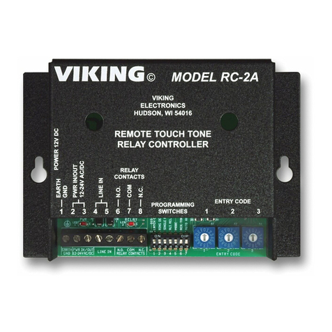
Viking RC-2A Instructions for use

Viking

Viking RC-2A Instructions for use

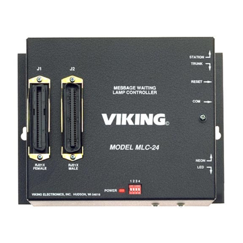
Viking MLC-24 Instructions for use

Viking

Viking MLC-24 Instructions for use

Viking RC-2A Instructions for use

Viking

Viking RC-2A Instructions for use

Viking SRC-1 Instructions for use

Viking

Viking SRC-1 Instructions for use

Viking CTG-2A User manual

Viking

Viking CTG-2A User manual

Viking SC-911 Instructions for use

Viking

Viking SC-911 Instructions for use

Viking C--250 Instructions for use

Viking

Viking C--250 Instructions for use

Viking RC-3 Instructions for use

Viking

Viking RC-3 Instructions for use

Viking SLP-1 Instructions for use

Viking

Viking SLP-1 Instructions for use

Viking BTC-1 User manual

Viking

Viking BTC-1 User manual

Viking C-250 Instructions for use

Viking

Viking C-250 Instructions for use

Viking SRC-1 User manual

Viking

Viking SRC-1 User manual

Viking SC-911 Instructions for use

Viking

Viking SC-911 Instructions for use

Viking SV-5W Instructions for use

Viking

Viking SV-5W Instructions for use

Viking C-250 Instructions for use

Viking

Viking C-250 Instructions for use

Viking SLP-4 Instructions for use

Viking

Viking SLP-4 Instructions for use

Viking RC-4A User manual

Viking

Viking RC-4A User manual

Viking RC-4 Instructions for use

Viking

Viking RC-4 Instructions for use

Viking RC-2A User manual

Viking

Viking RC-2A User manual

Viking SC-911 Instructions for use

Viking

Viking SC-911 Instructions for use

Viking C-1000B User manual

Viking

Viking C-1000B User manual

Viking CTG-2A User manual

Viking

Viking CTG-2A User manual

Viking VC-1000 Instructions for use

Viking

Viking VC-1000 Instructions for use

Viking SLP-1 Instructions for use

Viking

Viking SLP-1 Instructions for use

Popular Controllers manuals by other brands

Digital Monitoring Products X1 Series quick start guide

Digital Monitoring Products

Digital Monitoring Products X1 Series quick start guide

AMX AutoPatch quick start guide

AMX

AMX AutoPatch quick start guide

vacuubrand CVC 3000 Instructions for use

vacuubrand

vacuubrand CVC 3000 Instructions for use

ComfortClick Jigsaw manual

ComfortClick

ComfortClick Jigsaw manual

MKS 640A/641A manual

MKS

MKS 640A/641A manual

Cypress CapSense CY8CMBR2044 Design guide

Cypress

Cypress CapSense CY8CMBR2044 Design guide

Tekmar Mixing Control 354 Data brochure

Tekmar

Tekmar Mixing Control 354 Data brochure

Yaesu G-550 instruction manual

Yaesu

Yaesu G-550 instruction manual

AMX NXV-CPI quick start guide

AMX

AMX NXV-CPI quick start guide

KUSSMAUL 091-84-GM1 manual

KUSSMAUL

KUSSMAUL 091-84-GM1 manual

SMC Networks LEC-W2 installation manual

SMC Networks

SMC Networks LEC-W2 installation manual

Terasic Altera Dual-XAUI user manual

Terasic

Terasic Altera Dual-XAUI user manual

MKS Mass-Flo 1679B instruction manual

MKS

MKS Mass-Flo 1679B instruction manual

SOMFY animeo WM installation guide

SOMFY

SOMFY animeo WM installation guide

ABB MotiFlex e180 Quick installation guide

ABB

ABB MotiFlex e180 Quick installation guide

Epever Tracer-BN Series MPPT user manual

Epever

Epever Tracer-BN Series MPPT user manual

Hitachi PSC-A32MN Installation and operation manual

Hitachi

Hitachi PSC-A32MN Installation and operation manual

Omron SYSMAC CS1W-EIP21 Operation manual

Omron

Omron SYSMAC CS1W-EIP21 Operation manual

manuals.online logo
manuals.online logoBrands
  • About & Mission
  • Contact us
  • Privacy Policy
  • Terms and Conditions

Copyright 2025 Manuals.Online. All Rights Reserved.