manuals.online logo
Brands
  1. Home
  2. •
  3. Brands
  4. •
  5. Viking
  6. •
  7. Cooktop
  8. •
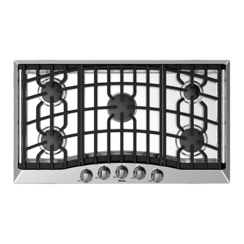
  9. Viking Professional Custom VGRT530-4BSS User manual

Viking Professional Custom VGRT530-4BSS User manual

Other manuals for Professional Custom VGRT530-4BSS

4

This manual suits for next models

57

Other Viking Cooktop manuals

Viking Professional VGSU103-4B User guide

Viking

Viking Professional VGSU103-4B User guide

Viking VCCU106-4B User manual

Viking

Viking VCCU106-4B User manual

Viking RVGC3361 User manual

Viking

Viking RVGC3361 User manual

Viking F20111C User manual

Viking

Viking F20111C User manual

Viking Professional VICU266-6B User manual

Viking

Viking Professional VICU266-6B User manual

Viking Designer DECU105 User manual

Viking

Viking Designer DECU105 User manual

Viking Designer DECU1054B User manual

Viking

Viking Designer DECU1054B User manual

Viking RDECU2065BSB User manual

Viking

Viking RDECU2065BSB User manual

Viking Designer DECU105 User manual

Viking

Viking Designer DECU105 User manual

Viking VGRT5606GQSS User manual

Viking

Viking VGRT5606GQSS User manual

Viking RVEC3305B User manual

Viking

Viking RVEC3305B User manual

Viking RDGSU2005B User manual

Viking

Viking RDGSU2005B User manual

Viking VGRT302-4B Series User manual

Viking

Viking VGRT302-4B Series User manual

Viking VICU2064BSB User manual

Viking

Viking VICU2064BSB User manual

Viking Designer DETU200-4B User manual

Viking

Viking Designer DETU200-4B User manual

Viking VGWT User manual

Viking

Viking VGWT User manual

Viking Built-In Electric Cooktops User manual

Viking

Viking Built-In Electric Cooktops User manual

Viking RVEC3305B User manual

Viking

Viking RVEC3305B User manual

Viking CVECU530 User manual

Viking

Viking CVECU530 User manual

Viking DGVU2004B-30 User manual

Viking

Viking DGVU2004B-30 User manual

Viking VGWT240SS User manual

Viking

Viking VGWT240SS User manual

Viking VICU206 User manual

Viking

Viking VICU206 User manual

Viking F20532A User manual

Viking

Viking F20532A User manual

Viking VGSC4876GSS User manual

Viking

Viking VGSC4876GSS User manual
Popular Cooktop manuals by other brands

Fisher & Paykel CE302CBX2 manual

Fisher & Paykel

Fisher & Paykel CE302CBX2 manual

Whirlpool GJC3634RB00 parts list

Whirlpool

Whirlpool GJC3634RB00 parts list

Whirlpool ACH7324/BLV Use, care and installation guide

Whirlpool

Whirlpool ACH7324/BLV Use, care and installation guide

Frigidaire Professional FPDF4085KF Important safety instructions

Frigidaire

Frigidaire Professional FPDF4085KF Important safety instructions

Bonnet OPTIMUM 700 Technical instructions

Bonnet

Bonnet OPTIMUM 700 Technical instructions

Jenn-Air JGCP430 installation instructions

Jenn-Air

Jenn-Air JGCP430 installation instructions

Bompani BO374AA/E User instructions

Bompani

Bompani BO374AA/E User instructions

Kleenmaid cooking GCTK9011 Instructions for use and warranty details

Kleenmaid

Kleenmaid cooking GCTK9011 Instructions for use and warranty details

Waldorf RN8603E-B Technical data sheet

Waldorf

Waldorf RN8603E-B Technical data sheet

Whirlpool SMP658CNEIXL quick guide

Whirlpool

Whirlpool SMP658CNEIXL quick guide

Electrolux E36IC80ISS - 36" Induction Cooktop Wiring diagram

Electrolux

Electrolux E36IC80ISS - 36" Induction Cooktop Wiring diagram

Wolf CI243C/B Use and care guide

Wolf

Wolf CI243C/B Use and care guide

Fulgor Milano F5PGK305S1 installation instructions

Fulgor Milano

Fulgor Milano F5PGK305S1 installation instructions

Wells WV-2HFG owner's manual

Wells

Wells WV-2HFG owner's manual

Samsung NA36N9755 installation manual

Samsung

Samsung NA36N9755 installation manual

Miele KM 404 operating instructions

Miele

Miele KM 404 operating instructions

Lacor 69562 Instructions for use and maintenance

Lacor

Lacor 69562 Instructions for use and maintenance

Keating Of Chicago MG-2 manual

Keating Of Chicago

Keating Of Chicago MG-2 manual

manuals.online logo
manuals.online logoBrands
  • About & Mission
  • Contact us
  • Privacy Policy
  • Terms and Conditions

Copyright 2025 Manuals.Online. All Rights Reserved.

Viking Range Corporation
111 Front Street
Greenwood, Mississippi 38930 USA
(662) 55-1200
For product information
call 1-888-VIKING1 (8 5- 6 1)
or visit the Viking Web site at
vikingrange.com
F1 8K EN (020211)
Viking Installation Guide
Range/Rangetop Rear Trim Accessories
& Range Curb Base Fronts
32
A
X
(Illustration II)
Grasp the trim on each end and carefully place in the channels (B) located at each rear corner of the
product. Align the screw holes (A) at each end of the trim device with the holes (A) in each rear channel
of the product. Secure with the enclosed screws.
A
BB
B
A
B
RANGETOP
REAR VIEW
RANGE REAR
VIEW
(Illustration I)
HIGH SHELF
Rear Trim Accessories Rear Trim Accessories
Backguards come equipped with Nylon Spacers (See Figure 1), which are needed to space the
range off a combustible wall a prescribed safe distance.
Note: If the back wall is Non-Combustible, these space s can be emoved. (See Figu e 2)
These spacers can also be removed if used with any of the models listed below:
•30”, 36” and 8” VGCC
•VDSC530
•VDSC536
•VGRT530
•VGRT536
ATTACHING REAR TRIM (Illustration I)
ATTACHING SHELF ON HIGH-SHELF (Illustration II)
All rear trim devices are installed in the same basic way.
Place the top rolled edge (X) over the front lip of the high-shelf back trim and secure with the
enclosed screws, two at each end.
WARNING
To reduce the risk of fire or injury to
persons, check to make sure all packaging
has been removed from the outside and
inside parts of the rear trim device before
installing. MAKE SURE ALL CORRUGATED
MATERIAL IS REMOVED FROM INSIDE
THE HIGH SHELF.
NOTE: High shelf is al eady installed on
Designe models.
ATTACHING BACKGUARD (Illustration III)
Figure 1
(Illustration III)
Figure 2
On VGSC530, VGSC536 and VGSC5 8 models there is a regulator cover supplied with the
backguard that must be attached to the oven, with the supplied screws, before the backguard
is attached. (See Figure 3)
Figure 3
*If you have one of these models, the
spacers are not required, even if with a
combustible wall.
5
Curb Bases
Alternate Curb Base View
for Custom Ranges
STANDARD CURB BASE FRONT
1. The standard curb base front (A) is completely assembled.
2. Remove the assembly from the carton and simply clip onto the front range legs.
3. The assembly is adjustable about 2” (5.1 cm) front to back so that alignment with the cabinet
toe front is possible. Loosen brackets on each side, but allow snug fit. Clip assembly onto
range legs; determine front to back setting; remove, tighten bolts, and reattach.
A
IMPORTANT: USE OF ISLAND TRIM WITH AND WITHOUT 6” (15 2 CM) CLEARANCE
Normal installation for island trim on either a range or rangetop is in an island/peninsula or where there is a
minimum clearance of 6”(15.2 cm) to any type of wall at the rear of the unit. However, agency authorization has
been received for island trim installations where a range or rangetop can be installed at zero clearance to the
rear wall as long as the wall is non-combustible. The responsibility for ensuring that the rear wall is non-
combustible and heat resistant lies with the individual owner and/or end user. Only in those cases where the
island trim is installed with 6” (15.2 cm) of minimum clearance to a rear wall, or when a truly non-combustible
material is used, will the warranty apply. In no case will Viking Range Corporation accept responsibility for any
claims which may result from heat damage against a rear wall, including cosmetic damage. It is the total
responsibility of the owner/end user to ensure that the material utilized in such applications is not only non-
combustible, but is also truly heat-resistant.
Once you determine whether or not your product needs the provided spacers, the backguard is ready
to be attached.
Simply slide the backguard down onto the rear of the unit and attach using the ( ) screws provided.
(See Figure 5)
A
Figure 5
Rear Trim Accessories
Custom VGIC ranges and 60” VGCC ranges require that two 1” standoff spacers be attached to the
back of the range when using a range with a backguard against a combustible surface. (See Figure )
Figure
Impo tant Note: The range must be installed as specified in the range installation guide for proper
airflo hen using the standard curb base.
76
CUSTOM CURB BASE FRONT
1. Remove the standard curb base front assembly from the carton.
2. Remove the front (A) from the mounting assembly (B).
3. Attach locally supplied front (C) to the mounting assembly (B) and simply clip onto the front
range legs.
Impo tant Note: The locally supplied front must not be any taller than 3-1/8” (7.9 cm) tall. Fronts taller
than 3-1/8” (7.9 cm) could obstruct the airflo .
. The assembly is adjustable about 2” (5.1 cm) front to back so that alignment with the cabinet
toe front is possible. Loosen brackets on each side, but allow snug fit. Clip assembly onto
range legs; determine front to back setting; remove, tighten bolts, and reattach.
B
C
Curb Bases
A
COUNTERTOP REAR TRIM
1. Locate screw hole openings (A) on back of island trim near the top.
2. Align screw hole openings on countertop rear trim with the ones on the back of the island trim.
3. Attach rear trim to island trim with enclosed screws.
Impo tant Note: The range must be installed as specified in the range installation guide for proper
airflo hen using the custom curb base.
Curb Bases