manuals.online logo
Brands
  1. Home
  2. •
  3. Brands
  4. •
  5. Viking
  6. •
  7. Cooktop
  8. •
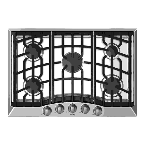
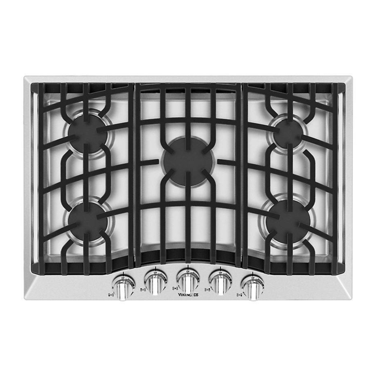
  9. Viking DGSU1004BSS User manual

Viking DGSU1004BSS User manual

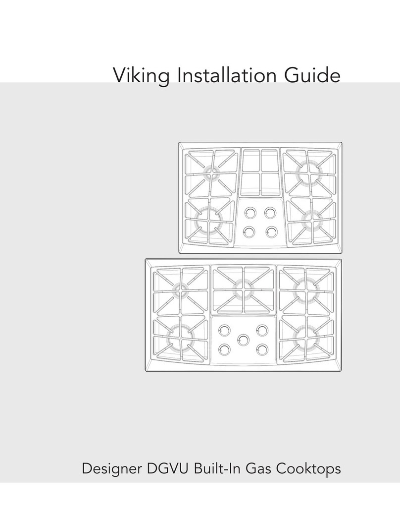
Viking Installation Guid
Prof ssional and D sign r
Built-In Gas Cooktops
Viking Rang Corporation
111 Front Str t
Gr nwood, Mississippi 38930 USA
(662) 455-1200
For product information,
call 1-888-VIKING1 (845-4641)
or visit th Viking W b sit at
vikingrang .com
F20562D EN (121610)
®
IMPORTANT
• B for b ginning, pl as r ad th s
instructions compl t ly and car fully.
•DO NOT r mov p rman ntly affix d
lab ls, warnings, or plat s from product.
This may void th warranty.
• All local and national cod s and
ordinanc s must b obs rv d. Installation
must conform with local cod s or in th
abs nc of cod s, th National Fu l Gas
Cod ANSI Z223.1 NFPA54-lat st dition.
• Th install r must l av th s instructions
with th consum r for local insp ctor’s us
and for futur r f r nc .
Installation of any gas-fir d quipm nt
should b mad by a lic ns d plumb r. A
manual gas shut-off valv must b install d
in th gas supply lin ah ad of th cooktop
in th gas str am for saf ty and as of
s rvic .
In Canada: Installation must b in
accordanc with th curr nt CAN/CGA
B149.1 & 2 Gas Installation cod s and/or
local cod s. El ctrical installation must b in
accordanc with th curr nt CSA C22.1
Canadian El ctrical Cod s Part 1 and/or
local cod s.
In Massachusetts: All gas products must b
install d by a “Massachus tts” lic ns d
plumb r or gasfitt r. A “T” typ handl
manual valv must b install d in th gas
supply lin to th applianc .
3
–Please Read and Follow
Your safety and the safety of others is
very important.
We have provided many important safety
messages in this manual and on your
appliance. ALWAYS read and obey all
safety messages.
This is the safety alert symbol. This
symbol alerts you to hazards that
can kill or hurt you and others.
All safety messages will be preceded by
the safety alert symbol and the word
“DANGER,” “WARNING” or “CA TION.”
These words mean:
Hazards or unsafe practices
which WILL result in severe personal
injury or death
DANGER
Hazards or unsafe practices
which COULD result in severe personal
injury or death
Hazards or unsafe practices which
COULD result in minor personal injury
or property damage.
All safety messages will identify the
hazard, tell you how to reduce the chance
of injury, and tell you what can happen if
the instructions are not followed.
WARNING
CAUTION
Tabl of Cont nts
Warnings & Important Saf ty Instructions _______________________________________________3
Dim nsions (VGSU Prof ssional) _______________________________________________________6
Sp cifications (VGSU Prof ssional) _____________________________________________________7
Dim nsions (DGSU D sign r) _________________________________________________________8
Sp cifications (DGSU D sign r) _______________________________________________________9
Cutout Dim nsions _________________________________________________________________10
Cutout Dim nsions (VGSU Cooktop ov r Singl El ctric Ov n)___________________________11
Cutout Dim nsions (DGSU Cooktop ov r Singl El ctric Ov n) __________________________12
Cl aranc Dim nsions (Proximity to Cabin ts)__________________________________________13
Cl aranc Dim nsions (Wood/Composit Ov rlay) _____________________________________14
El ctrical & Gas R quir m nts _______________________________________________________15
G n ral Information ________________________________________________________________17
Installation_________________________________________________________________________18
Optional Gask t Installation ______________________________________________________18
Gas & El ctrical Conn ction______________________________________________________18
VGSU Brack t Installation ________________________________________________________19
DGSU Brack t Installation ________________________________________________________19
Final Pr paration ___________________________________________________________________20
P rformanc Ch cklist ______________________________________________________________20
S rvic & R gistration _______________________________________________________________21
2
IMPORTANT
5
–Please Read and FollowIMPORTANT
4
–Please Read and Follow
FIRE/EXPLOSION
HAZARD
IF THE INFORMATION IN
THIS MAN AL IS NOT
FOLLOWED EXACTLY, A FIRE OR
EXPLOSION MAY RES LT CA SING
PROPERTY DAMAGE, PERSONAL
INJ RY, OR DEATH.
•DO NOT store or use gasoline or other
flammable vapors and liquids in the
vicinity of this or any other appliance.
• WHAT TO DO IF YOU SMELL GAS:
–DO NOT try to light any appliance.
–DO NOT touch any electrical switch.
–DO NOT use any phone in your
building.
–Immediately call your gas supplier
from a neighbor’s phone.
–Follow the gas supplier’s instructions.
–If you cannot reach your gas supplier,
call the fire department.
• Installation and service must be
performed by a qualified installer,
service agency, or the gas supplier.
DANGER
CHEMICAL HAZARD
If not installed, operated and
maintained in accordance
with the manufacturer’s
instructions, this product could expose
you to substances in fuel or from fuel
combustion which can cause death or
serious illness and which are known to
cause cancer, birth defects, or other
reproductive harm.
For example, benzene is a chemical
which is part of the gas supplied to the
cooking product. It is consumed in the
flame during combustion. However
exposure to a small amount of benzene
is possible if a gas leak occurs.
Formaldehyde and soot are byproducts
of incomplete combustion. Properly
adjusted burners with a bluish rather
than yellow flame will minimize
incomplete combustion.
WARNING
ELECTRICAL GROUNDING
INSTRUCTIONS
The cooktop must be electrically grounded
in accordance with local codes or, in the
absence of codes, with the ANSI/NFPA
No. 70-latest edition. Installation should
be made by a licensed electrician. This
appliance is equipped with a three-prong
grounding plug for your protection against
shock hazard and should be plugged
directly into a properly grounded
receptacle. DO NOT cut or remove the
grounding prong from the plug.
For personal safety, this appliance
must e properly grounded. DO NOT
under any circumstances cut or
remove the third (ground) prong from
the power plug.
WARNING
BURN HAZARD
The use of cabinets for storage above the
appliance may result in a potential burn
hazard. Combustible items may ignite,
metallic items may become hot and
cause burns. If a cabinet storage is to be
provided the risk can be reduced by
installing a range hood that projects
horizontally a minimum of 5” (12.7 cm)
beyond the bottom of the cabinets.
CAUTION
Before placing the cooktop into operation,
always check for gas leaks with a soapy
water solution or other acceptable method.
DO NOT SE AN OPEN FLAME TO
CHECK FOR LEAKS.
CAUTION
This appliance shall not be used for
space heating. This information is based
on safety considerations.
WARNING
Sp cifications (VGSU Prof ssional)
7
Dim nsions (VGSU Prof ssional)
6
21”
(53.3cm)
30-3/4”
(78.1cm)
21”
(53.3cm)
36-3/4”
(93.3cm)
1”
(2.5 cm)
2-1/2”
(6.4 cm)
5”
(12.7 cm) 13/16”
(2.1 cm)
6-19/32”
(16.7 cm)
30” Gas Cooktop
36” Gas Cooktop
Professional Gas Cooktops
Description
VGSU104 VGSU164
Ov rall width 30-3/4” (78.1 cm) 36-3/4” (93.3 cm)
Ov rall h ight from bottom
to top of grat
5” (12.7 cm)
Ov rall d pth from r ar 21” (53.3 cm)
Cutout width 26-7/8” (68.3 cm) min. to
29-7/8” (75.9 cm) max.
34-3/8” (87.3 cm) min. to
35-7/8” (91.1 cm) max.
Cutout h ight 2-1/2” (6.4 cm)
Cutout d pth 18-5/8” (47.3 cm) min. to
20-1/8” (51.1 cm)
Gas r quir m nts To fi ld conv rt from natural or LP/Propan , th orific spuds and r gulator
must b physically chang d. Ord r conv rsion kit NK2VGSU to conv rt to
natural and LPK3VGSU to conv rt to LP. Us s standard r sid ntial
1/2” (1.3 cm) I.D. gas s rvic lin .
El ctrical r quir m nts 120 VAC/60 Hz; 4 ft. (121.9 cm), 3-wir cord with ground d
3-prong plug attach d to product.
Maximum amp usag 2.0 amps
Surfac l m nt rating
L ft front
L ft r ar
C nt r front/r ar
Right front
Right r ar
16,000 Nat./15,500 LP (BTU)
(4.8 Nat./4.65 LP (kw))
12,000 Nat./11,500 LP (BTU)
(3.6 Nat./3.45 LP (kw))
N/A
6,000 Nat./5,500 LP (BTU)
(1.8 Nat./1.65 LP (kw))
8,000 Nat./7,500 LP (BTU)
(2.4 Nat./2.25 LP (kw))
16,000 Nat./15,500 LP (BTU)
(4.8 Nat./4.65 LP (kw))
12,000 Nat./11,500 LP (BTU)
(3.6 Nat./3.45 LP (kw))
12,000 Nat./11,500 LP (BTU)
(3.6 Nat./3.45 LP (kw))
6,000 Nat./5,500 LP (BTU)
(1.8 Nat./1.65 LP (kw))
8,000 Nat./7,500 LP (BTU)
(2.4 Nat./2.25 LP (kw))
Approximat
shipping w ight 67 lb. (30.2 kg) 80 lb. (36.0 kg)
Front view Right side view
Sp cifications (DGSU D sign r)
9
Dim nsions (DGSU D sign r)
8
21”
(53.3cm)
30-3/4”
(78.1cm)
21”
(53.3)
36-3/4”
(93.3cm)
30” Gas Cooktop
36” Gas Cooktop
2-1/4”
(5.7 cm)
4-3/8”
(11.1 cm)
1-3/4”
(4.5 cm)
Designer Gas Cooktops
Description
DGSU101 DGSU161
Ov rall width 30-3/4” (78.1 cm) 36-3/4” (93.3 cm)
Ov rall h ight from bottom
to top of grat
4-3/8” (11.1 cm)
Ov rall d pth from r ar 21” (53.3 cm)
Cutout width 29-1/8” (74.0 cm) min. to
29-7/8” (75.9 cm) max.
34-7/8” (88.6 cm) min. to
35-7/8” (91.1 cm) max.
Cutout h ight 3-1/8” (7.9 cm)
Cutout d pth 19-3/4” (50.2 cm)
Gas r quir m nts To fi ld conv rt from natural or LP/Propan , th orific spuds and r gulator
must b physically chang d. Ord r conv rsion kit DLPK to conv rt to LP. Us s
standard r sid ntial 1/2” (1.3 cm) I.D. gas s rvic lin .
El ctrical r quir m nts 120 VAC/60 Hz; 4 ft. (121.9 cm), 3-wir cord with ground d
3-prong plug attach d to product.
Maximum amp usag 2.0 amps
Surfac l m nt rating
L ft front
L ft r ar
C nt r
Right front
Right r ar
16,000 Nat./12,500 LP (BTU)
(4.1 Nat./4.0 LP (kw))
12,000 Nat./11,500 LP (BTU)
(3.5 Nat./2.8 LP (kw))
N/A
6,000 Nat./5,500 LP (BTU)
(1.8 Nat./LP (kw))
8,000 Nat./7,500 LP (BTU)
(2.1 Nat./LP (kw))
12,000 Nat./11,500 LP (BTU)
(3.5 Nat./2.8 LP (kw))
10,000 Nat./9,500 LP (BTU)
(2.9 Nat./LP (kw))
16,000 Nat./12,500 LP (BTU)
(4.1 Nat./4.0 LP (kw))
6,000 Nat./5,500 LP (BTU)
(1.8 Nat./LP (kw))
8,000 Nat./7,500 LP (BTU)
(2.1 Nat./LP (kw))
Approximat
shipping w ight 49 lb. (22.0 kg) 74 lb. (33.3 kg)
Front view
Cutout Dim nsions (VGSU Cooktop ov r Singl El ctric Ov n)
11
Cutout Dim nsions
10
C
BA
Note: Based on 24 deep cabinet with 3/4 backsplash.
VGSU104 VGSU164
A 26-7/8” (68.3 cm) min. to
29-7/8” (75.9 cm) max.
34-3/8” (87.3 cm) min. to
35-7/8” (91.1 cm) max.
B 18-5/8” (47.3 cm) min. to
20-1/8” (51.1 cm) max.
C 2-1/2” (6.4 cm)
DGSU101 DGSU161
A 29-1/8” (74.0 cm) min. to
29-7/8” (75.9 cm) max.
34-7/8” (88.6 cm) min. to
35-7/8” (91.1 cm) max.
B19-3/4” (50.2 cm)
C 2-1/2” (6.4 cm)
36”min.
(91.4cm)
28-1/8”
(71.4cm)
5”
(12.7cm)max.
(toekick)
28-1/2”
(72.4cm)
26-7/8”
(73.3cm)
2-1/2”
(6.4cm)min.
12-1/4”
(31.1cm)
14-5/8”
(37.2cm)
14-1/4”
(36.2cm)
14-1/4”
(36.2cm)
18-5/8”
(47.3cm)
36”min.
(91.4cm)
28-3/4”
(73.0cm)
5”
(12.7cm)max.
(toekick)
34”
(86.4cm)
34-3/8”
(87.3cm)
2-1/2”
(6.4cm)min.
16-7/8”
(42.9cm)
17-9/16”
(44.6cm)
17”
(43.2cm)
17”
(43.2cm)
18-5/8”
(47.3cm)
30”W. Cooktop (VGSU10 ) over
30”W. Electric Oven (VESO130/530)
36”W. Cooktop (VGSU16 ) over
36”W. Electric Oven (VESO166)
Note: Refer to the oven installation instructions for undercounter dimensions.
Cl aranc Dim nsions (Proximity to Cabin ts)
13
36”min.
(91.4 cm)
13”max.
(
33.0 cm)
8”min.
(20.3cm)
18”min.
(45.7cm)
A
36”min.
(91.4cm)
Proximity to Side Cabinet Installation
• Th cooktop may b install d dir ctly to
xisting bas cabin ts.
• Th cooktop CANNOT b install d dir ctly
adjac nt to sid walls, tall cabin ts, tall
applianc s, or oth r sid v rtical surfac s
abov 36” (91.4 cm) high. Th r must b a
minimum of 8” (20.3 cm) sid cl aranc from
th cooktop to such combustibl surfac s
abov th 36” (91.4 cm) count r h ight.
• Within th 8” (20.3 cm) sid cl aranc to
combustibl v rtical surfac s abov
36” (91.4 cm), th maximum wall cabin t
d pth must b 13” (33.0 cm) and wall cabin ts
within this 8” (20.3 cm) sid cl aranc must b
18” (45.7 cm) abov th 36” (91.4 cm) high
count rtop.
• Wall cabin t abov th cooktop must
b a minimum of 36” (91.4 cm) abov th
count rtop for a full width of th cooktop.
This minimum h ight r quir m nt do s not
apply if a rang hood is install d ov r th
cooking surfac .
• A 120 volt wall r c ptacl should b
locat d approximat ly 6” (15.2 cm) b low
th count rtop cutout and 12” (30.5 cm)
from th right sid of th cutout.
Minimum Clearances from Adjacent
Combustible Construction
• Abov count rtop 36” (91.4 cm) minimum
• Sid 8” (20.3 cm)
• R ar
o VGSU—2-1/2” (6.4 cm) min.
o DGSU— 2-1/2” (6.4 cm) min.
• Within 6” sid cl aranc . Wall cabin ts no
d p r than 13” (33.0 cm)
• Must b minimum 18” (45.7 cm) abov
count rtop
• Wall cabin ts dir ctly abov th product must b
minimum 36” (91.4 cm) abov th count rtop
12
Cutout Dim nsions (DGSU Cooktop ov r Singl El ctric Ov n)
36”min.
(91.4cm)
28-1/8”
(71.4cm)
5”
(12.7cm)max.
28-1/2”
(72.4cm)
A
2-1/2”
(6.4cm)min.
C
14-1/4”
(36.2cm)
14-1/4”
(36.2cm)
B
D
DGSU101
A 29-1/8”
(74.0 cm)
B 19-3/4”
(50.2 cm)
C 14-3/4”
(37.4 cm)
D 14-3/4”
(37.4 cm)
C
EF
D
A
B
Downdraft Dim nsions
DGSU101 DGSU161 VGSU104 VGSU164
A 29-1/8”
(74.0 cm)
34-7/8”
(88.6 cm)
28-1/16”
(71.3 cm)
34-1/4”
(87 cm)
B 20-5/8”
(52.3 cm)
20-5/8”
(52.3 cm)
18-3/4”
(47.6 cm)
18-3/4”
(47.6 cm)
C 27
(68.6 cm)
33”
(84.0 cm)
27
(68.6 cm)
33”
(84.0 cm)
D 2-1/4”
(5.7 cm)
2-1/4”
(5.7 cm)
3”
(7.6 cm)
3”
(7.6 cm)
E 1-1/16”
(1.1 cm)
15/16”
(1.0 cm) N/A N/A
F 1-1/16”
(2.7 cm)
15/16”
(1.0 cm)
1-1/16”
(2.7 cm)
1-1/4”
(3.2 cm)
30”W. Cooktop (DGSU101) over 30”W. Electric Oven (DSOE301/305)
Note: Refer to the oven installation instructions for undercounter dimensions. Installation will require an
elbow to be installed off of the regulator.
Note: Refer to the downdraft installation instructions.
VGSU DGSU
A2-1/2”
(6.4 cm)
2-1/2”
(6.4 cm)
Note: Dimensions shown are for
use with combustible surfaces
unless otherwise stated.
El ctrical & Gas R quir m nts
Electrical Requirements
Th r is no conn ction n c ssary b yond
plugging th unit into a polariz d,
ground d, 120 volt, 60 Hz, 15 amp circuit. A
minimum of 120VAC is r quir d for prop r
op ration of gas ignition syst ms. DO NOT
us a GFI circuit. This circuit, how v r, MUST
b ground d and prop rly polariz d. Th
unit is quipp d with 16-3 SPT2 pow r cord.
Note: If electrical power is not supplied or is
interrupted, the open top burners will have
to be lit manually with a match.
Gas Connection
Th gas supply (s rvic ) lin must b th
sam siz or gr at r than th inl t lin of th
applianc . All cooktops us a 1/2” (1.3 cm)
I.D. NPT (Sch40) inl t. S alant on all pip
joints must b r sistiv to LP/Propan gas.
Th s cooktops ar d sign d sp cifically for
natural gas or liquid propan (LP) gas. It is
shipp d from th factory adjust d for us
with natural or propan (LP) gas. B for
b ginning installation v rify that th mod l is
compatibl with th int nd d gas supply.
IMPORTANT: Any conversion required
must be performed by a qualified licensed
plumber or gas service company. The
proper conversion kit must be ordered
from your authorized service agency or
dealer.
Manual shut-off valve:
• Th install r-suppli d valv must b
install d in th gas s rvic lin ah ad of
th applianc and r gulator in th gas
str am and in a position wh r it can b
r ach d quickly in th v nt of an
m rg ncy.
In Massachusetts: A “T” handl typ
manual gas valv must b install d in
gas supply lin to th applianc .
Pressure regulator:
• All h avy-duty, comm rcial-typ cooking
quipm nt must hav a pr ssur r gulator
on th incoming s rvic lin for saf and
ffici nt op ration, sinc s rvic pr ssur
may fluctuat with local d mand. Th
r gulator suppli d with th cooktops must
b install d b for any gas conn ctions
ar mad .
• Manifold pr ssur should b ch ck d with
a manom t r; natural gas r quir s 5.0”
WCP and LP/Propan r quir s 10.0” WCP.
Incoming lin pr ssur upstr am for th
r gulator must b 1” WCP high r than th
manifold pr ssur in ord r to ch ck th
r gulator. Th r gulator us d on this
cooktop can withstand a maximum input
pr ssur of 1/2 PSI (14.0” WCP). If
the line pressure is in excess of that
amount, a stepdown regulator will be
required.
• Th applianc must b disconn ct d from
th gas supply piping syst m during any
pr ssur t sting of that syst m.
1514
66”min.
(167.6cm)
to
72”max.
(182.9cm)
66”min.
(167.6cm)
to
72”max.
(182.9cm)
24”
(61.0cm)
or
27”
(38.6cm)
30”
(76.2cm)
6”
(15.2cm)
Wood/Composite
Overlay
Wood/Composite
Overlay
30”min.
(76.2cm)
to
36”max.
(91.4cm)
30”min.
(76.2cm)
to
36”max.
(91.4cm)
Wall Installation
Island Installation
Cl aranc Dim nsions (Wood/Composit Ov rlay)
Th bottom of a standard hood should b
30” (76.2 cm) min. to 36” (91.4 cm) max.
abov th count rtop. This would typically
r sult in th bottom of th hood b ing
66” (167.6 cm) to 72” (182.9 cm) abov th
floor. R f r to th rang hood installation
instructions for additional information. Th s
dim nsions provid for saf and ffici nt
op ration of th hood.
G n ral Information
• All op nings in th wall b hind th
applianc and in th floor und r th
applianc shall b s al d.
• K p applianc ar a cl ar and fr from
combustibl mat rials, gasolin , and oth r
flammabl vapors.
•DO NOT obstruct th flow of combustion
and v ntilation air.
• Disconn ct th l ctrical supply to th
applianc b for s rvicing.
Wh n r moving cooktop for cl aning and/or
s rvic :
• Shut off gas at main supply
• Disconn ct AC pow r supply
• Disconn ct gas lin to th inl t pip .
• Lift applianc out of cabin t cutout.
Electrical Requirement
Normal ground d hous hold curr nt,
120 volts, 60 Hz, 15 amps, singl phas .
El ctrical installation should comply with
national and local cod s.
Air Supply and Ventilation
M ans must b provid d for any h avy-duty
cooking applianc to xhaust combustion
wast product to th outsid of th building.
It is r comm nd d that th cooktop b s t
und r a pow r d, v nt d xhaust hood, or
non-v nt d r circulating hood. Nothing
should obstruct th flow of combustion and
v ntilation air.
Gas Manifold Pressure
Natural gas – 5.0” W.C.P.
LP/Propan – 10.0” W.C.P.
Flexible Connections
If th unit is to b install d with fl xibl
couplings and/or quick disconn ct fittings,
th install r must us a fl xibl conn ctor of
at l ast 1/2” I.D. (1.3 cm) NPT with suitabl
strain r li fs and comply with ANSI Z21.41
and Z21.69 standards.
17
BURN HAZARD
The use of cabinets for storage above the
appliance may result in a potential burn
hazard. Combustible items may ignite,
metallic items may become hot and
cause burns. If a cabinet storage is to be
provided the risk can be reduced by
installing a range hood that projects
horizontally a minimum of 5” (12.7 cm)
beyond the bottom of the cabinets.
CAUTION
This appliance shall not be used for
space heating. This information is based
on safety considerations.
WARNING
Rigid Connections:
• Incoming gas is brought from an intak
pip (not suppli d) at th r ar of th unit
to th pr ssur r gulator; th n to th
manifold pip for distribution. Th only
conn ction n c ssary is from th s rvic
supply, through th shut-off valv (not
suppli d), to this intak pip (not
suppli d) to th r gulator suppli d, but
not conn ct d through th cooktop.
In Massachusetts: This applianc must b
install d with a 36” (3-foot) long fl xibl gas
conn ctor.
LP/Propane Conversion
Th VGSU and DGSU mod ls ar fi ld
conv rtibl to LP/Propan gas or natural
gas. Th orific spuds and r gulator must b
physically chang d. For th VGSU/DGSU
mod ls, ord r conv rsion kit NKPDC to
conv rt to natural and LPKPDC to conv rt to
LP/Propan . Gas conv rsions should b
compl t d by a qualifi d t chnician. R f r to
instructions in conv rsion kit for gas
conv rsions.
16
Before placing the cooktop into operation,
always check for gas leaks with a soapy
water solution or other acceptable method.
DO NOT SE AN OPEN FLAME TO
CHECK FOR LEAKS.
CAUTION
El ctrical & Gas R quir m nts
Initial Ignition of Burners
All cooktops ar t st d b for l aving th
factory. Fi ld adjustm nts may b n c ssary
for prop r mixtur of gas and air for prop r
op ration. Wh n th cooktop is conn ct d
to gas and l ctrical s rvic , it should b
adjust d by a qualifi d t chnician. If it is not,
contact your d al r for th nam of th ir
authoriz d s rvic ag ncy in your ar a.
Gas conv rsions and initial installation
adjustm nts ar not th r sponsibility of th
manufactur r. To conv rt th VGSU mod l
to LP or natural gas, th orific spuds and
r gulator must b physically chang d. Th
prop r conv rsion kit must b ord r d from
your authoriz d s rvic ag ncy or d al r.
Proper Lighting and Shutdown
Instructions
1. To ignit th surfac burn rs, turn th
knob count r clockwis to any position.
2. Upon ignition of th surfac burn r, turn
th knob to th d sir d position, (HI,
M d, or Low).
3. To shutdown th burn r, turn knob
clockwis to th OFF position.
4. In cas of failur , shut th gas OFF using
th install r suppli d manual shut-off
valv .
19
Cooktop
Bracket
Screw
Countertop
1
Cooktop
Bracket
Countertop
Eye Bolt
2
Scr w hold down brack ts using th #10 x 1/2” sh t
m tal scr w to th burn r box.
Scr w th y bolt into th s lf-r taining nut and
tight n firmly against bottom of count rtop.
Cooktop
Bracket
Countertop
1
Cooktop
Bracket
Countertop
2
Plac a brack t in th slots and low r
until th brack t catch s.
Us th bolt to tight n th cooktop to th count rtop.
Note: There must be a 1 (2.5 cm) clearance under
counter on all four sides of cooktop.
DGSU Brack t Installation
VGSU Brack t Installation
18
2
2
2
2
1
1
1
2
Optional Gasket
R mov th grat s and burn r caps. Turn th cooktop upsid down and plac on a non-
scratch surfac . Note: Make sure there are no loose
objects on the cooktop before turning upside down.
3
Optional Gasket
4
Note: Refer to
“Electrical & Gas
Requirements”
section for
proper
installation
information.
1
Installation
P l away th plastic cov ring and plac th gask t
mat rial all th way around th burn r flang .
IMPORTANT: Mak sur th corn rs ar cov r d
compl t ly, l aving no air gaps.
Turn th cooktop ov r and plac into count rtop
op ning.
Gas & El ctrical Conn ction
S rvic & R gistration
Only authoriz d r plac m nt parts may b us d in p rforming s rvic on th applianc .
All s rvicing should b r f rr d to a qualifi d t chnician.
Contact Viking Rang Corporation, 1-888-VIKING1 (845-4641), for th n ar st s rvic parts
distributor in your ar a or writ to:
VIKING RANGE CORPORATION
PREFERRED SERVICE
1803 Hwy 82W
Greenwood, Mississippi 38930 USA
Th s rial numb r and mod l numb r for your applianc can b found by looking und r th
cooktop.
R cord th following information indicat d b low. You will n d it if s rvic is v r r quir d.
Mod l numb r ____________________________________________________________________________________
S rial numb r _____________________________________________________________________________________
Dat of purchas __________________________________________________________________________________
Dat install d ______________________________________________________________________________________
D al r's nam _____________________________________________________________________________________
Addr ss ___________________________________________________________________________________________
These installation instructions should remain with the unit
for future reference.
21
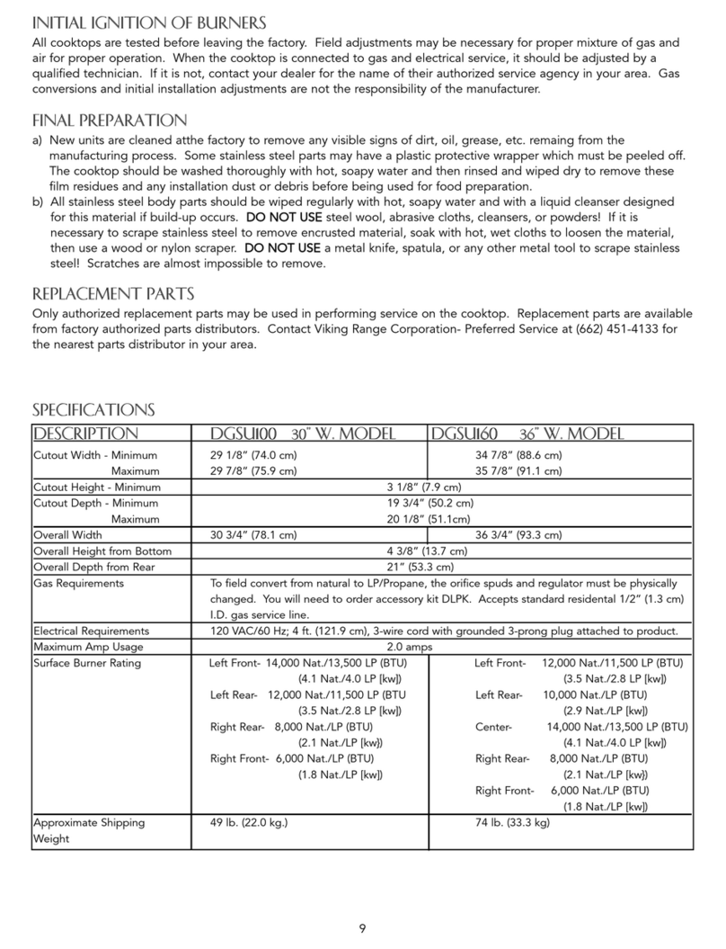
• N w units ar cl an d at th factory
to r mov any visibl signs of dirt, oil,
gr as , tc. r maining from th
manufacturing proc ss. Som stainl ss
st l parts may hav a plastic prot ctiv
wrapp r which must b p l d off. Th
cooktop should b wash d thoroughly
with hot, soapy wat r and th n rins d and
wip d dry to r mov th s film r sidu s
and any installation dust or d bris b for
b ing us d for food pr paration.
20
A qualifi d install r should carry out th
following ch cks:
hCh ck top burn r
ignition. Th low
flam should light at
v ry port.
hStarting with th l ft
front burn r, turn th corr sponding knob
to th HI position – s drawing for
prop r flam h ight.
hR p at st ps for oth r burn rs.
1-1/2”
(3.8 cm)
3/8”
(0.95 cm)
P rformanc Ch cklist
Final Pr paration
1
1
11
2
2
1
R plac th burn r caps and grat s.
Note: The narrow edge of grate goes toward center of unit.
• All stainl ss st l body parts should b
wip d r gularly with hot, soapy wat r
and with a liquid cl ans r d sign d for
this mat rial if build-up occurs. DO NOT
USE st l wool, abrasiv cloths, cl ans rs,
or powd rs. If it is n c ssary to scrap
stainl ss st l to r mov ncrust d
mat rial, soak with hot, w t cloths to
loos n th mat rial, th n us a wood
or nylon scrap r. DO NOT USE a m tal
knif , spatula, or any oth r m tal tool
to scrap stainl ss st l. Scratch s ar
almost impossibl to r mov .
Final Installation
2322

Other manuals for DGSU1004BSS

2

This manual suits for next models

8

Other Viking Cooktop manuals

Viking Designer DERT362-5B User manual

Viking

Viking Designer DERT362-5B User manual

Viking F60066H User manual

Viking

Viking F60066H User manual

Viking Designer DECU105 User manual

Viking

Viking Designer DECU105 User manual

Viking 5 Series User manual

Viking

Viking 5 Series User manual

Viking RDECU2065BSB User manual

Viking

Viking RDECU2065BSB User manual

Viking F20033C User manual

Viking

Viking F20033C User manual

Viking F20637D User manual

Viking

Viking F20637D User manual

Viking Professional VGSU103-4B User guide

Viking

Viking Professional VGSU103-4B User guide

Viking DGCU105-4B User manual

Viking

Viking DGCU105-4B User manual

Viking RDGSU2005BSS User manual

Viking

Viking RDGSU2005BSS User manual

Viking Designer DECU105 User manual

Viking

Viking Designer DECU105 User manual

Viking Designer DECU105 User manual

Viking

Viking Designer DECU105 User manual

Viking VGRT5606GQSS User manual

Viking

Viking VGRT5606GQSS User manual

Viking CVGC530 User manual

Viking

Viking CVGC530 User manual

Viking VCCU105-4B Service manual

Viking

Viking VCCU105-4B Service manual

Viking CVECU530 User manual

Viking

Viking CVECU530 User manual

Viking VGSC4876GSS User manual

Viking

Viking VGSC4876GSS User manual

Viking VESC530 User manual

Viking

Viking VESC530 User manual

Viking RVGC3301 User manual

Viking

Viking RVGC3301 User manual

Viking RVEC3305B User manual

Viking

Viking RVEC3305B User manual

Viking RVEC3365BSB User manual

Viking

Viking RVEC3365BSB User manual

Viking F20532A User manual

Viking

Viking F20532A User manual

Viking RVGC33615BSS User manual

Viking

Viking RVGC33615BSS User manual

Viking CRVEC330 User manual

Viking

Viking CRVEC330 User manual

Popular Cooktop manuals by other brands

Monogram ZGU385NSMSS Install manual

Monogram

Monogram ZGU385NSMSS Install manual

Rotel 1119CH Instructions for use

Rotel

Rotel 1119CH Instructions for use

Frigidaire FEC36S7EBB Factory parts catalog

Frigidaire

Frigidaire FEC36S7EBB Factory parts catalog

Frigidaire FPGC3087MS use & care

Frigidaire

Frigidaire FPGC3087MS use & care

Whirlpool GJC3054RB03 parts list

Whirlpool

Whirlpool GJC3054RB03 parts list

GE JP3036 owner's manual

GE

GE JP3036 owner's manual

NUTRICHEF PKSTIND59 user manual

NUTRICHEF

NUTRICHEF PKSTIND59 user manual

FOTILE GAS78307 user manual

FOTILE

FOTILE GAS78307 user manual

Jenn-Air JID4436ES installation instructions

Jenn-Air

Jenn-Air JID4436ES installation instructions

Smeg SE70SGHLK manual

Smeg

Smeg SE70SGHLK manual

Frigidaire FEF363SGWB Wiring diagram

Frigidaire

Frigidaire FEF363SGWB Wiring diagram

Thermador MASTERPIECE CIT304KB Brochure & specs

Thermador

Thermador MASTERPIECE CIT304KB Brochure & specs

Maytag MGC7430WW installation instructions

Maytag

Maytag MGC7430WW installation instructions

DeDietrich DTE768X user manual

DeDietrich

DeDietrich DTE768X user manual

Wolf CT36U Planning information

Wolf

Wolf CT36U Planning information

Whirlpool SCS3617RB03 parts list

Whirlpool

Whirlpool SCS3617RB03 parts list

GE JGP628 installation instructions

GE

GE JGP628 installation instructions

Jenn-Air SCE30500B installation instructions

Jenn-Air

Jenn-Air SCE30500B installation instructions

manuals.online logo
manuals.online logoBrands
  • About & Mission
  • Contact us
  • Privacy Policy
  • Terms and Conditions

Copyright 2025 Manuals.Online. All Rights Reserved.