manuals.online logo
Brands
  1. Home
  2. •
  3. Brands
  4. •
  5. Viking
  6. •
  7. Irrigation System
  8. •
  9. Viking HORIZON H-3 Instruction manual

Viking HORIZON H-3 Instruction manual

1. PRODUCT NAME
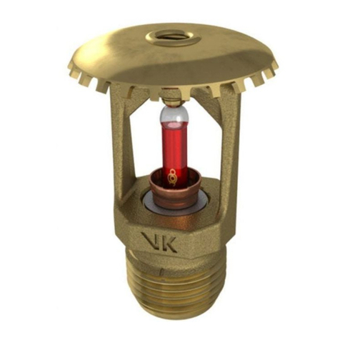
VIKING HORIZON®Model H-3
Residential Flush Pendent Sprinkler
Sprinkler Base Part No: 09458
2. MANUFACTURER
THE VIKING CORPORATION
210 N. Industrial Park Road
Hastings, Michigan 49058 U.S.A.
Telephone: (616) 945-9501
(800) 968-9501
Fax Number: (616) 945-9599
From outside U.S.A.:
Telephone: +1(616) 945-9501
Fax Number: +1(616) 945-9599
3. PRODUCT DESCRIPTION
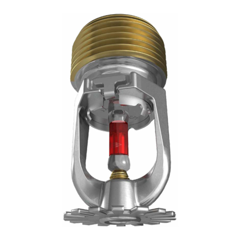
The Viking Horizon®Model H-3 Resi-
dential Sprinkler is a small, flush, high
sensitivity solder link and lever spray
sprinkler. The sprinkler is available in
severalfinisheswithtemperatureratings
to meet varying design requirements.
The sprinkler is listed for use in resi-
dential applications below smooth,
flat horizontal ceilings with spacings
up to 20’ x 20’ and ceilings with
slopes up to and including a 6/12
pitch (26.6o) with spacings up to 18’x
18’. Designed for use with concealed
piping, the unit is mounted flush with the
ceiling, with the fusible link exposed.
The separate decorative ceiling ring al-
lowsforupto1/2"(12,7mm)adjustment.
The two piece design allows the instal-
lation and testing of the sprinklers prior
to the installation of theceiling. Theceil-
ingringcanbe removedandre-installed
allowing access above removable ceil-
ing panels without shutting down the
sprinklersystemandremovingthesprin-
kler.Thedeflectorisheldinsidethebody
until the eutectic metal solder link is
fused. During fire conditions, when the
fusible link reaches its operating tem-
perature, the link, levers and center
cover plate fall away. The deflector is
suspended below the ceiling. Water
flowing through the sprinkler orifice
strikes the deflector forming a uniform
spray pattern over a specific area of
coverage determined by the water sup-
ply pressure at the sprinkler.
4. TECHNICAL DATA
See chart below for listings.
Rated to 175 PSI (1 207 kPa) water
working pressure.
Factory tested pneumatically to 95 PSI
(655 kPa).
See Chart for minimum water supply
requirements and maximum area of
coverage.
Spring: USA Patent No. 4,570,720
Requires a 2" (50,8 mm) diameter hole
in ceiling.
Seechartbelowfortemperatureratings.
Thread Size: Nominal 1/2" (15mm) NPT
K Factor: 3.8 (5,5 metric*)
*Metric K Factor shown is for usewhen pressure
is measured in kPa. When pressure is meas-
ured in BAR, multiply the metric K Factor shown
by 10.0.
Finishes:
Bright Brass, Polished Chrome,
White (Paint), and Navajo White (Paint)
TECHNICAL DATA
R
HORIZON®MODEL H-3
RESIDENTIAL PENDENT
SPRINKLER 3.8 K-FACTOR
Form No. 062395
Sprinkler 145 a
June 9, 1997
Replaces page 145a-d dated October 23, 1996
(Revised Sloped Ceiling Listings)
Maximum Minimum Water Supply Requirements
Coverage 3 Single Sprinkler Two or More UL5,6 C-UL7NYC8--
20’ x 20’ 519 GPM @ 25 PSI 17 GPM @ 20 PSI A1 A1 --
6.1M x 6.1M 72 L/Min @ 173 kPa 65 L/Min @ 138 kPa
18’ x 18’ 516 GPM @ 17.7 PSI 13 GPM @ 11.7 PSI A1 A1 --
5.5M x 5.5M 61 L/Min @ 122 kPa 50 L/Min @ 81 kPa
16’ x 16’ 513 GPM @ 11.7 PSI 11 GPM @ 8.4 PSI A1 A1 --
4.9M x 4.9M 50 L/Min @ 122 kPa 42 L/Min @ 58 kPa
14’ x 14’ 511 GPM @ 8.4 PSI 10 GPM @ 7.0 PSI A1 A1 --
4.3M x 4.3M 42 L/Min @ 58 kPa 38 L/Min @ 48 kPa
12’ x 12’ 510 GPM @ 7.0 PSI 10 GPM @ 7.0 PSI A1 A1 --
3.7M x 3.7M 38 L/Min @ 48 kPa 38 L/Min @ 48 kPa
16’ x 16’ (sloped)616 GPM @ 17.7 PSI 12 GPM @ 9.9 PSI A1 A1 --
4.9M x 4.9M 61 L/Min @ 122 kPa 45 L/Min @ 68 kPa
18’ x 18’ (sloped)620 GPM @ 27.7 PSI 17 GPM @ 20.0 PSI A1 A1 --
5.5M x 5.5M 76 L/Min @ 191 kPa 64 L/Min @ 138 kPa
Deflector Thread Size Nominal Overall Base
Style Size NPT K Factor Length Part Number 2
Inch mm US Metric1Inch mm
Pendent 1/2 15 3.8 5,5 2-5/8 66,7 09458
AREA OF COVERAGE 4APPROVAL KEY
Temperature
Finish
A 1
Nominal
Temperature
Rating
Highest Normal
Ambient Temp.
Allowed
Temperature
Identification
Stamp
Sprinkler
Temperature
Classification
100oF (46oC)
150oF (66oC)
Ordinary
Intermediate On Cover
On Cover
165oF (68oC)
220oF (104oC)
Finishes
1: Polished Chrome, Bright Brass,
White (paint), Navajo White (paint)
Temperature Rating
A: 165oF (74oC)
Footnotes
1Metric K Factor shown is for use use when pressure is measured in kPa. When pressure is measured
in BAR, multiply the metric K Factor shown by 10.0.
2Base part number shown. For complete part number, see Price List.
3For areas of coverage smaller than those shown, use the "Minimum Water Supply Requirement" for the
next larger "Area of Coverage" listed for the sprinkler used. The distance from sprinklers to walls shall
not exceed one half the sprinkler spacing indicated for the "Minimum Water Supply Requirement" used.
4This chart shows the listings and approvals available at the time of printing. Other approvals are in
process. Check with manufacturer for any additional approvals.
5Listing is for Residential occupancies with smooth, flat horizontal ceilings.
6Listing is for all Residential occupancies with ceilings sloped between a 0/12 pitch (0o) and a 6/12
pitch (26.6o). Areas under sloped ceilings must be measured along the slope. Refer to Figure C
Installation Notes, on page 145 d.
7Listed by Underwriters Laboratories, Inc. for use in Canada.
8Acceptance by City of New York Department of Buildings is pending.
OBSOLETE
Materials:
Body: Brass Casting UNS-C84400
Deflector: Copper UNS-C19500
Pin: Stainless Steel UNS-C30300
Body Cap: Brass UNS-C26000
Fusible Element: Beryllium Nickel
Seal: Teflon®Tape
Spring: Nickel Alloy
Screw: Brass UNS-C36000
ACCESSORIES: (order separately)
Sprinkler Wrench: Part No. 08336W/B
Ceiling Ring: 3" (76,2 mm) outside di-
ameter,push-on only. BasePartNo.
09390.
Indicate finish when ordering.
5.AVAILABILITYANDSERVICE
Viking sprinklers are available through a
network of Domestic, Canadian, and In-
ternational Distributors. See the Yellow
Pages of the telephone directory (listed
under “Sprinklers - Automatic - Fire”) or
write to The Viking Corporation.
6. GUARANTEES
For details of warranty, refer to Viking’s
current list price schedule or contact Vi-
king directly.
7. INSTALLATION
WARNING: Viking sprinklers are manu-
factured and tested to meet the rigid
requirements of the approving agency.
The sprinklers are designed to be in-
stalled in accordance with recognized
installation standards. Deviation from
the standards or any alteration to the
sprinkler after it leaves the factory in-
cluding, but not limited to, painting, plat-
ing, coating or modification, may render
the sprinkler inoperative and will auto-
matically nullify the approval and any
guarantee madeby TheVikingCorpora-
tion.
A. Sprinklers are to be installed in ac-
cordance with the latest published
standardsoftheNationalFireProtec-
tion Association, Factory Mutual,
LossPrevention Council,Assemblee
Pleniere, Verband der Sachver-
sicherer or other similar organiza-
tions and also with the provisions of
governmentalcodes,ordinancesand
standards whenever applicable. For
conditionsnotspecificallycoveredby
the Standards, refer to the "Viking
Residential Installation Guide". Fi-
nal approval and acceptance of all
Residential Sprinkler Installations
mustbe obtained from the Author-
ity Having Jurisdiction. Residen-
tial sprinklers are generally consid-
ered special service sprinklers for
one and two family dwellings, mobile
homes and residential portions of
other occupancies where allowed.
The use of residential sprinklers may
belimitedduetooccupancyandhaz-
ard. The minimum flow rate indicated
must be provided at the sprinkler,
therefore, the system piping must be
hydraulically calculated. Refer to the
Authority Having Jurisdiction prior to
installation.
B.Sprinklersmustbehandledwithcare.
Horizon® Model H-3 Residential
Flush sprinklers are provided with a
plastic protective shell which should
remain in place over the sprinkler
body during installation, testing, and
any time the sprinkler is handled or
shipped. The plastic protective shell
must be removed prior to placing the
system in service. See paragraph
"F" below. Prior to installation, sprin-
klers must be stored in a cool, dry
place in their original shipping con-
tainer. Never install sprinklers that
have beendropped, damaged inany
way, or have been exposed to tem-
peratures in excess of maximum am-
bient temperature allowed. Such
sprinklers should be destroyed im-
mediately.
C. Corrosion resistant sprinklers must
beinstalledwhensubjecttocorrosive
atmospheres. Viking Horizon®sprin-
klers are not intended for use in cor-
rosive environments.
D. Use care when locating sprinklers
near fixtures that can generate heat.
Do not install sprinklers where they
will be exposed to temperatures that
exceed the maximum recommended
ambient temperature for the tem-
perature rating used.
E. Sprinklers must be protected from
mechanical damage. Wet pipe sys-
temsmustbeprovidedwithadequate
heat.
F. The sprinklers must be installed after
the piping is in place to prevent me-
chanical damage. Before installing,
make sure the appropriate model,
style, orifice size, and temperature
rating with the desired response
characteristic is used. Install the
sprinklers according to the following
steps:
Step 1: Install all piping and cut the
sprinkler drop nipple to position
the 1/2" (15mm) NPT outlet of the
reducing coupling at the desired
elevation. The drop nipple must
beperpendiculartotheceilingand
centered in a 2" (50mm) diame-
ter opening in the ceiling.
Step2: Withthesprinklerintheplas-
tic protective shell, apply a small
amount of pipe joint compound or
tape to the external threads ofthe
sprinkler only.
Step 3: Use only the special wrench*
designed for installing Viking Ho-
rizonSprinklers. With the sprinkler
in the plastic protective shell,
place the unit into the wrench.
* Sprinkler Wrench PN 08336W/B is required.
Previous Viking Horizon Flush Sprinkler
Wrenches appear similar, but were manufac-
tured with a larger outside diameter.
A 1/2" ratchet is required (not available from
Viking).
Step 4: Turn the unit clockwise to
thread the sprinkler into the 1/2"
(15mm) NPT outlet of the cou-
pling. DONOTusethefusiblelink
to start or thread the sprinkler into
a fitting.
G. After installation, the entire system
must be tested in accordance with
Figure A
TECHNICAL DATA HORIZON®MODEL H-3
RESIDENTIAL PENDENT
SPRINKLER 3.8 K-FACTOR
June 9, 1997
Sprinkler 145 b
Form No. 062395
R
** A 1/2" ratchet is
required. (Not
available from Viking).
2" (50mm)
diameter
hole required.
Sprinkler
Wrench**
Part No.
08336W/B
VIKING
HORIZON®
Model H-3
Residential
Flush Pendent
Sprinkler
Protective
Cap
OBSOLETE
the recognized installation stand-
ards. The test is applied after the
sprinkler installation to ensure no
damagehasoccurredtothesprinkler
during shipping and installation, and
to make surethe unit has beenprop-
erly tightened. If a thread leak should
occur, normally the unit must be re-
moved, new pipe joint compound or
tape applied, and reinstalled. This is
duetothefactthatwhenthejointseal
is damaged, the sealing compound
or tape is washed out of the joint.
H. After testing, repairing all leaks, and
installationandpaintingoftheceiling,
the ceiling ring can be installed.
1. Remove the plastic protective
cap. (It is recommended to retain
a protective shell in the spare
sprinkler cabinet. The internal di-
ameter of the special Installation
wrench is designed for use with
the sprinkler contained in a pro-
tective shell.)
2. Push on the ceiling ring until the
ring touches the ceiling. Ceiling
rings should be installed to en-
sure proper operation of the
sprinkler.
Note: The maximum vertical adjustment
is 1/2" (12,7 mm). DO NOT MODIFY
THEUNIT. Ifnecessaryre-cutthe sprin-
klerdropnippleasrequired. NEVERuse
glueorcaulkingmaterialtofastenorseal
the ceiling ring to the ceiling. Such pro-
cedure may result in the sprinkler failing
to operate properly.
I. DISASSEMBLY: The ceiling ring can
be removed and reinstalled (without
removing the sprinkler) to allow ac-
cess above theceilingor to replace if
necessary. If it is necessary to re-
movetheentire unit,thesystemmust
be removed from service. See Main-
tenance instructions and follow all
warnings and instructions.
8. MAINTENANCE
NOTICE: The owner is responsible for
maintaining the fire protection system
and devices in proper operating condi-
tion. For minimum maintenance and in-
spection requirements, refer to the Na-
tional Fire Protection Association Pam-
phlet that describes the care and main-
tenance of sprinkler systems. In addi-
tion, the “Authority Having Jurisdiction”
may have additional maintenance, test-
ing and inspection requirements which
must be followed.
A. The sprinklers must be inspected on
a regular basis for corrosion, me-
chanical damage, obstructions,
paint, etc. The frequency of the in-
spections may vary due to corrosive
atmospheres, water supplies andac-
tivity around the device.
B. Sprinklers that have been field
painted or mechanically damaged
must be replaced immediately.
Sprinklersshowingsignsofcorrosion
shall be tested and/or replaced im-
mediately as required. Residential
sprinklers that are 20 years old shall
be tested and/or replaced as re-
quired. Sprinklers that have oper-
ated cannot be reassembled or re-
used, but must be replaced. When
replacing sprinklers, use only new
sprinklers.
C. The sprinkler discharge pattern is
critical for proper fire protection;
therefore nothing should be hung
from, attached to, or otherwise ob-
struct the discharge pattern. All ob-
structions must be immediately re-
moved or, if necessary, additional
sprinklers installed.
D. When replacing existing sprinklers,
the system must be removed from
service. Refer to the appropriate
system description and/or valve in-
structions. Prior to removing the sys-
temfromservice,notifyallAuthorities
Having Jurisdiction. Consideration
should be given to employment of a
fire patrol in the affected area.
1. Remove the system from service,
draining all water and relieving all
pressure on the piping.
2. Remove the ceiling ring. "Push-
on" ceiling rings are removed by
pulling the ring downward.
3. Place a plastic protective shell
(from the spare sprinkler cabinet)
over the sprinkler to be removed.
The internal diameter of the spe-
cial Horizon sprinkler installation
wrench is designed for use with
the sprinkler contained in the
shell.
4. Using the special sprinkler wrench,
turn the unit counterclockwise to
remove the old sprinkler from the
piping in which it is installed.
5. Install the newunit. Care must be
taken to replace the sprinkler
with the proper model, style,
orifice size, temperature rating
and response characteristics,
with approvals and listings
matchingtheexistingsprinkler.
A fully stocked spare sprinkler
cabinetshouldbeprovidedforthis
purpose
6. Replace the ceiling ring.
7. Place the system back in service
and secure all valves. Check and
repair all leaks.
F. Sprinkler systems that have been
subjected to a fire must be returned
to service as soon as possible. The
entire system must be inspected for
damage and repaired or replaced as
necessary. Sprinklers that have
been exposed to corrosive products
of combustion or high ambient tem-
peratures, but have not operated,
should be replaced. Refer to the
AuthorityHavingJurisdictionformini-
mum replacement requirements.
Figure B
TECHNICAL DATA HORIZON®MODEL H-3
RESIDENTIAL PENDENT
SPRINKLER 3.8 K-FACTOR
Sprinkler 145 c
June 9, 1997
Form No. 062395
R
OBSOLETE
Figure C Installation Guidelines
Figure D Installation Guidelines - Lofts
Notes:
1. Actual installations may require multiple sprinklers. A single sprinkler installation has been
shown for clarity.
2. For "cathedral" ceiling applications, install sprinklers in a symmetrical mirror-image of Figure C.
An 8" (minimum) beam or lintel is required at the peak. Refer to Figure D below.
3. For areas up to 18’ x 18’, with slopes between a 0/12 pitch (0o) and a 6/12 pitch (26.6o), the
"Minimum Water Supply Requirements" for the next largest "sloped" installation must be used.
Refer to Approval Chart on page 145 a.
Form No. 062395
Replaces page 145a-d dated October 23, 1996
(Revised Sloped Ceiling Listings)
Sprinkler 145 d June 9, 1997
TECHNICAL DATA HORIZON®MODEL H-3
RESIDENTIAL PENDENT
SPRINKLER 3.8 K-FACTOR
R
Listed Areas of Coverage
correspond to areas measured
along ceiling slope.
(for sloped ceiling installations,
actual floor coverage will be
less than listed area).
Refer to chart on
Page 145 a
for listed areas
of coverage.
Maximum
ceiling
slope = 6/12.
(26.6o).
Minimum 8" lintel for loft / upper
level (cathedral) applications.
Maximum 6/12
pitch (26.6o).
Refer to Approval
Chart
on Page 145 a.
OBSOLETE

Other Viking Irrigation System manuals

Viking VK4921 Instruction manual

Viking

Viking VK4921 Instruction manual

Viking MICROFAST VK327 User manual

Viking

Viking MICROFAST VK327 User manual

Viking VK2021 Instruction manual

Viking

Viking VK2021 Instruction manual

Viking VK3502 Instruction manual

Viking

Viking VK3502 Instruction manual

Viking MICROFAST VK3311 Instruction manual

Viking

Viking MICROFAST VK3311 Instruction manual

Viking FREEDOM VK460 Instruction manual

Viking

Viking FREEDOM VK460 Instruction manual

Viking SIN VK500 Instruction manual

Viking

Viking SIN VK500 Instruction manual

Viking 10224 Instruction manual

Viking

Viking 10224 Instruction manual

Viking 14073AC Instruction manual

Viking

Viking 14073AC Instruction manual

Viking MICROFAST VK332 Instruction manual

Viking

Viking MICROFAST VK332 Instruction manual

Viking VK531 Instruction manual

Viking

Viking VK531 Instruction manual

Viking MICROFAST VK307 Instruction manual

Viking

Viking MICROFAST VK307 Instruction manual

Viking VK4651 Instruction manual

Viking

Viking VK4651 Instruction manual

Viking MICROFAST VK3271 Instruction manual

Viking

Viking MICROFAST VK3271 Instruction manual

Viking FREEDOM VK472 Instruction manual

Viking

Viking FREEDOM VK472 Instruction manual

Viking VK512 K25.2 Instruction manual

Viking

Viking VK512 K25.2 Instruction manual

Viking VK3542 Instruction manual

Viking

Viking VK3542 Instruction manual

Viking HORIZON H-3 Instruction manual

Viking

Viking HORIZON H-3 Instruction manual

Viking MICROFAST VK345 Instruction manual

Viking

Viking MICROFAST VK345 Instruction manual

Viking MICROFAST VK311 Instruction manual

Viking

Viking MICROFAST VK311 Instruction manual

Viking VK1001 Instruction manual

Viking

Viking VK1001 Instruction manual

Viking MICROFAST VK303 Instruction manual

Viking

Viking MICROFAST VK303 Instruction manual

Viking MIRAGE VK632 Instruction manual

Viking

Viking MIRAGE VK632 Instruction manual

Viking VK800 Instruction manual

Viking

Viking VK800 Instruction manual

Popular Irrigation System manuals by other brands

Johnson Controls tyco RAVEN manual

Johnson Controls

Johnson Controls tyco RAVEN manual

Autopot SmartPot 9 XL Set-up guidelines

Autopot

Autopot SmartPot 9 XL Set-up guidelines

hillvert HT-COSTIGAN-30X12S01 user manual

hillvert

hillvert HT-COSTIGAN-30X12S01 user manual

Tyco RFII-C Series manual

Tyco

Tyco RFII-C Series manual

Reliable F156 Series manual

Reliable

Reliable F156 Series manual

Johnson Controls tyco TY-FRL Series manual

Johnson Controls

Johnson Controls tyco TY-FRL Series manual

Tyco RAPID RESPONSE Series manual

Tyco

Tyco RAPID RESPONSE Series manual

Eden 94804-EDAMZ quick start guide

Eden

Eden 94804-EDAMZ quick start guide

GEM G100 manual

GEM

GEM G100 manual

Hunter Institutional Series manual

Hunter

Hunter Institutional Series manual

Tyco Fire Product Star E instruction manual

Tyco Fire Product

Tyco Fire Product Star E instruction manual

CENTRAL ELO-231 manual

CENTRAL

CENTRAL ELO-231 manual

Tyco AquaMist AM4 quick start guide

Tyco

Tyco AquaMist AM4 quick start guide

Tyco Fire Product CENTRAL Attic BB1-17/32 instruction manual

Tyco Fire Product

Tyco Fire Product CENTRAL Attic BB1-17/32 instruction manual

Tyco Fire Product Gem F890 instruction manual

Tyco Fire Product

Tyco Fire Product Gem F890 instruction manual

Orbit Voyager II user manual

Orbit

Orbit Voyager II user manual

Tyco Fire Product Gem RFII Series instruction manual

Tyco Fire Product

Tyco Fire Product Gem RFII Series instruction manual

Tyco Fire Product CENTRAL EC-25 instruction manual

Tyco Fire Product

Tyco Fire Product CENTRAL EC-25 instruction manual

manuals.online logo
manuals.online logoBrands
  • About & Mission
  • Contact us
  • Privacy Policy
  • Terms and Conditions

Copyright 2025 Manuals.Online. All Rights Reserved.