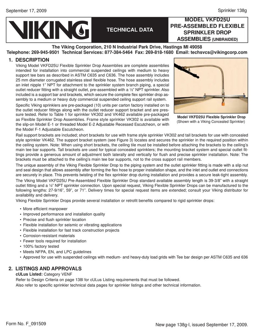
MICROFAST®QUICK
RESPONSE FUSIBLE
ELEMENT HSW SPRINKLER
VK307 (K5.6)
TECHNICAL DATA
Page 4 of 7
Form No. F_062714 20.06.04 Rev 20.1
The Viking Corporation, 210 N Industrial Park Drive, Hastings MI 49058
T
elephone:
269-945-9501
T
echnical
Services:
877-384-5464
Fax:
269-818-1680
Email:
[email protected]Visit the Viking website for the latest edition of this technical data page www.vikinggroupinc.com.
DESIGN CRITERIA - UL
(Also refer to Approval Chart 1 above.)
cULus Listing Requirements:
Quick Response Horizontal Sprinkler VK307 is cULus Listed as indicated in the Approval Chart for installation in accordance with the latest edition of
NFPA 13 for sidewall standard spray sprinklers.
• Sprinkler VK307 is limited to Light Hazard occupancies only.
• Locate Sprinkler VK307 with the deflector 6” to 12“ (152 mm to 305 mm) below the ceiling.
• Protection areas and maximum spacing shall be in accordance with the tables provided in NFPA 13.
• Minimum spacing allowed is 6 ft. (1.8 m).
• Align the top of the deflector parallel with the ceiling.
• Locate no less than 4” (102 mm) from end walls.
• Maximum distance from end walls shall be no more than one-half of the allowable distance between sprinklers. The distance shall be measured
perpendicular to the wall.
• The sprinkler installation and obstruction rules contained in NFPA 13 for sidewall standard spray sprinklers must be followed.
IMPORTANT: Always refer to Bulletin Form No. F_091699 - Care and Handling of Sprinklers. Also refer to Form No. F_080614
for general care, installation, and maintenance information. Viking sprinklers are to be installed in accordance with the latest
edition of Viking technical data, the appropriate standards of NFPA, LPCB, APSAD, VdS or other similar organizations, and
also with the provisions of governmental codes, ordinances, and standards, whenever applicable.
Approval Chart 1 (UL)
Quick Response Fusible Element Horizontal Sidewall Sprinkler VK307
Maximum 175 PSI WWP
For Light Hazard Occupancies Only.
Base Part
Number1SIN Maximum
Pressure
Thread Size Nominal K-Factor Overall Length Listings and Approvals3
(Refer also to Design Criteria below.)
NPT BSPT U.S. metric2Inches mm cULus4
Deflectors must be located 4” to 6” (102 mm to 152 mm) below the ceiling.
13947 VK307 175 psi 1/2” 15 mm 5.6 80.6 2-1/2 64 A1Y, B1X, A2Y, B2W
Deflectors must be located 6” to 12” (152 mm to 305 mm) below the ceiling.
13947 VK307 175 psi 1/2” 15 mm 5.6 80.6 2-1/2 64 A1Y, A2Y
NOTICE - Product Below - Limited Availability (Contact Local Viking Office)
Deflectors must be located 4” to 6” (102 mm to 152 mm) below the ceiling.
13948 VK307 175 psi 1/2” 15 mm 5.6 80.6 2-1/2 64 A1Y, B1X
Deflectors must be located 6” to 12” (152 mm to 305 mm) below the ceiling.
13948 VK307 175 psi 1/2” 15 mm 5.6 80.6 2-1/2 64 A1Y
Approved Temperature Ratings
A - 165 °F (74 °C), 205 °F (96 °C), 280
°F (138 °C)
B - 165 °F (74 °C) and 205 °F (96 °C)
Approved Finishes
1 - Brass, Chrome, White Polyester5, and Black
Polyester5
2 - ENT6
Approved Escutcheons
W -Installed with standard surface-mounted
escutcheons or Recessed with the Viking
Micromatic Model E-1
X -Installed with standard surface-mounted
escutcheons or recessed with the Viking
Micromatic®Model E-1 or E-2 Recessed
Escutcheon
Y -Installed with standard surface-mounted
escutcheons only
Footnotes
1 Base part number shown. For complete part number, refer to Viking’s current price schedule.
2 Metric K-factor measurement shown is when pressure is measured in Bar. When pressure is measured in kPa, divide the metric K-factor shown by 10.0.
3 This table shows the listings and approvals available at the time of printing. Other approvals may be in process.
4 Listed by Underwriters Laboratories Inc. for use in the U.S. and Canada.
5 Other colors are available on request with the same Listings and Approvals as the standard colors.
6 cULus Listed as corrosion resistant.
