manuals.online logo
Brands
  1. Home
  2. •
  3. Brands
  4. •
  5. Viking
  6. •
  7. Irrigation System
  8. •
  9. Viking Microfast M-7 Instruction manual

Viking Microfast M-7 Instruction manual

1. PRODUCT NAME
Viking Microfast® Model M-7 Low-Flow
Residential Horizontal Sidewall Sprinkler
•Base Part Number 10210
•Available since 1997.
2. MANUFACTURER
The Viking Corporation
210 N. Industrial Park Road
Hastings, Michigan 49058 USA
Telephone:(616) 945-9501
(877) 384-5464
Fax:(616) 945-9599
e-mail: [email protected]m
3. PRODUCT DESCRIPTION
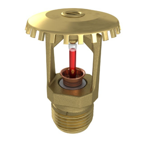
The Viking Microfast ® Model M-7,
Low-Flow Residential Horizontal Side-
wall Sprinkler, is a small,
high-sensitivity, glass-bulb residential
spray sprinkler. The sprinkler is avail-
able in several finishes, with tempera-
ture ratings to meet varying design re-
quirements. The orifice design, with a
K-factor of 3.7, allows efficient use of
availablewatersuppliesforthehydrauli-
cally designed fire-protection system.
The small, rugged 3 mm glass bulb and
special deflector combine speed of op-
eration and area of coverage to meet
residential sprinkler standards, while
being aesthetically pleasing.
The sprinkler is listed for use below
smooth, flat, horizontal ceilings only.
Duringfireconditions,theheat-sensitive
liquidintheglassbulbexpands,causing
the glass to shatter, releasing the
pip-cap and sealing spring assembly.
The water flowing through the sprinkler
orifice strikes the sprinkler deflector,
forming a uniform spray pattern to extin-
guish or control the fire.
4. TECHNICAL DATA
LISTINGS AND APPROVALS
Refer toTable 1 on page 151 c.
See chart for minimum water supply re-
quirements and maximum areas of
coverage.
Glass-bulb fluid temperature rated to
-65 °F (-55 °C).
Ratedto175psi(1207kPa)waterwork-
ing pressure.
Factory tested hydrostatically to 500 psi
(3 448 kPa).
Spring: USA Patent No. 4,167,974
Bulb: USA Patent No. 4,796,710
Testing: USA Patent No. 4,831,870
Thread Size: ½" (15 mm) NPT
Orifice Size: Nominal 3/8" (10 mm)
K-factor: 3.7 US (5,3 metric*)
* Metric K-factor shown is for use when pressure is
measured in kPa. When pressure is measured in
BAR, multiply the metric K-factor shown by 10.0.
SPRINKLER MATERIALS
Frame: Brass Castings UNS-C84400
Deflector: Copper UNS-C19500
Bulb: Glass, nominal 3 mm diameter
Seal: Teflon®Tape
Spring: Nickel Alloy
Screw: Brass UNS-C36000
Pip Cap: Copper UNS-C11000 and
Stainless Steel UNS-S30400
ACCESSORIES
Sprinkler Wrenches:
•Standard: Part No. 05000CW/B
Available since 1982.
•Recessed: Part No. 07398W
Available since 1990.
Refer to the “SPRINKLER ACCES-
SORIES” section of the Viking Engi-
neering and Design Databook for tech-
nical data on escutcheons.
5. AVAILABILITY AND SERVICE
Vikingsprinklers are availablethrough a
network of domestic, Canadian, and in-
ternational distributors. See the Yellow
Pagesofthetelephonedirectoryforalo-
cal distributor (listed under “Sprin-
klers-Automatic-Fire”)orcontactViking.
Viking Technical Data may be found on
The Viking Corporation’s Web site at
http://www.vikingcorp.com.
The Web site may include a more recent
edition of this technical data page.
6. GUARANTEES
For details of warranty, refer to Viking’s
currentpricescheduleorcontactTheVi-
king Corporation directly.
7. INSTALLATION
WARNING:Viking sprinklers are manu-
factured and tested to meet the rigid re-
quirements of approving agencies. The
sprinklersaredesignedto be installedin
accordance with recognized installation
standards.Deviationfromthestandards
or any alteration to the sprinkler after it
leaves the factory including, but not lim-
ited to: painting, plating, coating, or
modification, may render the sprinkler
inoperative and will automatically nullify
the approval and any guarantee made
by The Viking Corporation.
A.Sprinklersaretobeinstalledinaccor-
dance with the latest published stan-
dards of the National Fire Protection
Association, Factory Mutual, Loss
Prevention Council, Assemblee
Pleniere, Verband der
Sachversicherer or other similar or-
ganizations,and alsowith provisions
of governmental codes, ordinances,
and standards whenever applicable.
For conditions not specifically cov-
ered by the Standards, refer to the
“Viking Residential Installation
Guide”. Final approval and accep-
tance of all residential sprinkler in-
stallationsmust be obtainedfrom the
Authority Having Jurisdiction. Resi-
dential sprinklers are special service
sprinklers for use in one- and
two-family dwellings, mobile homes,
and residential portions of other oc-
cupancies, where allowed. The use
of residential horizontal sidewall
sprinklers may be limited due to oc-
cupancy and hazard. The minimum
flow rate indicated for a listed area of
coverage must be provided at the
sprinkler. Therefore, the system
mustbe hydraulically calculated.Re-
fer to the Authority Having Jurisdic-
tion prior to installation.
B.Sprinklersmustbehandledwithcare.
They must be stored in a cool, dry
place in their original container.
Never install sprinklers that have
been dropped or damaged in any
way. Never install any glass-bulb
sprinkler if the bulb is cracked or if
there is a loss of liquid from the bulb.
If a glass bulb lacks the appropriate
amountoffluid, itshouldbe setaside
and returned to Viking (or an autho-
rized Viking distributor) for analysis
assoonaspossible.Ifthesprinkleris
not returned to Viking, it should be
destroyed immediately. Never install
sprinklers which have been exposed
to temperatures in excess of maxi-
mum ambient temperature allowed.
Such sprinklers should be destroyed
immediately.
C. Corrosion-resistant sprinklers must
be installed when subject to corro-
sive atmospheres. Viking Microfast ®
ResidentialHorizontalSprinklersare
not intended for use in corrosive
environments.
D. Use care when locating sprinklers
near fixtures that can generate heat.
Sprinkler 151 a
May 27, 1999
Form No. F_082297Replaces sprinkler page 151 a-d, dated July 16, 1998
(revised pip-cap materials).
Units of measure in parentheses may be approximations.
TECHNICAL DATAMicrofast ®MODEL M-7
LOW-FLOW RESIDENTIAL
HORIZONTAL SIDEWALL
SPRINKLER
OBSOLETE
Do not install sprinklers where they
will be exposed to temperatures that
exceed the maximum recommended
ambient temperature for the temper-
ature rating used.
E. Sprinklers must be protected from
mechanical damage. Adequate heat
must be provided when sprinklers
are installed on wet-pipe systems.
F. The Microfast®Model M-7 Low-Flow
Residential Horizontal Sidewall
Sprinkler must be installed after the
pipingisin placetoprevent mechani-
cal damage, and must be installed
only below smooth, flat, horizontal
ceilings. Refer to approval chart on
page 151 c for allowable deflector
distance below the ceiling, and note
minimumwatersupplyrequirements.
The top of the horizontal sidewall de-
flector must be aligned parallel to the
ceiling.
Before installation, be sure to have
the appropriate sprinkler model and
style, with the correct orifice size,
temperature rating, and response
characteristics.
1. Install escutcheon (if used), which
is designed to thread onto the ex-
ternal threads of the sprinkler.
Refer to the “Sprinkler Acces-
sories” section of the V iking Engi-
neering and Design Databook for
technical data on approved es-
cutcheonsandotheraccessories.
2. Apply a small amount of pipe-joint
compound or tape to the external
threads of the sprinkler only, tak-
ing care not to allow a build-up of
compound in the sprinkler inlet.
3. Care must be taken when install-
ing sprinklers on CPVC and cop-
per piping systems. Never install
the sprinkler into the reducing fit-
ting before attaching the reducing
fitting to the piping.
Sprinklers must be installed on
CPVC systems after the reducing
fitting has been installed and the
primer and/or cement manufac-
turer’s recommended curing time
has elapsed.
When installing sprinklers on cop-
per piping systems, take care to
brush the inside of the sprinkler
supply piping and reducing fitting
toensurethatnofluxaccumulates
inthe sprinklerorifice. Excess flux
can cause corrosion and may im-
pair the ability of the sprinkler to
operate properly.
4. Install the sprinkler on the piping
usingthe special sprinklerwrench
only, taking care not to over-
tighten or damage the sprinkler
operating parts. DO NOT use the
sprinkler deflector to start or
thread the sprinkler into a fitting.
G. After installation, the entire sprinkler
systemmustbetestedinaccordance
with the recognized installation stan-
dards. The test is applied after sprin-
kler installation to ensure that no
damagehasoccurredtothesprinkler
during shipment and installation, and
to make sure the unit has been prop-
erlytightened.Ifathreadleakoccurs,
normally the unit must be removed,
new pipe-joint compound or tape ap-
plied, and then reinstalled. This is
duetothefactthatwhenthejointseal
leaks, the sealing compound is
washed out of the joint.
8. MAINTENANCE
NOTICE: The owner is responsible for
maintaining the fire-protection system
and devices in proper operating condi-
tion. For minimum maintenance and in-
spection requirements, refer to the Na-
tional Fire Protection Association’s
pamphlet that describes care and main-
tenance of sprinkler systems. In addi-
tion, the Authority Having Jurisdiction
may have additional maintenance, test-
ing, and inspection requirements that
must be followed.
A.Thesprinklersmustbeinspectedona
regular basis for signs of corrosion,
mechanical damage, obstructions,
paint, etc. The frequency of the in-
spections may vary due to corrosive
atmospheres, water supplies, and
activity around the device.
B. Sprinklers that have been field
painted, caulked, or mechanically
damaged must be replaced immedi-
ately. Sprinklers showing signs of
corrosion shall be tested and/or re-
placed immediately as required.
Microfast® Residential Sprinklers
that are 20 years old shall be tested
and/or replaced immediately as re-
quired. Never attempt to repair or re-
assemble a sprinkler. Sprinklers that
have operated cannot be reassem-
bled or re-used, but must be re-
placed. When replacing sprinklers,
useonlynewsprinklerswithidentical
performance characteristics.
C. The sprinkler discharge pattern is
critical for proper fire protection.
Nothing should be hung from, at-
tached to, or otherwise obstruct the
discharge pattern of the sprinkler. All
obstructionsmustbeimmediatelyre-
moved or, if necessary, additional
sprinklers installed.
D. When replacing existing sprinklers,
the system must be removed from
service.Refertotheappropriate sys-
tem description and/or valve instruc-
tions. Prior to removing the system
from service, notify all Authorities
Having Jurisdiction. Consideration
should be given to employment of a
fire patrol in the effected area.
1. Remove the system from service,
drain all water, and relieve all
pressure on the piping.
2. Using the special sprinkler
wrench, remove the old sprinkler
and install the new unit. Care
must be taken to ensure that the
replacement sprinkler is the
proper model and style, with the
correct orifice size, temperature
rating, and response characteris-
tics.A fully stockedsprinkler cabi-
net should be provided for this
purpose.
3. Place the system back in service
and secure all valves. Check and
repair all leaks.
E. Sprinkler systems that have been
subjected to a fire must be returned
to service as soon as possible. The
entire system must be inspected for
damage,andrepairedorreplacedas
necessary. Sprinklers that have
been exposed to corrosive products
of combustion or high ambient tem-
peratures, but have not operated,
should be replaced. Refer to the Au-
thority Having Jurisdiction for mini-
mum replacement requirements.
May 27, 1999Sprinkler 151 b
TECHNICAL DATAMicrofast ®MODEL M-7
LOW-FLOW RESIDENTIAL
HORIZONTAL SIDEWALL
SPRINKLER
OBSOLETE
Sprinkler 151 c
May 27, 1999
TECHNICAL DATAMicrofast ®MODEL M-7
LOW-FLOW RESIDENTIAL
HORIZONTAL SIDEWALL
SPRINKLER
Note: Units of measure in parentheses may be approximations.
Sprinkler
Temperature
Classification
Nominal Sprinkler
Temperature Rating
(Fusing Point)
Ceiling Temperature at Sprinkler
Maximum Ambient
Temperature Allowed 1Maximum Recommended
Ambient Temperature 2Bulb
Color
Ordinary155 °F (68 °C)135 °F (46 °C)100 °F (38 °C)Red
Intermediate175 °F (79 °C)155 °F (68 °C)150 °F (65 °C)Yellow
Sprinkler Finishes: Brass, Bright Brass, Chrome-Enloy ®(patents pending), White (paint), and Navajo White (paint)
1Based on National Fire Prevention and Control Administration, Contract No. 7-34860.
2Based on NFPA-13. Other limits may apply depending on fire loading, sprinkler location, an d other requirements of the Authority Having
Jurisdiction. Refer to specific installation standards.
Deflector StyleNPT Thread SizeNominal OrificeNominal K-FactorOverall LengthBase Part
Number 3
InchmmInchmmInchmm8Inchmm
Horizontal Sidewall½153/8103.75,33.076,210210
Approval Chart
Microfast ®Model M-7
Low-Flow Residential Horizontal Sidewall Sprinkler
Sprinkler Installed 4" to 6" (100 mm to 152,4 mm) Below the Ceiling
Maximum Areas
of Coverage 6
Width x Length
Minimum Water Supply Requirements 6Listings 4
Single SprinklerTwo or More SprinklersUL 5C-UL 5,7
12' x 12'
(3,7 m x 3,7 m)13.0 gpm @ 12.3 psi
(49,2 L/min @ 86,2 kPa12.0 gpm @ 10.5 psi
(45,4 L/min @ 73,4 kPaA1XA1X
14' x 14'
(4,3 m x 4,3 m)15.0 gpm @ 16.4 psi
(56,8 L/min @ 114,9 kPa14.0 gpm @ 14.3 psi
(53,0 L/min @ 100,0 kPaA1XA1X
16' x 16'
(4,9 m x 4,9 m)16.0 gpm @ 18.7 psi
(60,6 L/min @ 130,7 kPa15.0 gpm @ 16.4 psi
(56,8 L/min @ 114,9 kPaA1XA1X
Sprinkler Installed 6" to 12" (152 mm to 305 mm) Below the Ceiling
12' x 12'
(3,7 m x 3,7 m)14.0 gpm @ 14.3 psi
(53,0 L/min @ 100,0 kPa13.0 gpm @ 12.3 psi
(49,2 L/min @ 73,4 kPaA1XA1X
14' x 14'
(4,3 m x 4,3 m)17.0 gpm @ 21.1 psi
(64,4 L/min @ 147,6 kPa15.5 gpm @ 17.5 psi
(58,7 L/min @ 122,7 kPaA1XA1X
16' x 16'
(4,9 m x 4,9 m)18.0 gpm @ 23.7 psi
(68,1 L/min @ 165,1 kPa17.0 gpm @ 21.1 psi
(64,4 L/min @ 147,6 kPaA1XA1X
Approved
Temperatures
A - 155 °F (68 °C) and
175 °F (79 °C)
Approved Finishes
1 - Brass, Bright Brass, Chrome- Enloy ®,
White (paint), and Navajo White (paint)
Approved Escutcheons
X - Standard surface-mounted escutcheons or Microfast ®Model F-1
Adjustable Escutcheon 9, orrecessed with the Micromatic ® Model
E-1 Adjustable Recessed Escutcheon 10
Footnotes
3 Base part number shown. For complete part number, see price list.
4This chart shows the listings and approvals available at the time of printing. Other approvals are in process. Check with the manufacturer
for any additional approvals.
5Listing is for residential occupancies with smooth, flat, horizontal ceilings.
6For areas of coverage smaller than shown, use the "Minimum Water Supply Requirement" for the next larger area listed. Flows and pres-
sures listed are per sprinkler.
7Listed by Underwriters Laboratories Inc. for use in Canada.
8Metric K-factor shown is for use when pressure is measured in kPa. When pressure is measured in BAR, multiply the metric K-factor
shown by 10.0.
9The Microfast ®Model F-1 Adjustable Escutcheon is considered a surface-mounted escutcheon because it do es not allow the fusible ele-
ment of the sprinkler to be recessed behind the face of the wall or ceiling.
10 When installing the Microfast ®Model M-7 Low-Flow Residential Horizontal Sidewall Sprinkler with the Micromatic ®Model E-1 Adjustable
Recessed Escutcheon, the allowable sprinkler recess is ½" (15 mm). Refer to Figure 1 on pag e 151 d.
Table 1
KEY
Temperature
Finish
A1XEscutcheon (if applicable)
OBSOLETE
Replaces sprinkler page 151 a-d, dated July 16, 1998
(revised pip-cap materials).FormNo.F_082297
May 27, 1999
Sprinkler 151 d
TECHNICAL DATAMicrofast ®MODEL M-7
LOW-FLOW RESIDENTIAL
HORIZONTAL SIDEWALL
SPRINKLER
Microfast ®Model M-7
Low-Flow Residential Horizontal Sidewall Sprinkler
Installed with 1/8" (3,2 mm) Deep
Surface-Mounted Escutcheon
Microfast ®Model M-7
Low-Flow Residential Horizontal Sidewall Sprinkler
Installed with 1" (25,4 mm) Deep
Surface-Mounted Escutcheon
Microfast ®Model M-7
Low-Flow Residential Horizontal Sidewall Sprinkler
Installed with Viking Micromatic® Model E-1 Adjustable Recessed Escutcheon
Figure 1
Installation of Microfast®Model M-7
Low-Flow Residential Horizontal Sidewall Sprinkler
OBSOLETE

Other Viking Irrigation System manuals

Viking VK204 Instruction manual

Viking

Viking VK204 Instruction manual

Viking VK108 Instruction manual

Viking

Viking VK108 Instruction manual

Viking 10224 Instruction manual

Viking

Viking 10224 Instruction manual

Viking HQR-2 Instruction manual

Viking

Viking HQR-2 Instruction manual

Viking QR1 Operating manual

Viking

Viking QR1 Operating manual

Viking GB 460 User manual

Viking

Viking GB 460 User manual

Viking VK638-D Instruction manual

Viking

Viking VK638-D Instruction manual

Viking MICROFAST VK311 Instruction manual

Viking

Viking MICROFAST VK311 Instruction manual

Viking VK506 Instruction manual

Viking

Viking VK506 Instruction manual

Viking MicrofastHP VK340 Instruction manual

Viking

Viking MicrofastHP VK340 Instruction manual

Viking VK950 User manual

Viking

Viking VK950 User manual

Viking VK1001 Instruction manual

Viking

Viking VK1001 Instruction manual

Viking FREEDOM VK484 Instruction manual

Viking

Viking FREEDOM VK484 Instruction manual

Viking MICROFAST VK332 Instruction manual

Viking

Viking MICROFAST VK332 Instruction manual

Viking VK5141 Instruction manual

Viking

Viking VK5141 Instruction manual

Viking MICROMATIC VK202 Instruction manual

Viking

Viking MICROMATIC VK202 Instruction manual

Viking VK3501 Instruction manual

Viking

Viking VK3501 Instruction manual

Viking Microfast M-6 Instruction manual

Viking

Viking Microfast M-6 Instruction manual

Viking FREEDOM VK495 Instruction manual

Viking

Viking FREEDOM VK495 Instruction manual

Viking M Instruction manual

Viking

Viking M Instruction manual

Viking SIN VK500 Instruction manual

Viking

Viking SIN VK500 Instruction manual

Viking K14-0 Instruction manual

Viking

Viking K14-0 Instruction manual

Viking VK3101 Instruction manual

Viking

Viking VK3101 Instruction manual

Viking VK2021 Instruction manual

Viking

Viking VK2021 Instruction manual

Popular Irrigation System manuals by other brands

AL-KO 38 VLB COMBI CARE user manual

AL-KO

AL-KO 38 VLB COMBI CARE user manual

Perrot VZR 22-3VDE operating instructions

Perrot

Perrot VZR 22-3VDE operating instructions

Reliable G Series Bulletin

Reliable

Reliable G Series Bulletin

Toro TR70XT SERIES Instruction guide

Toro

Toro TR70XT SERIES Instruction guide

Tyco EC-HS Installation

Tyco

Tyco EC-HS Installation

Autopot 48Pot XL Set-up guidelines

Autopot

Autopot 48Pot XL Set-up guidelines

Victaulic VicFlex I-VICFLEX.AQC-U installation instructions

Victaulic

Victaulic VicFlex I-VICFLEX.AQC-U installation instructions

CENTRAL GBR manual

CENTRAL

CENTRAL GBR manual

Orbit Underground Eco-Lock Kit user manual

Orbit

Orbit Underground Eco-Lock Kit user manual

Eden 94114-EDAMZ manual

Eden

Eden 94114-EDAMZ manual

Hunter I-20 ULTRA manual

Hunter

Hunter I-20 ULTRA manual

Flow-Rite QWIK-FILL MP-2000 Installation and operation

Flow-Rite

Flow-Rite QWIK-FILL MP-2000 Installation and operation

Victaulic VicFlex Style AB6 quick start guide

Victaulic

Victaulic VicFlex Style AB6 quick start guide

esotec Multi 100 Professional operating manual

esotec

esotec Multi 100 Professional operating manual

Kärcher WT 5 Original instructions

Kärcher

Kärcher WT 5 Original instructions

Tyco TY-B Series manual

Tyco

Tyco TY-B Series manual

Tyco Fire Product Gem A instruction manual

Tyco Fire Product

Tyco Fire Product Gem A instruction manual

Tyco Fire Product Star PH-5 instruction manual

Tyco Fire Product

Tyco Fire Product Star PH-5 instruction manual

manuals.online logo
manuals.online logoBrands
  • About & Mission
  • Contact us
  • Privacy Policy
  • Terms and Conditions

Copyright 2025 Manuals.Online. All Rights Reserved.