manuals.online logo
Brands
  1. Home
  2. •
  3. Brands
  4. •
  5. Viking
  6. •
  7. Irrigation System
  8. •
  9. Viking M User manual

Viking M User manual

1. PRODUCT NAME
Viking Model M
Quick Response
Dry Upright Sprinkler
Manufactured since 1993.
2. MANUFACTURER
THE VIKING CORPORATION
210 N. Industrial Park Road
Hastings, Michigan 49058 USA
Telephone: (616) 945-9501
(800) 968-9501
Fax No: (616) 945-9599
From outside U.S.A.
Telephone: +1 (616) 945-9501
Fax Number: +1 (616) 945-9599
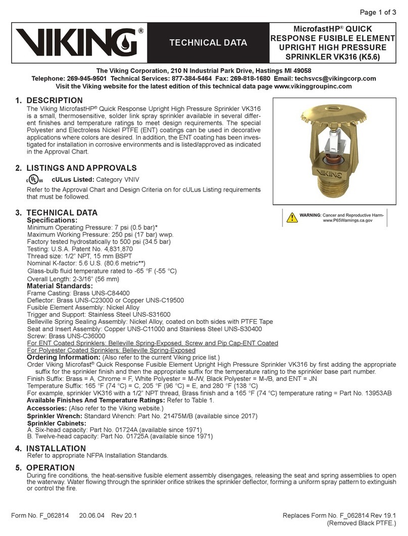
3: PRODUCT DESCRIPTION
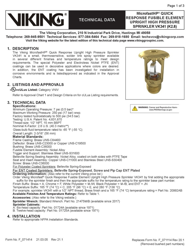
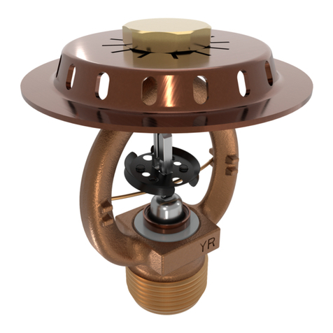
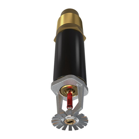
The Viking Model M Quick Response
Dry Upright Sprinkler is an assembly
consisting of a thermo-sensitive glass
bulb spray sprinkler permanently se-
cured to a special supply nipple.
The Upright Sprinkler frame and deflec-
tor are of the Model M design, equipped
with a rugged 3 mm glass bulb that
meets the response criteria for Quick
Response sprinklers. The sprinkler is
available inseveral temperatureratings
to meet design requirements.
The special supply nipple is designedto
prevent water from entering the nipple
before the sprinkler operates. This fea-
ture makes the Dry Upright Sprinkler
suitable for use in unheated spaces
above ceilings of heated rooms
equipped with wet sprinkler systems.
Model M Quick Response Dry Upright
Sprinklers may be installed on wet sys-
tems, dry systems, or preaction sys-
tems.
A chrome escutcheon is provided with
eachsprinkler,tocovertheceilingpene-
tration (see Figure 1). Model M Dry Up-
right Sprinklers feature a sealed brass
inlet and a durablethreadedsteel barrel
with an Electrodeposited Epoxy Base
coating.
The seal at the threaded end of the
assembly is held in place by force trans-
mitted from the compression screw,
throughtheglassbulbandinternalparts,
ontoaspecialsealingspring. Duringfire
conditions, the heat sensitive liquid in
the glass bulb expands, causing the
glass to shatter, releasing the internal
partstoopenthewaterway. Waterflowing
through the sprinkler orifice strikes the
sprinklerdeflector formingauniformspray
pattern to extinguish or control the fire.
Viking Dry Upright Sprinklers may be or-
dered, in 1/2" (12,7mm) increments, in
lengths ("B" dimension) from 4-1/2"
(114,3mm) to 49-1/2" (1257,3mm) long*.
(See Ordering Information.)
* Lengths over 49-1/2" (1257,3mm) are available,
with no approvals, on a "made to order" basis.
Contact manufacturer.
4. TECHNICAL DATA
Seechart(thispage)forlistofapprovals.
Approved to maximum length of 49-1/2"
(1257,3mm).
Glass Bulb Fluid Temperature rated to
-65oF (-55oC)
Ratedto175PSI(1207kPa)waterwork-
ing pressure.
Thread Size: 1" NPT.
Orifice Size: Nominal 1/2" (15mm).
K Factor: 5.5 U.S. (7,93 metric)7(all
approved lengths).
Minimum operating pressure: 7 PSI
(48,3 kPa).
Form No. F_031693
Sprinkler 107 a
TECHNICAL DATA MODEL M
QUICK RESPONSE
DRY UPRIGHT
SPRINKLER
March 21, 1996
Sprinkler Nominal Sprinkler Ceiling Temperature at Sprinkler
Temperature Temperature Rating Max. Ambient Max. Recommended Bulb Color
Classification (Fusing Point) Temp. Allowed 1Ambient Temp.2Color Coding3
Ordinary 135oF (57oC) 115oF (46oC) 100oF (38oC) Orange None
Ordinary 155oF (68oC) 135oF (57oC) 100oF (38oC) Red None
Intermediate 175oF (79oC) 155oF (68oC) 150oF (65oC) Yellow White
Intermediate 200oF (93oC) 180oF (82oC) 150oF (65oC) Green White
High 286oF (141oC) 266oF (130oC) 225oF (107oC) Blue Blue
Thread Nominal Dry Upright Nominal Order Length 4 Approval 5
Size Orifice Style K Factor Increment
N.P.T. Inches MM Description Base P/N 6 U.S. Metric7 Inches mm UL ULC FM NYC8 VDS LPC
1 inch 1/2 15 Plain Barrel 08417 5.5 7,93 1/2 12,7 Yes Yes -- -- -- --
4Minimum length ("B" Dimension) = 4-1/2 inches (114,3mm). Maximum standard length ("B" Dimension) = 49-1/2 inches (1257,3mm).
5This Chart shows the listings and approvals available at the time of printing. Other approvals are in process. Check with the
manufacturer for any additional approvals.
6Base part number shown. For complete part number, see price list.
7MetricK Factor shown is for use when pressure is measured in kPa. When pressure is measured in BAR, multiply the metric K factor
shown by 10.0.
8Acceptance for use by the City of New York Department of Buildings is pending.
FOOTNOTES
Model M
Quick Response
Dry Upright Sprinkler
Note: Units of measure in parentheses may be approximations.
R
1Based on National Fire Prevention and Control Administration Contract No. 7-34860.
2Based on NFPA-13. Other limits may apply depending on fire loading, sprinkler location and other
authority having jurisdiction requirements. Refer to specific installation standards.
3 Frames of decorative sprinklers are not color coded. Temperature rating is stamped on deflector.
Replaces page 107 a-c dated June 11, 1993
(Added ULC listing)
OBSOLETE
Factory tested pneumatically at 100 PSI
(685 kPa).
Spring: USA Patent No. 4,167,974
Bulb: USA Patent No. 4,796,710
SPRINKLER MATERIALS:
Frame: Brass Castings
UNS-C84400
Deflector: Brass
UNS-C26000
Bulb: Glass,
Nominal 3mm diameter
Seal: Teflon Tape
Spring: Nickel Alloy
Screw: Brass
UNS-C36000
Pip Cap: Brass
UNS-C31600
Seat: Copper
UNS-C21000
Orifice: Copper
UNS-C21000
Washer: Stainless Steel
UNS-S30400
Base: Brass UNS-C31600
Gasket: Buna N
Tube: JIC Hydraulic Steel Tube
Inlet: Brass UNS-C36000
Support (Internal): Steel UNS-G10080
Electrodeposited
Epoxy Base finish
Spring (Internal when "B" dimension
exceeds 37" (940mm):
Stainless Steel UNS-S30200
Barrel: Steel Tube
UNS-G10200
Electrodeposited
Epoxy Base finish (Black)
ESCUTCHEON MATERIAL:
Escutcheon: Brass UNS-C26000
(Decorative Chrome Finish)
ACCESSORIES:
Dry Sprinkler Wrench
Standard: PN 07297
Escutcheon: PN 01964B
Decorative Brass finish
(A chrome escutcheon is included
witheachModelMDryUprightSprin-
kler)
SPRINKLER FINISHES:
Plain Barrel with Brass Sprinkler
ORDERING INFORMATION:
Forpropershipmentspecify: model,fin-
ish, temperature rating, and length ("B"
Dimension) desired. Viking Dry Upright
Sprinklers are ordered in specific
lengthsnotedas the "B" dimension (see
Figure 1). For Viking Model M Dry Up-
right Sprinklers the "B" dimension is the
distance from the face of the fitting (tee),
into which the sprinkler is to be installed,
to thetop of the deflector(see Figure1).
5. AVAILABILITYANDSERVICE:
Viking Sprinklers are available through
a network of Domestic, Canadian, and
International Distributors. See the Yel-
low Pages of the telephone directory
(listed under "Sprinklers Automatic
Fire")or contactTheVikingCorporation.
6. GUARANTEES
For details of warranty, refer to Viking’s
current list price schedule or contact Vi-
king directly.
7. INSTALLATION
WARNING: Viking sprinklers are manu-
factured and tested to meet the rigid
requirements of approving agencies.
The sprinklers are designed to be in-
stalled in accordance with recognized
installation standards. Deviation from
the standards or any alteration to the
sprinkler after it leaves the factory in-
cluding, but not limited to, painting, plat-
ing, coating, or modification, may render
the sprinkler inoperative and will auto-
matically nullify the approval and any
guarantee madeby TheVikingCorpora-
tion.
A. Sprinklers are to be installed in ac-
cordance with the latest published
standardsoftheNational FireProtec-
tion Association, Factory Mutual,
Loss Prevention Council, Assemblee
Pleniere, Verband der Sachver-
sicherer or other similar organiza-
tions,andalso with provisionsofgov-
ernmental codes, ordinances, and
standards whenever applicable. The
use of Quick Response Dry Upright
Sprinklers may be limited due to oc-
cupancy and hazard. Refer to the
Authority Having Jurisdiction prior to
installation.
B. Sprinklers must behandled withcare.
They must be stored in a cool, dry
place in their original container.
Never install sprinklers that have
been dropped or damaged in any
way. Never install any glass bulb
sprinkler if the bulb is cracked or if
there is a loss of liquid from the bulb.
Never install sprinklers which have
been exposed to temperatures in ex-
cess of maximum ambient tempera-
ture allowed. Such sprinklers should
be destroyed immediately.
C. Model M Dry Upright Sprinklers are
not intended for use in corrosive en-
vironments. Use only sprinklers
listed for corrosive environments
when subject to corrosive atmos-
pheres.
WARNING: Dry Upright Sprinklers
MUST be installed into the 1" outlet of
acastironor malleableironteefitting
only.
1. DO NOT install the Dry Upright
Sprinkler into a threaded elbow,
coupling, or any other fitting that
could interfere with thread pene-
tration. Such installation will
damage the brass seal.
2. NEVER try to modify the Dry Up-
right Sprinkler. The sprinklers are
manufactured for a specific "B"
dimension and cannot be modi-
fied.
D.ModelMQuickResponseDryUpright
Sprinklers must be installed after the
pipingis in place topreventmechani-
cal damage. Install the sprinkler
above the piping, in the upright posi-
tion only. Wheninstalling DryUpright
Sprinklers on piping located close to
the ceiling it may be necessary to
lowerthe sprinklerintothe fittingfrom
above the ceiling. Before installing,
verifythatthe"B"dimensioniscorrect
and theappropriate model, style, and
temperature rating is used. When in-
stalling theDry Upright Sprinkler from
below the ceiling, verify that the hole
in the ceiling is a minimum 1-1/2"
(38,1mm) diameter.
1. Install the optional escutcheon (if
used)overthethreadedendofthe
Dry Upright Sprinkler barrel. Slide
the escutcheon past the external
threads.
Note:Wheninstallingthesprinkler
from above the ceiling, it will be
necessary to install the escutch-
eon after lowering the threaded
end of the sprinkler through the
ceiling penetration.
2. Apply a small amount of pipe joint
compound or tape to the external
threads of the sprinkler barrel
only, taking care not to allow a
build up ofcompound or tape over
the brass inlet and seal.
3. Install the sprinkler on the piping
using the special Dry Sprinkler
Wrenchonly,whiletakingcarenot
to damage the sprinkler. DO NOT
use a pipe wrench on the barrel of
the Dry Upright Sprinkler.
E. After installation, the entire sprinkler
systemmustbe testedinaccordance
withtherecognizedinstallationstand-
ards. The test is applied after sprin-
kler installation to insure no damage
has occurred to the sprinkler during
Sprinkler 107 b
TECHNICAL DATA
March 21, 1996
R
MODEL M
QUICK RESPONSE
DRY UPRIGHT
SPRINKLER
OBSOLETE
shipment and installation, and to
make certain the unit has been prop-
erly tightened. If a thread leak should
occur, normally the unit must be re-
moved, new pipe joint compound or
tape applied, and reinstalled. This is
due to the factthat when the joint seal
leaks, the sealing compound is
washed out of the joint.Air testingthe
sprinkler piping prior to testing with
water may be considered in areas
whereleakageduringtestingmustbe
prevented. Refer to the appropriate
technical data and the Authority Hav-
ing Jurisdiction prior to air testing the
sprinkler piping.
F. Wet pipe systems supplying Dry Up-
rightSprinklersmustbeprovidedwith
adequate heat. Refer to appropriate
installation standards.
8. MAINTENANCE
NOTICE: The owner is responsible for
maintaining the fire protection system
and devices in proper operating condi-
tion. For minimum maintenance and in-
spection requirements, refer to the Na-
tional Fire Protection Association Pam-
phlet that describes care and mainte-
nance of sprinkler systems. In addition,
the "Authority Having Jurisdiction" may
have additional maintenance, testing,
andinspectionrequirementswhichmust
be followed.
A. The sprinklers must be inspected on
a regularbasis for signs of corrosion,
mechanical damage, obstructions,
paint, etc. The frequency of the in-
spections may vary due to corrosive
atmospheres, water supplies and ac-
tivity around the device.
B. Sprinklers that have been field
painted, caulked, or mechanically
damaged must be replaced immedi-
ately. Sprinklers showing signs of
corrosion shall be tested and/or re-
placed immediately as required.
Quick Response Dry Upright Sprin-
klers that are 20 years old shall be
tested and/or replaced immediately
as required. Never attempt to repair
or reassemble a Dry Upright Sprin-
kler. Sprinklers that have operated
cannot be reassembled or re-used,
but must be replaced. When replac-
ing sprinklers, use only new sprin-
klers.
C. The sprinkler discharge pattern is
critical for proper fire protection.
Nothing should be hung from, at-
tached to, or otherwise obstruct the
discharge pattern. All obstructions
must be immediately removed or, if
necessary, additional sprinklers in-
stalled.
D. When replacing existing sprinklers,
the system must be removed from
service. Refertotheappropriatesys-
tem description and/or valve instruc-
tions. Prior to removing the system
from service, notify all Authorities
Having Jurisdiction. Consideration
should be given to employment of a
fire patrol in the effected area.
1. Remove the system from service,
draining all water and relieving all
pressure on the piping.
2.Using thespecial sprinkler wrench,
remove the old sprinkler and in-
stall the new unit. Care must be
taken to replace the sprinkler with
the proper model, style, "B" di-
mension, orifice size, and tem-
perature rating.
3. Place the system back in service
and secure all valves. Check and
repair all leaks.
E. Sprinkler systems that have been
subjected to fire must be returned to
service as soon as possible. The entire
system must be inspected for damage
and repaired or replaced as necessary.
Sprinklers that have been exposed to
corrosiveproductsofcombustionorhigh
ambient temperatures, but have not op-
erated, should be replaced. Refer to
the Authority Having Jurisdiction for
minimum replacement requirements.
Sprinkler 107 c
TECHNICAL DATA
March 21, 1996
1-5/8"
(41,3mm)
Ceiling
A minimum 1-1/2" (38,1mm)
diameter hole is required to
install sprinkler from below
ceiling.
Outside diameter: 1-5/16"
(33,4mm).
Outside diameter is the same
outside diameter as 1" (25mm)
schedule 40 pipe.
FOR "B"
1: Determine distance
from face of tee to
top of sprinkler
deflector.
2: Round to nearest
1/2" (12,7mm)
increment between
4-1/2" (114,3mm)
and 49-1/2"
(1257,3mm).
FIGURE 1
QUICK RESPONSE
MODEL M DRY UPRIGHT SPRINKLER
13/16"
(20,5mm)
Escutcheon 3-1/16"
(77,8mm)
R
MODEL M
QUICK RESPONSE
DRY UPRIGHT
SPRINKLER
OBSOLETE

Other manuals for M

6

Other Viking Irrigation System manuals

Viking VK250 Instruction manual

Viking

Viking VK250 Instruction manual

Viking MICROMATIC VK202 Instruction manual

Viking

Viking MICROMATIC VK202 Instruction manual

Viking MICROFAST VK355 Instruction manual

Viking

Viking MICROFAST VK355 Instruction manual

Viking VK531 Instruction manual

Viking

Viking VK531 Instruction manual

Viking SIN VK520 Instruction manual

Viking

Viking SIN VK520 Instruction manual

Viking FREEDOM VK4800 Instruction manual

Viking

Viking FREEDOM VK4800 Instruction manual

Viking SIN VK510 Instruction manual

Viking

Viking SIN VK510 Instruction manual

Viking MICROFAST VK306 Manual

Viking

Viking MICROFAST VK306 Manual

Viking MICROMATIC VK106 Instruction manual

Viking

Viking MICROMATIC VK106 Instruction manual

Viking VK3501 Instruction manual

Viking

Viking VK3501 Instruction manual

Viking VK2001 Instruction manual

Viking

Viking VK2001 Instruction manual

Viking FREEDOM VK498 Instruction manual

Viking

Viking FREEDOM VK498 Instruction manual

Viking Microfast M-5 Instruction manual

Viking

Viking Microfast M-5 Instruction manual

Viking VK520 Instruction manual

Viking

Viking VK520 Instruction manual

Viking VK3502 Instruction manual

Viking

Viking VK3502 Instruction manual

Viking VK514 Service manual

Viking

Viking VK514 Service manual

Viking VK500 Instruction manual

Viking

Viking VK500 Instruction manual

Viking VK1202 Instruction manual

Viking

Viking VK1202 Instruction manual

Viking K80 Instruction manual

Viking

Viking K80 Instruction manual

Viking VK570 Instruction manual

Viking

Viking VK570 Instruction manual

Viking FREEDOM VK4840 Instruction manual

Viking

Viking FREEDOM VK4840 Instruction manual

Viking MicrofastHP VK317 Instruction manual

Viking

Viking MicrofastHP VK317 Instruction manual

Viking FREEDOM VK479 Instruction manual

Viking

Viking FREEDOM VK479 Instruction manual

Viking ESFR User manual

Viking

Viking ESFR User manual

Popular Irrigation System manuals by other brands

GEM AQUARIUS F993 quick start guide

GEM

GEM AQUARIUS F993 quick start guide

Tyco RAVEN Institutional TY3281 manual

Tyco

Tyco RAVEN Institutional TY3281 manual

Eden 94154EDAMZ quick start guide

Eden

Eden 94154EDAMZ quick start guide

Globe GL4231 quick start guide

Globe

Globe GL4231 quick start guide

Tyco Fire Product CENTRAL BV4 instruction manual

Tyco Fire Product

Tyco Fire Product CENTRAL BV4 instruction manual

Autopot SmartPot 9 XL Set-up guidelines

Autopot

Autopot SmartPot 9 XL Set-up guidelines

Tyco DS-1 Series manual

Tyco

Tyco DS-1 Series manual

Toro 570Z Series installation instructions

Toro

Toro 570Z Series installation instructions

Tyco ESFR-17 quick start guide

Tyco

Tyco ESFR-17 quick start guide

Hunter Institutional Series manual

Hunter

Hunter Institutional Series manual

DX Engineering DXE-BCSO-3-075 manual

DX Engineering

DX Engineering DXE-BCSO-3-075 manual

Hoselink 5640-WG user manual

Hoselink

Hoselink 5640-WG user manual

Orbit ARC SPRINKLER user manual

Orbit

Orbit ARC SPRINKLER user manual

CloudRain CloudRain Controller user manual

CloudRain

CloudRain CloudRain Controller user manual

Hills Heritage Hoist 6-Line product manual

Hills

Hills Heritage Hoist 6-Line product manual

Tyco TY1136 manual

Tyco

Tyco TY1136 manual

Tyco Fire Product TY300-FRB instruction manual

Tyco Fire Product

Tyco Fire Product TY300-FRB instruction manual

Sime SENIOR INSTALLATION, USE, MAINTENANCE, SPARE PARTS

Sime

Sime SENIOR INSTALLATION, USE, MAINTENANCE, SPARE PARTS

manuals.online logo
manuals.online logoBrands
  • About & Mission
  • Contact us
  • Privacy Policy
  • Terms and Conditions

Copyright 2025 Manuals.Online. All Rights Reserved.