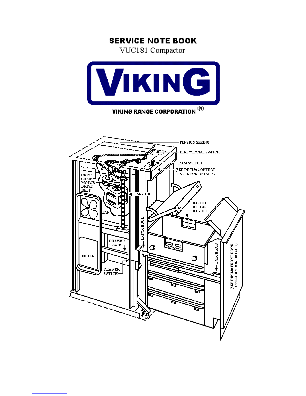
Viking Professional VUC181 Service manual


3
TABLE OF CONTENTS
DUC Cover------------------------------------------------------------------------------------ 00
Table of Contents---------------------------------------------------------------------------- 03
SERVICE INSTRUCTIONS
Back Panel---------------------------------------------------------------------------- 04
Side Panel----------------------------------------------------------------------------- 04
Frame Top Assembly---------------------------------------------------------------- 04
Door Front Panel Insert-------------------------------------------------------------- 04
Drawer Assembly--------------------------------------------------------------------- 05
Drawer Latch Mechanism----------------------------------------------------------- 05
Drawer Handle------------------------------------------------------------------------ 05
Drawer Track-------------------------------------------------------------------------- 06
Kick Board----------------------------------------------------------------------------- 06
Control Panel-------------------------------------------------------------------------- 06
Blower Motor-------------------------------------------------------------------------- 07
Drive Chain---------------------------------------------------------------------------- 07
Motor Drive Belt---------------------------------------------------------------------- 08
Ram Unit------------------------------------------------------------------------------- 09
Jack Screws---------------------------------------------------------------------------- 10
Motor Sprocket & Drive Pulley Assembly---------------------------------------- 11
Motor & Pulley------------------------------------------------------------------------ 11
Electrical Power Cord---------------------------------------------------------------- 12
Directional Switch-------------------------------------------------------------------- 12
Drawer Front Interlock Switch------------------------------------------------------ 12
Interlock Bypass Switch------------------------------------------------------------- 13
Ram Switch---------------------------------------------------------------------------- 13
Pictorial Wiring Diagram------------------------------------------------------------ 14
Schematic Wiring Diagram---------------------------------------------------------- 15
Service Tips------------------------------------------------------------------------------------- 16
Component Breakdown
Unit Cut-A-Way---------------------------------------------------------------------- 17
Frame Assembly--------------------------------------------------------------------- 18
Container Assembly----------------------------------------------------------------- 19
Ram Assembly----------------------------------------------------------------------- 20

4
SERVICING INSTRUCTIONS
NOTE: IT WILL BE NECESSARY TO
REMOVE THE UNIT FROM ITS
INSTALLED POSITION.
NOTE: DISCONNECT ELECTRICAL
POWER SUPPLY BEFORE SERVICING
UNIT.
Top (Fig. 1)
1. Remove three top retaining screws (1)
from rear of compactor.
2. Slide top toward rear to disengage from
key slots. Lift off top
BACK PANEL (Fig. 1)
1. Remove three screws (1) at top.
2. Remove four screws (2) from each side.
3. Remove two screws (3 & 6) from back
panel. Remove plate (4) and slide relief
(5) up and out of slot. Feed cord
through rectangular hole in back panel.
SIDE PANELS (Fig. 1)
1. Remove top and back panel.
2. Open litter bin door and remove two
retaining screws (9).
3. Open drawer and remove remaining
front retaining screws (7 & 8).
FRAME TOP ASSEMBLY (Fig. 10)
1. Remove top, back panel and side panels.
2. Remove three jack screw retainer nuts
(4).
3. Remove two truss head retaining screws
(3).
4. Lift off enclosure plate (1).
5. Remove four truss head retaining screws
(2).
6. Disconnect the two ram switch leads
from start-stop program switch (3) and
remove frame top assembly.
DOOR FRONT PANEL INSERT (Fig. 2)
1. Open door and remove three retaining
screws from pull handle (1) and remove
handle.

5
2. Slide panel insert out through opening in
top of litter bin door.
DRAWER ASSEMBLY (Fig. 3)
1. With drawer forward, remove two
drawer retaining screws (1), from
drawer tracks.
2. Remove drawer from drawer tracks.
DRAWER FRONT PANEL INSERT
(Fig. 4)
1. Remove drawer.
2. Stand drawer on rear and remove the
three trim panel retaining screws (1)
from bottom of drawer.
3. Remove bottom trim. Slide panel insert
out through opening in bottom of drawer
front.
DRAWER LATCH MECHANISM (Fig. 3)
1. To service the drawer latch rod, springs,
and hook assembly, remove the upper
three retaining screws (2) from each side
of drawer panel.
2. Loosen, but do not remove, the bottom
retaining screw (3) on each side of the
drawer panel.
3. Pivot drawer front away from storage
bin.
4. Disengage latch rod hook from handle
and remove latch rod assembly from
drawer front.
DRAWER HANDLE (Fig. 5)
1. It is not necessary to remove the
drawer front to service drawer
handle or hinge & mounting bracket
assembly.
2. Use a short handled Phillips
screwdriver to remove retaining
screws (1) to remove drawer handle.
3. To remove hinge & handle
mounting bracket assembly,
withdraw the two screws (2) from
inside storage cover.

6
DRAWER TRACK / SPRING (Fig. 6)
1. Remove top.
2. Remove back panel.
3. Remove side panels.
4. Remove drawer.
5. Loosen, then remove the two track
mounting nuts and washers (1), (two in
front and two in back).
6. Remove bolts and washers, then
disconnect springs (2) and remove
drawer tracks.
7. When installing drawer tracks, first
connect springs to frame (spring hooks
facing out), then to track mounting
brackets.
8. Force the track downward until the hole
in the track mounting bracket lines up
with the slot in the frame, permitting
installation of the bolt, washer and nut
NOTE: At reassembly the bolt head should
be on the inside of the frame.
KICKBOARD
1. Remove drawer.
2. Stand drawer on rear and remove four
retaining screws from kickboard and
kickboard support plate.
3. Remove kickboard and support plate.
CONTROL PANEL (Fig. 7)
1. Open litter bin door and remove two
retaining screws (1) from inside top of
litter bin.
2. Slide console forward to clear unit and
disconnect wire leads from charcoal air
filter switch, and key lock switch.
3. Remove control panel (2).

7
1. Connect electrical power supply and
run ram to bottom position.
2. Disconnect power supply.
3. Remove back panel.
4. Disconnect two lead wires from
blower motor.
5. Remove two blower motor
mounting screws (1).
6. Remove blower motor and fan from
housing.
NOTE: The nylon blower motor fan is
lightly pressed onto the motor shaft.
This is removable for service
replacement.
CHAIN TENSION REGULATOR (Fig. 9)
1. Remove top and top frame cover
plate.
2. Remove chain tension regulator
spring (2).
3. Remove retaining nut (1) and lock
washer from idler arm.
4. Remove screw (5) from idler plate
assy. (4). Shift idler plate to allow idler
arm (3) to clear sprocket cover.
5. Lift off idler arm (3).
DRIVE CHAIN
1. Remove top, back panel, side panel
and frame top assembly.
2. Remove chain tension regulator
spring (2, Fig. 9).
3. Pull drawer half way open. locate
ram on top of drawer. Ram can be
operated manually by using the 5/8” hex
socket on the motor sprocket (6, Fig.
11).
4. Remove the four sprocket cover and
brace screws from the ram top brace.
Then loosen (only) the two remaining
screws in the ram top brace. Remove
the drive sprocket covers (1, 3 and 6,
Fig.10).

8
5. Remove chain (5, Fig.10) from sprocket.
6. Install replacement chain making certain
chain is properly positioned onto drive
and idler sprockets. Install tension
regulator spring (4, Fig.10).
CAUTION: All three drive sprockets must
be level (same height). Measure distance
from top of each jack screw to top of drive
sprocket.
7. Adjust drive chain for correct tension by
loosening the four motor sprocket
bracket mounting blots (7, Fig.10), and
moving the sprocket in the proper
direction to the distance from the center
of the two idler sprocket retaining
screws is 6–¼” minimum to 6-1/2”
maximum as shown (see Fig. 9). It is
IMPORTANT this distance is
maintained.
8. The four sprocket bracket mounting
bolts (7, Fig.10) must be securely
tightened. Check the two side flange
bearing mounting bolts (8, Fig.10) and if
necessary, retighten. Recheck the chain
adjustment.
9. Reinstall drive sprocket covers and ram
top brace
10. Manually rotate motor sprocket
clockwise to check for free operation of
ram drive mechanism.
MOTOR DRIVE BELT
To remove:
1. Remove top and top frame cover plate.
2. Locate ram approximately 4 inches from
top position. Ram can be operated
manually by using the 5/8” socket on the
motor sprocket (6, Fig.11).
3. Remove chain tension regulator spring
(4, Fig.10).
4. Loosen four motor mounting bolts (2,
Fig.10). Slide motor toward sprocket
drive pulley and remove belt.
To replace:
5. Position belt around motor sprocket
drive pulley.
6. Move belt toward motor and around
motor pulley making certain teeth in belt
are meshed in both sprocket drive pulley
and motor pulley.
7. Slide motor toward front and finger
tighten mounting blots (2, Fig.10)

9
8. Rotate motor sprocket manually
approximately two revolutions to align
belt.
9. Loosen motor mounting bolts (2,
Fig.10), slide motor toward front until
belt is taut (approximately 30 to 40 lbs.).
10. Replace chain tension regulator spring
(4, Fig.10).
RAM UNIT
1. Remove top, back panel, side panels and
frame top assembly.
2. Pull drawer out half way.
3. Locate ram on top of drawer. Ram can
be operated manually by using the 5/16”
hex socket on the motor sprocket (6,
Fig.11).
4. Remove Drive Chain (5, Fig.11).
5. Unscrew all three drive sprockets (1,
Fig.12) from jack screws (2, Fig.12).
6. Remove drive sprocket grease retainers
(Fig.13).
CAUTION: DO NOT INTERCHANGE
jack screw sprocket assemblies. On
reinstallation be certain to return each
sprocket assembly to its original jack screw
location.

10
7. Remove drawer interlock actuator
bracket from rear of upper ram housing.
8. Loosen main wiring harness by
removing strain relief bushing (1,
Fig.14) from frame and harness retainer
(4, Fig. 17) from idler plate.
9. Move wiring harness aside. Grasp side
of ram and lift from jack screws.
NOTE: Should further disassembly be
requested for the ram, disconnect all ram
wiring connections.
JACK SCREWS
1. Remove ram. (Jack screws are now
accessible for removal).
2. Remove hex mounting bolts (2, Fig.15).
3. Pull jack screw (1, Fig.15) down
through hole in frame and withdraw jack
screw retainer out (3, Fig.15) and screw
retaining plate (4, Fig.15) from
underside of cross member of frame.
CAUTION: At reassembly of jack screw
make certain square end of jack screw (1,
Fig.16) extends through square hole and is
flush with bottom of screw retainer plate (2,
Fig.16). Screw retainer plate (2, Fig.16)
must be drawn up tight against the mating
face of the jack screw retainer nut (3,
Fig.16).

11
MOTOR SPROCKET AND DRIVE
PULLEY ASSEMBLY (Fig.17)
1. Remove top, top frame cover plate and
one side panel.
2. Ram must be located in “top” position
(if necessary, use 5/8” hex socket
wrench to manually raise ram).
3. Remove drawer.
4. Tape the ram spacer to ram top for
holding spacer in place before removing
ram bottom. (Use 6 or 8 strips of
masking tape.)
5. Remove four retaining screws from ram
bottom.
NOTE: To reassemble ram bottom, masking
tape should again be used to hold ram
bottom in place (6 or 8 strips are necessary).
Start one of the front retaining screws to
secure the ram bottom. Install remaining
screws. Tighten securely and remove tape.
6. Loosen four mounting bolts (1) and
slide motor sprocket bracket toward
motor.
7. Remove chain tension regulator spring
(2).
8. Disengage chain (5) from motor
sprocket.
9. Remove four motor sprocket bracket
mounting bolts (1) and lower the drive
pulley assembly.
NOTE: Repairs to the motor sprocket and
drive pulley assembly should not be
attempted. If unit is faulty, replace with
complete new unit.
MOTOR AND PULLEY (Fig.17)
1. Remove top and top frame cover plate.
2. Remove drawer.
3. Locate ram in “down” position. (If
necessary, use 5/8” hex socket to
manually lower ram.)
4. Remove four retaining screws from ram
bottom.
5. Remove ram bottom and the ram spacer.
6. Disconnect motor lead wires.
7. Loosen motor mounting bolts (3) and
slide motor toward motor drive sprocket
assembly.
8. Remove motor drive belt.
9. Insert ram bottom and spacer and place
as support under motor. Remove motor
mounting bolts (3). Slightly raise ram
manually to clear top of motor. Lower
and remove motor.

12
SWITCHES-CONTROL PANEL (Fig.18)
[Filter switch (1), Key lock switch (2)]
1 Remove control panel.
2 Remove lead wires from switches.
3 Remove filter switch by depressing tabs
together and pulling switch out of panel.
4 Remove key switch, retaining nut and
then the switch.
CAUTION: Leak wire identifications
MUST correspond with switch terminals.
ELECTRICAL POWER CORD
1. Remove L.H. side panel.
2. Remove back panel.
3. Remove ground screw, wire connector
from white neutral lead and disconnect
two switch terminal connections from
drawer front interlock and bypass
interlock switch.
4. Remove strain relief bushing from left
front vertical frame upright.
5. Remove electrical power cord.
6. When reinstalling electrical power cord,
feed cord through cord clamps.
DIRECTIONAL SWITCH (Fig.18)
1. Remove top and top frame cover plate.
2. Disconnect lead wires from switch (3).
CAUTION: At reassembly, lead wire
identification MUST correspond with switch
terminals.
3. Remove switch retaining screws and the
switch.
DRAWER FRONT INTERLOCK SWITCH
1. Remove top and left side panel.
2. Remove interlock switch lead wires.
3. Remove switch mounting screws and
the switch.

13
INTERLOCK BYPASS SWITCH
(Fig.10)
1. Remove top and side panel.
2. Remove interlock switch lead wires.
3. Remove switch mounting screws
and the switch (2).
RAM SWITCH (Fig.19)
1. Remove top and top frame cover
plate.
2. Disconnect two lead wires from
switch (1).
3. Remove switch retaining screws and
the switch.
4. In reassembling switch make sure it
is correctly adjusted. Rotate in slot
as necessary.

14
PICTORIAL WIRING DIAGRAM

15
SCHEMATIC WIRING DIAGRAM

16
VIKING COMPACTOR ** SERVICE TIPS **
CONDITION POSSIBLE CAUSE REMEDY
Motor runs but 1. Motor pulley, motor sprocket, 1.1 Replace pin(s)
ram inoperative drive sprocket or drive pulley 1.2 Replace drive belt
is inoperative 1.3 Replace drive chain
1.4 Replace pulleys or sprockets
Ram stuck in “down” 1. Malfunction of directional 1.1 Replace directional switch
Position switch.
Ram operates continuously 1. Malfunction of ram switch 1.1 Adjust or replace ram switch
2. Misalignment of start 2.1 Realign start switch button.
Switch button
Drawer will not close 1. Drawer latch mechanism 1.1 Adjust latch rod for proper align-
misaligned. ment with drawer track hooks.
2. Drawer track malfunction 2.1 Clean and loosen or replace
drawer track.
2.2 Replace drawer spring.
3. Drawer latch rod will not slide 3.1 Apply a small amount of lubri-
over cam on drawer slide hooks. cant (grease) on the drawer slide
Hook cam surface to allow drawer
Latch to slide on cam surfaces.
Drawer will not open 1. Drawer kickboard drags on floor. 1.1 Adjust leveling legs.
1.2 Replace drawer springs.
If required.
2.Malfunction of directional switch 2.1 See “Ram stuck in down” position.
3. Drawer latch mechanism 3.1 Adjust or replace malfunction
malfunctions. Parts.
4. Trash jamming drawer. 4.1 Remove trash
5. Malfunctioning tracks. 5.1 Clean, lubricate or replace
as required.
6. Track spring inoperative. 6.1 Correct or replace.
Compactor will not operate 1. No electric power to compactor 1.1 Make sure compactor
is “plugged in”.
1.2 Check fuse or circuit breaker.
2. Drawer not completely closed 2.1 Close drawer.
3. Key in locked position. 3.1 Turn key to unlock.
Motor will not operate 1. Improper electrical connections. 1.1 Check and correct.
2. Motor inoperative. 2.1 Replace motor.
Odor 1. Fully absorbed charcoal air filter. 1.1 See “Use and Care Guide”.
2. Inoperative blower motor. 2.1 Check electrical connection.
2.2 Replace motor.
Clearance between drawer 1. Improper drawer and /or litter 1.1 Align as needed.
and litter bin door uneven bin alignment.
**A properly operating compactor will smash 3 #2 size cans to ¼ their original height with cans placed on a 6”
wood block. When making this test the cans should have their lids removed. #2 size cans are approximately 3 ½” in
diameter and 4 ¼” high.

17
DUC180 CUT-A-WAY

18
DUC180 FRAME ASSY.

19
DUC 180 CONTAINER ASSEMBLY

20
RAM ASSEMBLY

Viking Range Corporation
111 Front Street, Greenwood, Mississippi (MS) 38930 USA (662) 455-1200
Viking products are marketed under the Ultraline brand name in Canada Specifications subject to change without notice
F90199 (LP10/02)
Other manuals for Professional VUC181
2
Table of contents
Other Viking Trash Compactor manuals

Viking
Viking Designer DFC180 User manual

Viking
Viking Professional VUC181 User manual

Viking
Viking Professional VUC181 User manual

Viking
Viking Designer DUC180 User manual

Viking
Viking F1213F User manual

Viking
Viking Designer Series User manual

Viking
Viking FCU150 User manual

Viking
Viking Designer DFC180 User manual

Viking
Viking FCU150 User manual

Viking
Viking FCU150 Installation guide