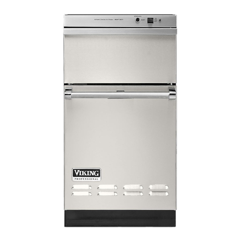
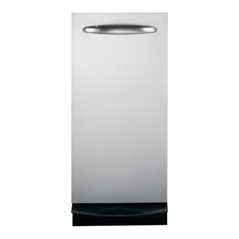
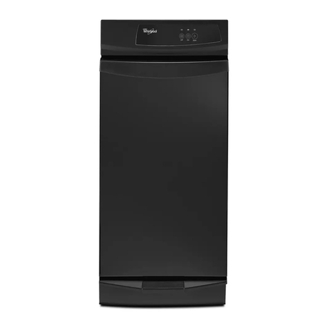
Viking Designer DUC180 User manual

INSTALLATION
INSTRUCTIONS
UNDERCOUNTER TRASH COMPACTOR
Retain for Future Reference
Viking Range Corporation
111 Front Street
Greenwood, Mississippi 38930 USA
(662) 455-1200
IMPORTANT - PLEASE READ AND FOLLOW
•Before beginning, please read these instructions completely and carefully.
•Do not remove permanently affixed labels, warnings, or plates from the product. This may void the warranty.
•Please observe all local and national codes and ordinances.
•Please ensure that this product is properly grounded.
•The installer should leave these instructions with the consumer who should retain for local inspector’s use and for
future reference
BEFORE YOU START INSTALLATION
Proper installation is your responsibility. Make sure you have everything necessary for correct installation. It is the
personal responsibility and obligation of the customer to contact a qualified installer to assure that electrical installation
meets all local and national codes and ordinances.
Grounded electrical outlet is required. (See “Electrical Requirements”)
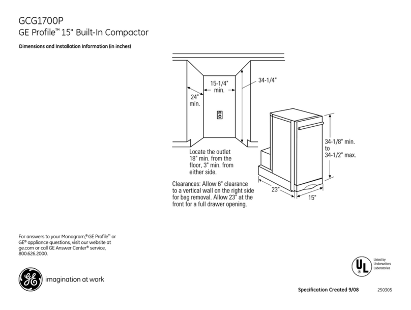
Check the location where the compactor will be installed. Compactor is designed for recessed installation. Cabinet
opening should be square. You should be able to fully open the compactor drawer. Allow 25” (63.5 cm) in front of
compactor to remove drawer. Six inches of clearance is needed on the right side of the compactor drawer to be able
to remove basket/bag.
WARNING: FIRE HAZARD
Do not let any item fall or collect behind the compactor. To do so may result in a fire.
FFRROONNTTRREEAARRSSIIDDEE
Electric/Cord Data
•2-wire with ground/ 3 prong plug
•bracket to end - 54” (137.2 cm)
•total length - 72” (182.9 cm)
•115 VAC/60 hz
•separate 15 amp min.
17 13/16”
(45.2 cm)
Min.
34 1/8”
(86.7 cm)
Max.
35 1/2”
(90.2 cm)
3 1/2”
(8.9 cm)
21 7/8”
(49.2 cm)
25 7/8” (65.7 cm)
23 7/8” (60.6 cm)
2 7/8”
(7.3 cm)

2
Electrical Requirements
Important: Observe all governing codes and ordinances.
WARNING: ELECTRICAL SHOCK HAZARD
•Electrical ground is required on this appliance.
•Improper connection of the equipment-grounding conductor can result in electric shock.
•Check with a qualified electrician if you are in doubt as to whether the appliance is properly grounded.
•Do Not modify the plug on the power supply cord. If it will not fit the outlet, have a proper outlet installed by a
qualified electrician.
•Do Not use an extension cord with this appliance. Such use may result in a fire, electrical shock or other personal
injury.
•Do Not have a fuse in the neutral or grounding circuit. A fuse in the neutral or grounding circuit could result in
electrical shock.
Failure to follow these instructions could result in fire, electrical shock or other personal injury.
A 115 volt, 60 Hz fused electrical supply is required. (Time-delay fuse or circuit breaker is recommended). It is
recommended that a separate circuit serving only this appliance be provided.
ReCOMMENDED GROUNDING METHOD
DDooNNoott,,uunnddeerraannyycciirrccuummssttaanncceess,,rreemmoovveetthheeppoowweerrssuuppppllyyccoorrddggrroouunnddiinnggpprroonngg..
For your personal safety, this appliance must be grounded. This appliance is equipped with a power supply cord
having a 3-prong grounding plug. To minimize possible shock hazard, the cord must be plugged into a mating 3-
prong, grounding type, wall receptacle, grounded in accordance
with the National Electrical Code ANSI/NFPA 70 latest edition and
all local codes and ordinances. If a mating wall receptacle is not
available, it is the personal responsibility and obligation of the
customer to have a properly grounded, 3-prong, wall receptacle
installed by a qualified electrician.
CUTOUT CLEARANCES
1/4” (.6 cm)
Min. clearance
from
compactor
top to
underneath
side of
countertop
24”
(61.0 cm)
Min.
18” Min.
(45.7 cm)
34 1/4”
(87.0 cm)
Min.
12” (30.5 cm)
Min.
3-prong
grounding-type
wall receptacle
grounding
prong
3-prong
grounding
plug
power supply cord
6” (15.2 cm)
clearance right side of drawer
for bag removal
25” (63.5 cm) clearance is
needed to fully open or
remove compactor drawer

4
3/4” (1.9 cm) thick
Side View
1 3/16” (3.0 cm)
28-1/4”
(71.8 cm)
1-15/16” (3.7 cm)
1-5/16” (3.3 cm)
Minimum distance for
handle holes from
top of overlay panel.
Maximum distance for handle holes from centerline.
Holes can be drilled anywhere in between
7-1/4”
(18.4 cm)
7-1/4”
(18.4 cm)
Two 3/32” (.094 cm) dia. holes -
1/4” (0.6 cm) deep.
CCuussttoommPPaanneell--BBaacckkVViieeww
Detail A
1/16” x 45o
chamfer
CUstom front panel installation (dfc models)
The Designer Full Overlay model should be installed with a locally supplied custom front panel. All parts needed to
install the panel come standard with the Designer Full Overlay model trash compactor. A handle should be used on
the custom front panel rather than a knob because a knob does not provide enough grip. Also note that the handle
should be attached to the panel before installing the front panel onto the compactor. See “Installing Custom Front”
section below for detailed information on attaching front panel to compactor. Mounting hardware for the handle must
be flush to the overlay panel.
CCuussttoommFFrroonnttPPaanneellDDiimmeennssiioonnss
Width 17-3/16” (43.7 cm)
Height 28-1/4” (71.8 cm)
Thickness 3/4” (1.9 cm)
Weight up to 25 pounds (11.4 kg.)

5
IIlllluussttrraattiioonn##33IIlllluussttrraattiioonn##44
IIlllluussttrraattiioonn##11IIlllluussttrraattiioonn##22
IInnssttaalllliinnggCCuussttoommFFrroonntt((DDFFCCmmooddeellssoonnllyy))
1. Prepare custom front panel and handle. (See information on p. 4 for details/dimensions.)
2. Placed prepared custom front panel on the ledge of the unit. (See Illustration #1).
3. Attach to unit by placing two (2) #10 x 1/2” screws in the lower most holes and screwing through the pilot holes on the
overlay. (See illustration #2). Loosen screws and center panel if needed. Retighten lower most screws after adjusting.
4. Secure the overlay panel by using the remaining seventeen (17) #10 x 1/2 screws. (See illustration #3).
5. Install the storage compartment cover with two (2) #8 x 3/8” wafer head screws. (See Illustration #4).
Ledge for panel
Other manuals for Designer DUC180
1
Table of contents
Other Viking Trash Compactor manuals

Viking
Viking Professional VUC181 User manual

Viking
Viking FCU150 User manual

Viking
Viking Designer DFC180 User manual

Viking
Viking Professional VUC181 User manual

Viking
Viking Designer DFC180 User manual

Viking
Viking Designer Series User manual
Viking
Viking Designer DUC180 User manual
Viking
Viking Professional VUC181 Service manual

Viking
Viking FCU150 Installation guide

Viking
Viking FCU150 User manual