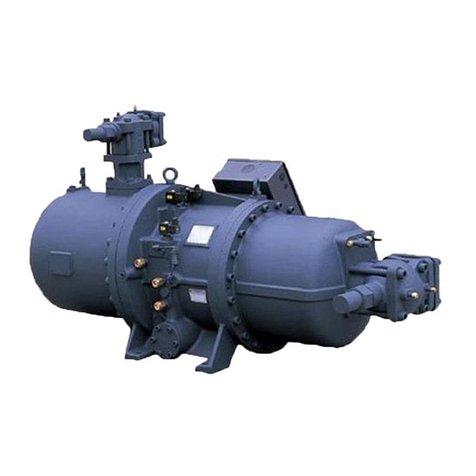
Vilter VSS 451-1801 Operation manual

1
VPN 35391S
February2006Rev.05
Price $ 60.00

2

3
ImportantNote:
READ CAREFULLY BEFORE INSTALLING AND STARTING YOUR COMPRESSOR.
The following instructions have been prepared to assist in installation, operation and removal of Vilter Single
Screw Compressors. Following these instructions will result in a long life of the compressor with satisfactory
operation.
The entire manual should be reviewed before attempting to install, service or repair the compressor.
A refrigeration compressor is a positive displacement machine. It is designed to pump superheated
vapor. The compressor must not be subjected to liquid carry over. Care must be exercised in properly
designing and maintaining the system to prevent conditions that could lead to liquid carry over. Vilter
Manufacturing Corporation is not responsible for the system or the controls needed to prevent liquid
carry over and as such Vilter Manufacturing Corporation cannot warrant equipment damaged by im-
properly protected or operating systems.
Vilter screw compressor components are thoroughly inspected at the factory, assuring the shipment of a
mechanically perfect piece of equipment. Damage can occurin shipment, however. For this reason, the
units should be thoroughly inspected upon arrival. Any damage noted should be reported immediately
to the Transportation Company. This way, an authorized agent can examine the unit, determine the
extent of damage and take necessary steps to rectify the claim with no serious or costly delays. At the
same time, the local Vilter representative or the home office should be notified of any claim made.
All inquires should include the Vilter order number, compressor serial and model number. These can be
found on the compressor name plate on the compressor.
All requests for information, services and or parts should be directed to:
Vilter Manufacturing Corporation
Customer Service Department
5555 South Packard Ave
P.O. Box 8904
Cudahy, WI 53110-8904 USA
Telephone: 1-414-744-0111
Fax:1-414-744-3483
e-mail: [email protected]
Equipment Identification Numbers:
Vilter Order Number: __________________________Serial Number: _____________

4
Table of Contents
LONG TERM STORAGE REQUIREMENTS ......................................................................................................................................... 8
DOMESTIC TERMS and CONDITIONS .............................................................................................................................................. 10
EXPORT TERMS and CONDITIONS ................................................................................................................................................... 12
STANDARDVILTER WARRANTY STATEMENT .............................................................................................................................. 14
STANDARD VILTER 5/15 WARRANTY STATEMENT ..................................................................................................................... 15
DESCRIPTION ........................................................................................................................................................................................ 16
SYMBOLSAND MEANINGS ............................................................................................................................................................... 18
InstallationSection ...................................................................................................... 19
DELIVERYINSPECTION....................................................................................................................................................................... 21
UNITWEIGHTS ...................................................................................................................................................................................... 21
FOUNDATIONS ...................................................................................................................................................................................... 21
LOCATING UNIT - DRIVE COUPLINGALIGNMENT ....................................................................................................................... 21
SYSTEM PIPING .................................................................................................................................................................................... 21
ELECTRICAL CONNECTIONS ............................................................................................................................................................. 23
TESTING REFRIGERATION SYSTEM FOR LEAKS .......................................................................................................................... 23
Ammonia Systems ........................................................................................................................................................................... 23
Halocarbon Refrigerant Systems ..................................................................................................................................................... 24
Evacuating The System .................................................................................................................................................................... 24
UNIT OIL CHARGING ........................................................................................................................................................................... 25
Oil For Single Screw Compressors.................................................................................................................................................. 25
SYSTEM REFRIGERANT CHARGING ................................................................................................................................................ 25
Low Side Equipment................................................................................................................................................................................ 26
Compressors ............................................................................................................................................................................................. 26
Condensers ............................................................................................................................................................................................... 26
Controls .................................................................................................................................................................................................... 26
Initial Charging – High Side Charging .................................................................................................................................................... 26
MAINTENANCE SUGGESTIONS ......................................................................................................................................................... 27
Daily ................................................................................................................................................................................................. 27
Weekly .............................................................................................................................................................................................. 27
Monthly ............................................................................................................................................................................................ 27
Trimonthly ........................................................................................................................................................................................ 27
Yearly................................................................................................................................................................................................ 27
System Leaks.................................................................................................................................................................................... 28
Year Round Operation...................................................................................................................................................................... 28
“STOPCHECK” INSTALLATION......................................................................................................................................................... 29
COUPLINGS INSTALLATIONANDALIGNMENT ............................................................................................................................. 30
Hub Mounting .................................................................................................................................................................................. 30
Straight Bore .................................................................................................................................................................................... 30
Taper Bore ........................................................................................................................................................................................ 30
Shaft Alignment. .............................................................................................................................................................................. 31
Final assembly . ............................................................................................................................................................................... 32
Disc Pack Replacement.................................................................................................................................................................... 32
SLIDE VALVEACTUATOR ................................................................................................................................................................... 34
ACTUATOR MOTOR CONTROL MODULE CALIBRATION PROCEDURE.................................................................................... 34
SLIDE VALVE TROUBLE SHOOTING GUIDE ................................................................................................................................... 37

5
Table of Contents
OperationSection........................................................................................................ 41
OIL SYSTEM ........................................................................................................................................................................................... 43
Non-Vilter Oil Notice ...................................................................................................................................................................... 42
Oil Charge....................................................................................................................................................................................... 43
Oil Filter ........................................................................................................................................................................................... 43
Filter Removal and Installation, all VSR Units. ............................................................................................................................. 43
Filter Removal, VSS and VSM Units.............................................................................................................................................. 44
Filter Removal, VSS and VSM Units . ........................................................................................................................................... 44
Oil Pressure Regulating ................................................................................................................................................................... 45
Oil Cooling ....................................................................................................................................................................................... 45
Water Cooled Oil Cooler.................................................................................................................................................................. 45
Liquid Injection Oil Cooling. ........................................................................................................................................................... 46
V-PLUS Oil Cooling System............................................................................................................................................................ 46
Thermosyphon Oil Cooling .............................................................................................................................................................. 47
CONTROL SYSTEM .............................................................................................................................................................................. 47
Screw Compressor Control And Operation ..................................................................................................................................... 47
Starting, Stopping and Restarting the Compressor ......................................................................................................................... 47
Slide Valve Control .......................................................................................................................................................................... 48
Slide Valve Motor Location............................................................................................................................................................. 49
Oil Separator Heater ......................................................................................................................................................................... 49
Econ-O-Mizer Controls ................................................................................................................................................................... 49
Safety Setpoints................................................................................................................................................................................ 49
Oil Pressure ...................................................................................................................................................................................... 49
Discharge Pressure ........................................................................................................................................................................... 49
Suction Pressure ............................................................................................................................................................................... 50
Oil Filter Differential....................................................................................................................................................................... 50
Oil Temperature ............................................................................................................................................................................... 50
Discharge Temperature .................................................................................................................................................................... 50
INITIALSTART-UP ................................................................................................................................................................................. 50
Setting of Controls ........................................................................................................................................................................... 50
Valve Settings ................................................................................................................................................................................... 50
Oil Separator .................................................................................................................................................................................... 50
V-PLUS Oil Cooling ........................................................................................................................................................................ 51
Liquid Injection Oil Cooling ............................................................................................................................................................ 51
Compressor Pre Start-Up Check List .............................................................................................................................................. 51
Stop Check Operation...................................................................................................................................................................... 52
Pre-Start Up...................................................................................................................................................................................... 53
PRE START-UP CHECKLIST - FIELD PIPING AND MECHANICAL REQUIREMENTS .............................................................. 54
PRE START-UP CHECKLIST - FIELD WIRING REQUIREMENTS ................................................................................................. 55
Service Section............................................................................................................. 56
GENERAL COMMENTS ........................................................................................................................................................................ 58
PREPARATION OF UNIT FOR SERVICING ........................................................................................................................................ 58
REMOVAL OF COMPRESSOR FROM THE UNIT ............................................................................................................................ 58
INSTALLATION OF THE COMPRESSOR ............................................................................................................................................ 59
LEAK CHECKING UNIT........................................................................................................................................................................ 59
ANNUALINSPECTION ......................................................................................................................................................................... 60
NORD-LOCKWASHERS ....................................................................................................................................................................... 61
GATE ROTOR ASSEMBLY .................................................................................................................................................................... 62
REMOVAL (All VSS and VSR Models)................................................................................................................................................. 62
REMOVAL (ALL VSM MODELS) ......................................................................................................................................................... 64
INSTALLATION (All VSS and VSR Models) ........................................................................................................................................ 66
INSTALLATION (All VSM Models) ...................................................................................................................................................... 68
6
Table of Contents
Service Section Cont..............................................................................................................................................................
GATE ROTOR BLADE REMOVAL ....................................................................................................................................................... 69
GATE ROTOR BLADE INSTALLATION .............................................................................................................................................. 69
GATE ROTOR THRUST ......................................................................................................................................................................... 70
BEARING REMOVAL GATE ROTOR THRUST .................................................................................................................................. 70
BEARING INSTALLATION GATE ROTOR ROLLER.......................................................................................................................... 71
GATE ROTOR ROLLER BEARING REMOVAL .................................................................................................................................. 72
GATE ROTOR ROLLER BEARING INSTALLATION.......................................................................................................................... 72
INPUT SHAFT SEAL REPLACEMENT ................................................................................................................................................ 73
INPUT SHAFT SEAL REMOVAL .......................................................................................................................................................... 73
SHAFT SEALINSTALLATION .............................................................................................................................................................. 74
MAIN ROTOR ASSEMBLY ................................................................................................................................................................... 75
INSPECTION OF SLIDE VALVE ASSEMBLIES IN THE COMPRESSOR......................................................................................... 76
REMOVAL SLIDE VALVE ..................................................................................................................................................................... 76
CARRIAGE ASSEMBLIES .................................................................................................................................................................... 76
INSTALLATION OF SLIDE VALVE CARRIAGEASSEMBLIES ........................................................................................................ 77
CAPACITYAND VARIABLE VOLUME RATIO CONTROL ASSEMBLY ........................................................................................ 78
OPTICAL SLIDE VALVEACTUATOR REMOVAL .............................................................................................................................. 78
OPTICALSLIDE VALVEACTUATOR INSTALLATION ..................................................................................................................... 79
GEAR MOTOR TO OPTICAL SLIDE VALVE ACTUATOR ................................................................................................................ 80
CONVERSION, INSTALLATION OF ACTUATOR............................................................................................................................... 80
COMMAND SHAFTASSEMBLY REMOVAL ..................................................................................................................................... 80
COMMAND SHAFTASSEMBLY INSTALLATION ............................................................................................................................. 81
COMMAND SHAFT BEARINGAND O-RING SEAL REPLACEMENT ........................................................................................... 81
COMMAND SHAFT BEARINGAND O-RING SEALREASSEMBLY .............................................................................................. 82
DISCHARGE MANIFOLD REMOVAL ................................................................................................................................................. 82
DISCHARGE MANIFOLD INSTALLATION ......................................................................................................................................... 82
SLIDE VALVE GEAR AND RACK INSPECTION ................................................................................................................................ 83
REMOVAL OF CAPACITY OR VOLUME CROSS SHAFTS .............................................................................................................. 83
INSTALLATION OF CAPACITYOR VOLUME CROSS SHAFTS...................................................................................................... 84
REMOVALAND INSTALLATION OF CAPACITYOR VOLUME
RATIO ACTUATORS (PRIOR TO 11-1-01AND AFTER 5-1-95 .......................................................................................................... 85
POTENTIOMETER REMOVAL ............................................................................................................................................................. 87
POTENTIOMETER INSTALLATION .................................................................................................................................................... 88
RETROFIT CAPACITYAND VOLUME RATIO CONTROL ............................................................................................................... 88
ASSEMBLIES ONALLVSSAND VSR COMPRESSORS
MANUFACTURED BEFORE MAY 1, 1995. ............................................................................................................................................................ 88
REMOVAL................................................................................................................................................................................................................... 88
INSTALLATION OF RETROFIT COMMAND SHAFT BEARING
AND O-RING SEAL ................................................................................................................................................................................ 89
REPLACEMENT FOR RETROFIT CONTROL ASSEMBLIES .......................................................................................................... 89
COMMAND SHAFT BEARINGAND O-RING SEALREASSEMBLY .............................................................................................. 90
LIQUID INJECTION PLUG REPLACMENT ........................................................................................................................................ 91
REMOVAL OF PLUG ............................................................................................................................................................................. 91
INSTALLATION OF PLUG ................................................................................................................................................................... 91

7
Table of Contents
PLUG APPLICABILITY......................................................................................................................................................................... 92
TORQUE SPECIFICATIONS .................................................................................................................................................................. 93
OIL FILTER ELEMENTS ........................................................................................................................................................................ 94
VSS, VSM and VSR SINGLE SCREW COMPRESSORS SERVICE INTERVAL REQUIREMENTS........................... 98
Recommended Spare Parts List ................................................................................ 99
VSS and VSR Replacement Parts Section................................................................ 103
Gate Rotor ...................................................................................................................................................................................... 104
Shaft Seal ....................................................................................................................................................................................... 108
Main Rotor ..................................................................................................................................................................................... 110
Slide Valve Cross Shafts and End Plate ....................................................................................................................................... 114
Slide Valve Cross Shafts Prior to 5-1-95 .................................................................................................................................... 115
Slide Valve Carriage Assembly ..................................................................................................................................................... 120
Capacity Control Actuating Motor and Command Shaft ........................................................................................................... 122
Slide Valve Actuating Motor and Command shaft Before 5-1-95............................................................................................... 126
Volume Ratio Control Actuating Motor and Command Shaft ..................................................................................................... 128
Miscellaneous Frame Components ............................................................................................................................................... 132
Tubing and Fittings........................................................................................................................................................................ 132
Miscellaneous Frame Components ............................................................................................................................................... 134
C-Flange Adapter Components ..................................................................................................................................................... 138
Replacement Parts Tools ............................................................................................................................................................... 140
VSM Replacement Parts Section .............................................................................. 143
Gaterotor Assembly ....................................................................................................................................................................... 144
Shaft Seal ....................................................................................................................................................................................... 147
Main Rotor, Slide Valve Cross Shafts and End Plate (Models 71-401) ..................................................................................... 148
Main Rotor, Slide Valve Cross Shafts and End Plate (Models 501-701 .................................................................................... 152
Slide Valve Carriage Assembly ..................................................................................................................................................... 154
Actuating Motor with Optical Sensor and Command Shaft ........................................................................................................ 156
Miscellaneous Frame Components ............................................................................................................................................... 158
Replacement Parts Accessories ..................................................................................................................................................... 160
Replacement Tools......................................................................................................................................................................... 162
VendorAssessories Section ........................................................................................ 163
HAIGHT PUMPS 10-80 Pumps ................................................................................................................................................................
PARKER Inlet Pressure Regulators ..........................................................................................................................................................
CARTRIDGE HEATERS .............................................................................................................................................................................
SPORLAN Strainers...................................................................................................................................................................................
VIKING PUMP Pumps and Pressure Relief Valves ..................................................................................................................................
FLUID POWER ENERGY Thermostatic Valves.....................................................................................................................................
SPORLAN Solenoid Valve and Thermostatic Expansion Valve ..............................................................................................................
HANSEN HA4AOAS INLET/OUTLET REGULATOR ............................................................................................................................

8
The procedure described is a general recommendation for extended storage (over one month of no operation) of
Vilter Manufacturing packages and compressors. While this procedure is intended to cover most of the commonly
encountered situations, it is the responsibility of the installation firm and end user to address any unusual condi-
tions. We suggest using the accompanying Long Term Storage Log sheet for recording purposes to validate the
appropriate procedures.
Prior to start-up, Vilter recommends that a complete system pressure check be performed. Upon verification of the
system integrity, a comprehensive evacuation procedure should be completed to ensure a dry system before refriger-
ant is introduced. The oil circuit of any compressor is to be primed at initial start-up through the oil gauge connec-
tion on reciprocating compressors and the pre-lube oil pump on screw compressors.
Warranty of the system remains in effect as described in Section 5, Product Warranty and Procedures.
* If the unit is designed for indoor duty, it must be stored in a heated building.
If the unit is designed for outdoor duty, and is to be stored outdoors, a canvas tarp is recommended for protec-
tion until installation is imminent. Adequate drainage should be provided, by placing wood blocks under the
base skid, so that water does not collect inside the base perimeter or low spots in the tarp.
* All compressor stop valves are to be closed to isolate the compressor from the remainder of the system. All
other valves, except those venting to atmosphere, are to be open. It is essential that the nitrogen holding charge
integrity be maintained.
* Cover all bare metal surfaces (coupling, flange faces, etc.) with rust inhibitor.
* Desiccant is to be installed in the control panel. If the panel is equipped with a space heater, it is to be
energized. If the panel does not have a space heater, use a thermostatically controlled 50-watt light bulb. Use
an approved electrical spray-on corrosion inhibitor for panel components (relays, switches, etc.)
* All pneumatic controllers and valves (Fisher, Taylor, etc.) are to be covered with plastic bags and sealed with
desiccant bags inside.
* System and compressor pressures (unit is shipped with dry nitrogen holding charge approximately 5 psi above
atmospheric pressure) are to be monitored, on a regular basis, for leakage. It will be necessary to add a gauge
to monitor the system holding charge pressure. If a drop in pressure occurs, the source of leakage must be found
and corrected. The system must be evacuated and recharged with dry nitrogen to maintain the package integ-
rity.
* Motors – (NOTE: The following are general recommendations. Consult the manufacturer of your motor for
specific recommendations.)
Long Term Storage
Requirements

9
Long Term Storage
Requirements
1) Remove the condensation drain plugs from those units equipped with them and insert silica-gel into the openings.
Insert one-half pound bags of silica-gel (or other desiccant material) into the air inlets and outlets of drip-proof
type motors.
NOTE: The bags must remain visible, and tagged, so they will be noticed and removed when the
unit is prepared for service.
2) Cover the unit completely to exclude dirt, dust, moisture, and other foreign materials.
3) If the motor can be moved, it is suggested that the entire motor be encased in a strong, transparent plastic bag.
Before sealing this bag, a moisture indicator should be attached to the side of the motor and several bags of
silica-gel desiccant put inside the bag, around the motor. When the moisture indicator shows that the desiccant
has lost its effectiveness, as by a change in color, the bag should be opened and fresh replacement desiccants
installed.
Whenever the motor cannot be sealed, space heaters must be installed to keep the motor at least 10°F above
the ambient temperature.
NOTE: There is a potential for damage by small rodents and other animals that will inhabit
motors in search of warm surroundings or food. Due to this, a possibility of motor
winding destruction exists. Sealing motor openings should restrict access to the motor.
4) Rotate motor and compressor shafts several revolutions (approximately 6) per month to eliminate flat spots on
the bearing surfaces. If the compressor unit is installed, wired and charged with oil, open all oil line valves and
run the oil pump for 10 seconds prior to rotating the compressor shaft. Continue running the oil pump while the
compressor shaft is being turned to help lubricate the surfaces of the shaft seal.

10
Exclusivity. Seller’s acceptance of Buyer’s order is expressly conditional upon Buyer’s agreement to these terms and
conditions. All inconsistent or additional terms, modifications, or changes are deemed material, are expressly re-
jected, and do not form a part of this Agreement unless Seller agrees to such terms in writing.
Home Office Approval. Buyer understands that no agent of Seller is authorized to execute this Agreement or bind
Seller unless this Agreement and any purported change are signed by a home office Officer of Seller.
Prices and Payments. Prices are exclusive of taxes and may be modified at any time prior to Seller receiving Buyer’s
binding order. Upon acceptance, prices are firm for only three months and subject to reasonable escalation. Unless
agreed otherwise in writing, all payments are due in full within 30 days of Seller shipping the products or providing
the services. All overdue amounts will incur finances charge of the lesser of (a) 1 ½ % per month and (b) the
maximum allowed by law.
Security Agreement. This Agreement shall be considered a security agreement to the maximum extent allowed by
law. Seller shall have, retain, and possess a security interest in all products sold to Buyer until Seller is paid in full.
Buyer grants to Seller a power of attorney to complete, sign on Buyer’s behalf, and file all forms reasonably necessary
to perfect Seller’s security interest. If Buyer defaults, or Seller deems itself insecure of receiving payment, the full
unpaid balance shall become immediately due and payable at the option of the Seller, and Seller may retake posses-
sion of the products without Court order.
Delivery. Seller shall not be liable for delivery delays beyond its control, including delays caused by its suppliers. All
delivery dates and rates of production statements are merely good faith estimates. Unless otherwise stated on Seller’s
Order Acknowledgment, all shipments are F.O.B. Seller’s factory. Seller reserves the rights to make installment
deliveries.
Warranties. Seller warrants the products it manufactures to be free from defects in material and workmanship for a
period of eighteen (18) months from the date of shipment from Seller’s manufacturing plant or twelve (12) months
from date of installation at the initial end users location, whichever occurs first. In addition, Seller provides the
following extended warranties: (a) three (3) years from the date of shipment on single screw compressor internal
rotating parts, (b) two (2) years from the date of shipment on reciprocating compressors and single screw and recip-
rocating compressor parts, and (c) two (2) years on all other parts on a single screw compressor unit. Such warranties
do not apply to ordinary wear and tear. Seller does not warrant that the product complies with any particular law or
regulation not explicitly set forth in the specifications, and Buyer is responsible for ensuring that the product contains
all features necessary to safely perform in Buyer’s and its customer’s plants and operations. Buyer must notify Seller
of any warranty claim within ten (10) days after such claim arises, otherwise Buyer waives all rights to such claim.
Products supplied by Seller which are manufactured by others are not warranted by Seller, but rather Seller merely
passes through the manufacturer’s warranty to Buyer. SELLER EXPRESSLY DISCLAIMS ALL OTHER WAR-
RANTIES, WHETHER EXPRESS OR IMPLIED, INCLUDING THE IMPLIED WARRANTIES OF MER-
CHANTABILITYAND FITNESS FORAPARTICULARPURPOSE. Unless otherwise agreed in writing, Buyer’s
sole remedy for breach of warranty is, at Seller’s option, the repair of the defect, the correction of the service, or the
providing a replacement part FOB Seller’s office. Seller will not be responsible for costs of dismantling, lost refrig-
erant, reassembling, or transporting the product. Further, Seller will not be liable for any other direct, indirect,
consequential, incidental, or special damages arising out of a breach of warranty. THESE WARRANTY REM-
EDIES ARE EXCLUSIVE, AND ALL OTHER WARRANTY REMEDIES ARE EXCLUDED. Products or
parts for which a warranty claim is made are to be returned transportation prepaid to Seller’s factory. Any improper
use, corrosion, neglect, accident, operation beyond rated capacity, substitution of parts not approved by Seller, or any
alteration or repair by others which, in Seller’s judgment, adversely affects the Product, shall void all warranties and
warranty obligations. Further, Seller shall not be liable under the above warranties should Buyer be in default of its
payment obligations to Seller under this Agreement or any credit agreement.
DOMESTIC TERMS and
CONDITIONS

11
Changes, Cancellations, and Returns. Buyer will pay reasonable charges and all associated costs and damages
arising from canceling or changing this Agreement. No returns shall be allowed other than with Seller’s express
permission, and such returns shall include a reasonable restocking charge to the extent permitted by law.
Resellers and Distributors. Should Buyer resell the product to a third party, then Buyer agrees to provide a copy of
these Terms and Conditions to such third party prior to the sale, and obtain such third party’s agreement to be
bound by the relevant provisions including, but not limited to, the Warranties Section and the Limitation of
Liability Section. Buyer agrees to indemnify Seller against any and all claims, damages, or liability (including
reasonable attorney fees) arising from Buyer’s breach of the obligations set forth in this Section.
Proprietary Rights. All designs and information provided by Seller remain its property, and Buyer shall honor all
proprietary legends.
Limitation of Liability. The Seller’s price is based on the enforceability of this limitation of liability, and the Buyer
understands that the price would be substantially higher without this limitation. SELLER SHALL HAVE NO
LIABILITY TO BUYER FOR LOST PROFITS OR FOR SPECIAL, CONSEQUENTIAL, EXEMPLARY
OR INCIDENTALDAMAGES OFANY KIND,WHETHER ARISINGIN CONTRACT,TORT, PRODUCT
LIABILITY OR OTHERWISE, EVEN IF ADVISED OF THE POTENTIAL DAMAGES IN ADVANCE.
IN NO EVENT SHALL SELLER BE LIABLE TO BUYER FOR ANY DAMAGES WHATSOEVER IN
EXCESS OF THE CONTRACT PRICE. IN THE EVENT THAT ANY WARRANTY OR WARRANTY
REMEDY FAILS OF ITS ESSENTIAL PURPOSE, OR IS HELD TO BE INVALID OR UNENFORCE-
ABLE FOR ANY REASON, IN CONSIDERATION OF THE OTHER PROVISIONS OF THIS AGREE-
MENT, THE PARTIES AGREE THAT ALL LIABILITY LIMITATIONS WILL NEVERTHELESS RE-
MAIN IN EFFECT.
Governing Law. This Agreement shall be governed by the internal laws of the State of Wisconsin, without resort
to conflicts of law analysis.
Attorney fees, Collection Costs, and Indemnification. Buyer agrees to defend and indemnify Seller against any
claims, damages, or liability (including attorney fees) arising out of Buyer’s violation of any law or breach of its
obligations under this Agreement including, but not limited to, personal injury, death, or property damage. In
addition, Buyer shall reimburse Seller all reasonable attorney fees and collection costs incurred by Seller to enforce
its rights against Buyer under this Agreement.
Manuals and Brochures. Buyer shall communicate to Seller any special needs, pictorials, labels, warning signs,
instructions, or language required for the manuals and brochures used for the products. Buyer agrees to pay a
reasonable surcharge for additional manuals, special manuals, and brochures.
Severability. Any legally unenforceable provision may be severed from this Agreement, and the remaining terms
and conditions will be enforced as a whole as if such provision had not be inserted herein.
Waiver, EntireAgreement. No waiver by either party of a right under this Agreement shall waive any other rights.
These terms and conditions and any other writing signed by Seller constitute the entire agreement, and may not be
modified other than in writing signed by Seller.
DOMESTIC TERMS and
CONDITIONS

12
Exclusivity. Seller’s acceptance of Buyer’s order is expressly conditional upon Buyer’s agreement to these terms and
conditions. All inconsistent or additional terms, modifications, or changes are deemed material, are expressly rejected,
and do not form a part of this Agreement unless Seller agrees to such terms in writing.
Home Office Approval. Buyer understands that no agent of Seller is authorized to execute this Agreement or bind
Seller unless this Agreement and any purported change are signed by a home office Officer of Seller.
Prices and Payments. Prices are exclusive of taxes and may be modified at any time prior to Seller receiving Buyer’s
binding order. Upon acceptance, prices are firm for only three months and subject to reasonable escalation. Unless
agreed otherwise in writing, all payments are due in full upon receipt of order or Vilter’s receipt of an acceptable letter
of credit. All overdue amounts will incur finances charge of the lesser of (a) 1 ½ % per month and (b) the maximum
allowed by law.
Export Transactions. If the products provided under this Agreement are to be shipped or used outside of the United
States, then the following terms apply unless otherwise agreed by Seller in writing: (1) Buyer shall be responsible for
all export and import scheduling and financial arrangements, (2) Buyer shall be responsible for compliance with all
export and import laws and shall comply, and shall cause its agents to comply, with the Foreign Corrupt Practices Act,
(3) the United Nations Convention on the International Sale of Goods shall not apply or govern the transaction, (4)
Buyer accepts all responsibility for the products complying with any non-United States based laws, regulations, and
other legal requirements, and (5) Seller shall be entitled to condition any shipment upon Buyer obtaining an acceptable
Letter of Credit in Seller’s favor confirmed at a United States based bank of Seller’s choosing.
Delivery. Seller shall not be liable for delivery delays beyond its control, including delays caused by its suppliers. All
delivery dates and rates of production statements are merely good faith estimates. Unless otherwise stated on Seller’s
Order Acknowledgment, all shipments are F.O.B. Seller’s factory. Seller reserves the rights to make installment
deliveries.
Warranties. Seller warrants the products it manufactures to be free from defects in material and workmanship for a
period of eighteen (18) months from the date of shipment from Seller’s manufacturing plant or twelve (12) months
from date of installation at the initial end users location, whichever occurs first. In addition, Seller provides the
following extended warranties: (a) three (3) years from the date of shipment on single screw compressor internal
rotating parts, (b) two (2) years from the date of shipment on reciprocating compressors and single screw and recipro-
cating compressor parts, and (c) two (2) years on all other parts on a single screw compressor unit. Such warranties do
not apply to ordinary wear and tear. Seller does not warrant that the product complies with any particular law or
regulation not explicitly set forth in the specifications, and Buyer is responsible for ensuring that the product contains
all features necessary to safely perform in Buyer’s and its customer’s plants and operations. Buyer must notify Seller
of any warranty claim within ten (10) days after such claim arises, otherwise Buyer waives all rights to such claim.
Products supplied by Seller which are manufactured by others are not warranted by Seller, but rather Seller merely
passes through the manufacturer’s warranty to Buyer. SELLER EXPRESSLY DISCLAIMS ALL OTHER WAR-
RANTIES, WHETHER EXPRESS OR IMPLIED, INCLUDING THE IMPLIED WARRANTIES OF MER-
CHANTABILITYAND FITNESS FOR APARTICULAR PURPOSE. Unless otherwise agreed in writing, Buyer’s
sole remedy for breach of warranty is, at Seller’s option, the repair of the defect, the correction of the service, or the
providing a replacement part FOB Seller’s office. Seller will not be responsible for costs of dismantling, lost refriger-
ant, reassembling, or transporting the product. Further, Seller will not be liable for any other direct, indirect, conse-
quential, incidental, or special damages arising out of a breach of warranty. THESE WARRANTY REMEDIES
ARE EXCLUSIVE, AND ALL OTHER WARRANTY REMEDIES ARE EXCLUDED.
EXPORT TERMS and
CONDITIONS

13
Products or parts for which a warranty claim is made are to be returned transportation prepaid to Seller’s factory.
Any improper use, corrosion, neglect, accident, operation beyond rated capacity, substitution of parts not approved
by Seller, or any alteration or repair by others which, in Seller’s judgment, adversely affects the Product, shall void
all warranties and warranty obligations. Further, Seller shall not be liable under the above warranties should Buyer
be in default of its payment obligations to Seller under this Agreement or any credit agreement.
Changes, Cancellations, and Returns. Buyer will pay reasonable charges and all associated costs and damages
arising from canceling or changing this Agreement. No returns shall be allowed other than with Seller’s express
permission, and such returns shall include a reasonable restocking charge to the extent permitted by law.
Proprietary Rights. All designs and information provided by Seller remain its property, and Buyer shall honor all
proprietary legends.
Limitation of Liability. The Seller’s price is based on the enforceability of this limitation of liability, and the Buyer
understands that the price would be substantially higher without this limitation. SELLER SHALL HAVE NO
LIABILITY TO BUYER FOR LOST PROFITS OR FOR SPECIAL, CONSEQUENTIAL, EXEMPLARY
OR INCIDENTAL DAMAGES OFANY KIND, WHETHERARISING IN CONTRACT, TORT, PRODUCT
LIABILITY OR OTHERWISE, EVEN IFADVISED OF THE POTENTIAL DAMAGES IN ADVANCE.
IN NO EVENT SHALL SELLER BE LIABLE TO BUYER FOR ANY DAMAGES WHATSOEVER IN
EXCESS OF THE CONTRACT PRICE. IN THE EVENT THAT ANY WARRANTY OR WARRANTY
REMEDYFAILS OF ITS ESSENTIALPURPOSE, OR IS HELDTO BE INVALID OR UNENFORCEABLE
FOR ANY REASON, IN CONSIDERATION OF THE OTHER PROVISIONS OF THIS AGREEMENT,
THE PARTIES AGREE THAT ALL LIABILITY LIMITATIONS WILL NEVERTHELESS REMAIN IN
EFFECT.
Governing Law and Dispute Resolution. This Agreement shall be governed by the internal laws of the State of
Wisconsin, U.S.A. without resort to conflicts of law analysis. The parties agree the State courts located in Milwau-
kee, Wisconsin, U.S.A. shall have exclusive venue for any dispute concerning the enforceability, interpretation, or
termination of this Agreement, and agree to bring any such action in this venue. The parties further agree to
personal jurisdiction in such courts for any such dispute.
Attorney fees, Collection Costs, and Indemnification. Buyer agrees to defend and indemnify Seller against any
claims, damages, or liability (including attorney fees) arising out of Buyer’s violation of any law or breach of its
obligations under this Agreement including, but not limited to, personal injury, death, or property damage. In
addition, Buyer shall reimburse Seller all reasonable attorney fees and collection costs incurred by Seller to enforce
its rights against Buyer under this Agreement.
Manuals and Brochures. Buyer shall communicate to Seller any special needs, pictorials, labels, warning signs,
instructions, or language required for the manuals and brochures used for the products. Buyer agrees to pay a
reasonable surcharge for additional manuals, special manuals, and brochures.
Severability. Any legally unenforceable provision may be severed from this Agreement, and the remaining terms
and conditions will be enforced as a whole as if such provision had not be inserted herein.
Waiver, Entire Agreement. No waiver by either party of a right under this Agreement shall waive any other rights.
These terms and conditions and any other writing signed by Seller constitute the entire agreement, and may not be
modified other than in writing signed by Seller.
EXPORT TERMS and
CONDITIONS

14
STANDARD VILTER
WARRANTY STATEMENT
Seller warrants the products it manufactures to be free from defects in material and workmanship for a period of
eighteen (18) months from the date of shipment from Seller’s manufacturing plant or twelve (12) months from date
of installation at the initial end users location, whichever occurs first. In addition, Seller provides the following
extended warranties: (a) three (3) years from the date of shipment on single screw compressor internal rotating
parts, (b) two (2) years from the date of shipment on reciprocating compressors and single screw and reciprocating
compressor parts, and (c) two (2) years on all other parts on a single screw compressor unit. Such warranties do not
apply to ordinary wear and tear. Seller does not warrant that the product complies with any particular law or
regulation not explicitly set forth in the specifications, and Buyer is responsible for ensuring that the product
contains all features necessary to safely perform in Buyer’s and its customer’s plants and operations. Buyer must
notify Seller of any warranty claim within ten (10) days after such claim arises, otherwise Buyer waives all rights to
such claim. Products supplied by Seller, which are manufactured by others, are not warranted by Seller, but rather
Seller merely passes through the manufacturer’s warranty to Buyer.
SELLER EXPRESSLY DISCLAIMS ALL OTHER WARRANTIES, WHETHER EXPRESS OR IMPLIED,
INCLUDINGTHE IMPLIED WARRANTIES OF MERCHANTABILITYAND FITNESS FORAPARTICU-
LAR PURPOSE.
Unless otherwise agreed in writing, Buyer’s sole remedy for breach of warranty is, at Seller’s option, the repair of
the defect, the correction of the service, or the providing a replacement part FOB Seller’s office. Seller will not be
responsible for costs of dismantling, lost refrigerant, reassembling, or transporting the product. Further, Seller will
not be liable for any other direct, indirect, consequential, incidental, or special damages arising out of a breach of
warranty. THESE WARRANTY REMEDIES ARE EXCLUSIVE AND ALL OTHER WARRANTY REM-
EDIES ARE EXCLUDED. Products or parts for which a warranty claim is made are to be returned transportation
prepaid to Seller’s factory. Any improper use, corrosion, neglect, accident, operation beyond rated capacity, substi-
tution of parts not approved by Seller, or any alteration or repair by others which, in Seller’s judgement, adversely
affects the Product, shall void all warranties and warranty obligations. Further, Seller shall not be liable under the
above warranties should Buyer be in default of its payment obligations to Seller under thisAgreement or any credit
agreement.

15
STANDARD VILTER 5/15
WARRANTY STATEMENT
The seller extends warranty, from date of shipment, to a period of fifteen (15) years on all compressor bearings, five
(5) years on all internal compressor parts and two (2) years on the remainder of the parts on single screw compressor
units. If within such period any such product shall be proved to Seller’s satisfaction to be defective, such product
shall be repaired or replaced at Seller’s option. Such repair or replacement shall be Seller’s sole obligation and
Buyer’s exclusive remedy hereunder and shall be conditioned upon Seller’s receiving written notice of any alleged
defect within ten (10) days after its discovery and, at Seller’s option, return of such parts to Seller, F.O.B., freight
prepaid to Seller’s factory. Expenses incurred by Buyer in repairing or replacing any defective product or any lost
refrigerant will not be allowed except by written permission of Seller. This warranty is only applicable to products
properly maintained and used according to Seller’s instructions, the use of genuine Vilter replacement parts and
recommended oil in all repairs and replacements has demonstrated adherence to a scheduled maintenance program
as detailed in the Single Screw Compressor operating manual. This warranty does not apply to normal wear and
tear, or damage caused by corrosion, misuse, overloading, neglect, improper operation, accident or alteration, as
determined by Seller. Products supplied by seller hereunder, which are manufactured by someone else, are not
warranted by Seller in any way, but Seller agrees to assign to Buyer any warranty rights in such products that the
Seller may have from the original manufacturer. Labor and expenses for repair are not covered by warranty.
THE WARRANTY CONTAINED IN THIS SECTION IS EXCLUSIVE AND IN LIEU OF ALL OTHER
REPRESENTATIONSAND WARRANTIES (EXCEPT OFTITLE), EXPRESS OR IMPLIED WARRANTY
OF MERCHANTABILITY OR IMPLIED WARRANTY OF FITNESS FOR A PARTICULAR PURPOSE.
Any description of the product, whether in writing or made orally by Seller or Seller’s agents, specifications, samples,
models, bulletins, drawings, diagrams, engineering sheets or similar materials used in connection with Buyer’s
order are for the sole purpose of identifying the products and shall not be construed as an express warranty. Any
suggestions by seller or Seller’s agents regarding use, application or suitability of the products shall not be construed
as an express warranty unless confirmed to be such in writing by Seller.
The 5/15 Extended Warranty shall be applicable only if the specific maintenance guidelines as outlined in the
technical manual are followed. This includes the compressor inspections, completing periodic oil analysis and the
change out of the oil and oil filters, and related components as required with only genuine Vilter parts. The
customer is required to keep a maintenance log and receipts demonstrating the use of Genuine Vilter parts for
validation of a warranty claim, if requested.
Note; The 5/15 warranty applies to NEW compressors only, and does NOT include used or remanufactured com-
pressors.

16
COMPRESSOR
The Vilter Single Screw Compressor is a positive
displacement, capacity and volume controlled, oil
flooded, rotary compressor which uses a single
main screw intermeshed by two opposing gate ro-
tors. Gas compression occurs when the individual
fingers of each gate rotor sweep through the
grooves, or flutes, of the main screw as the screw
rotates. Compression occurs from the time the
screw flute is first closed off by the gate rotor fin-
ger, until the time when the screw flute has ro-
tated to the point of lining up with the discharge
port in the compressor housing. A labyrinth type
seal is used to prevent gas at discharge pressure
from leaking past the end of the screw. Any dis-
charge gas leakage past the labyrinth seal is vented
back to suction via four longitudinal holes drilled
through the body of the screw.
By venting the discharge end of the main screw
back to suction, forces on each end of the screw
are equal. This results in zero net axial forces on
the main bearings. With twin opposing gate ro-
tors, all radial forces are cancelled out also. Main
shaft bearings have no net forces except the weight
of the screw and the shaft assembly.
The compressors are comprised of three rotating
assemblies: the main screw assembly and the two
gate rotor assemblies. Each of these rotating as-
semblies use a common bearing configuration con-
sisting of a single, cylindrical rolling element bear-
ing at one end, and a pair of angular contact ball
bearings at the other end. The pair of angular
contact ball bearings are used to axially fix one
end of the rotating shafts, and to absorb the small
amount of thrust loads on the shafts. The inner
races of the ball bearings are securely clamped to
the rotating shafts, while the outer races are se-
curely held in the bearing housing, thus fixing the
axial position of the shaft in relation to the bear-
ing housings. The cylindrical roller bearings at
theopposite end of the shafts allow for axial growth
of the shafts while supporting the radial loads from
the shafts.
The suction gas enters the compressor housing
through the top inlet flange, at the driven end of
the unit. The driven end of the compressor hous-
ing is flooded with gas at suction pressure. The
gas enters the open end of the main screw flutes at
the driven end, and becomes trapped in the screw
flute as the screw rotates and the gate rotor tooth
enters the end of the flute. At this point, the com-
pression process begins. Directly after the screw
flute is closed off by the gate rotor tooth, oil is in-
jected into the groove.
The oil enters the compressor through a connec-
tion at the top of the compressor. The purpose of
the injected oil is to absorb the heat of compres-
sion, to seal the gate rotor tooth in the groove, and
to lubricate the moving parts.
Additional internal oiling ports are provided at the
main and gate rotor bearings to cool and lubricate
the bearings. The mechanical shaft seal housing
also contains oiling ports to lubricate, cool and pro-
vide a sealing film of oil for the mechanical shafts
seal. Excess oil flows through the check valves on
the sealing baffle plate. This oil is directed at the
main rotor roller bearing, which cools and lubri-
cates the front roller bearing.
As the main screw rotates, the gate rotor is also
driven, causing the gate rotor tooth to sweep the
groove in the main screw. This sweeping action
reduces the volume of the groove ahead of the gate
rotor tooth and causes the trapped gas and oil to be
compressed in the reduced volume. As the main
screw continues to rotate, the gate rotor tooth con-
tinues to reduce the groove volume to a minimum,
thus compressing the trapped gas to a maximum
pressure. A labyrinth seal arrangement prevents
the compressed gas from leaking past the end of
the screw. As the gate rotor tooth reaches the end
of the groove, the groove rotates to a position that
lines up with the discharge port in the compressor
housing and the gas/oil mixture is discharged from
the screw at high pressure. This completes the com-
pression cycle for a single flute of the main screw.
Once the gas is swept from the main screw flute
through the discharge port, it passes into the dis-
charge manifold of the compressor. From the dis-
charge manifold, the gas/oil exits the compressor
housing
Description

17
continues until the screw rotates far enough for
the flute to pass the end of the volume ratio slide.
At this point, the screw flute lines up with the
discharge port and the compressed gas is ex-
pelled from the screw flute. As the volume ra-
tio slide is pulled back away from the discharge
end of the screw, the position of the discharge
port is changed and the gas is allowed to escape
the screw flute earlier in the compression pro-
cess, at a reduced pressure.
The overall volume ratio within the compressor
is determined by the distance between the front
of the capacity slide (the start of compression)
and the back of the volume ratio slide (the
completion of compression). Therefore, the vol-
ume ratio slide must respond to changes in the
downstream pressure measured in the oil sepa-
rator and position itself for the required com-
pression ratio based on the position of the ca-
pacity slide. By only compressing the gas within
the screw as far as required to match the pres-
sure in the downstream receiver, the compres-
sor efficiency is maximized. Proper position-
ing of the volume ratio slide prevents either over
compressing or under compressing of the gas
within the screw flute. This allows the single
screw compressor to efficiently handle a range
of volume ratios from as low as 1.2 up to 7.0.
The Vilter compressors feature the exclusive
Parallex™Slide System, whichconsists of a pair
of slides for each gate rotor assembly. These
two independently operated slides are referred
toas the capacity slide and the volumeratio slide.
On the suction end of the screw, the capacity
slide moves to vary the timing of the beginning
of the compression process. With the slide
moved all the way out to the suction end of the
screw (the 100% position), the compression pro-
cessbegins immediately after the gaterotor tooth
enters the screw flute and closes off the end of
the groove. In this situation, the maximum vol-
ume of gas is trapped in the screw flute at the
start of the compression process. As the slide is
pulled back away from the suction end of the
screw, the start of the compression process is
delayed as some of the suction gas is allowed to
spill back out of the screw flute until the screw
rotates far enough to pass the end of the capac-
ity slide and begin compressing. This causes a
reduced volume of gas to be trapped in the screw
flute when the compression process begins. In
this way, the capacity of the compressor is re-
duced from 100% down to as low as 10% of the
full rated capacity.
The capacity slide provides the means for con-
trolling specific process set points. By con-
tinuously adjusting the flow of gas through the
compressor, either suction or discharge pressure
in a particular process can be controlled. When
coupled with a microprocessor controller, the
adjustable capacity slide allows for precise and
continuous automatic control of any parameter
in the process to a chosen set point.
The second slide for each gate rotor is the vol-
ume ratio slide. The purpose of the volume ra-
tioslide is to maximize theefficiencyof the com-
pressor by matching the gas pressure within the
screw flute at the point of discharge to the down-
stream process requirements. The volume ratio
slide operates at the discharge end of the screw,
and acts to vary the position of the discharge
port. When the slide is extended fully to the
discharge end of the screw (the 100% position),
the compression process within the screw flute
Description

18
Symbols and Meanings
Electrical Hazards........................................................
Misc. Hazards...............................................................
Mechanical Hazards.....................................................
Fire Hazards..................................................................
Heat/Hot Hazards...........................................................
MandatoryAction Sign/Verification -
Communicates an action to be taken to
AVOID hazard......................................................
Prohibition Symbol......................................................
Note: The symbols that appear on this page, are used throughout the
manual to help identify any potential warnings, cautions or hazards and to
assist in avoidance of any accidents or injuries.

19
Installation
Section
InstallationSection ...................................................................................................... 19
DELIVERYINSPECTION....................................................................................................................................................................... 21
UNITWEIGHTS ...................................................................................................................................................................................... 21
FOUNDATIONS ...................................................................................................................................................................................... 21
LOCATING UNIT - DRIVE COUPLINGALIGNMENT ....................................................................................................................... 21
SYSTEM PIPING .................................................................................................................................................................................... 21
ELECTRICAL CONNECTIONS ............................................................................................................................................................. 23
TESTING REFRIGERATION SYSTEM FOR LEAKS .......................................................................................................................... 23
Ammonia Systems ........................................................................................................................................................................... 23
Halocarbon Refrigerant Systems ..................................................................................................................................................... 24
Evacuating The System .................................................................................................................................................................... 24
UNIT OIL CHARGING ........................................................................................................................................................................... 25
Oil For Single Screw Compressors.................................................................................................................................................. 25
SYSTEM REFRIGERANT CHARGING ................................................................................................................................................ 25
Low Side Equipment ................................................................................................................................................................................ 26
Compressors ............................................................................................................................................................................................. 26
Condensers ............................................................................................................................................................................................... 26
Controls .................................................................................................................................................................................................... 26
Initial Charging – High Side Charging .................................................................................................................................................... 26
MAINTENANCE SUGGESTIONS ......................................................................................................................................................... 27
Daily ................................................................................................................................................................................................. 27
Weekly .............................................................................................................................................................................................. 27
Monthly ............................................................................................................................................................................................ 27
Trimonthly ........................................................................................................................................................................................ 27
Yearly................................................................................................................................................................................................ 27
System Leaks.................................................................................................................................................................................... 28
Year Round Operation...................................................................................................................................................................... 28
“STOPCHECK” INSTALLATION ......................................................................................................................................................... 29
COUPLINGS INSTALLATIONANDALIGNMENT ............................................................................................................................. 30
Hub Mounting .................................................................................................................................................................................. 30
Straight Bore .................................................................................................................................................................................... 30
Taper Bore ........................................................................................................................................................................................ 30
Shaft Alignment. .............................................................................................................................................................................. 31
Final assembly . ............................................................................................................................................................................... 32
Disc Pack Replacement.................................................................................................................................................................... 32
SLIDE VALVEACTUATOR ................................................................................................................................................................... 34
ACTUATOR MOTOR CONTROL MODULE CALIBRATION PROCEDURE.................................................................................... 34
SLIDE VALVE TROUBLE SHOOTING GUIDE ................................................................................................................................... 37

20
This manual suits for next models
2
Table of contents
Popular Compressor manuals by other brands

Sound Skulptor
Sound Skulptor LA502 Setup guide

GEA
GEA HG22e Series Assembly instructions

Ferm
Ferm CRM1041 Original instructions

Scheppach
Scheppach HC550TC-230V Translation of original instruction manual

Powerex
Powerex WhisperAir PCC Series Installation, operation and maintenance instructions

GEA
GEA ATEX operating instructions