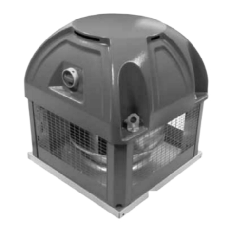
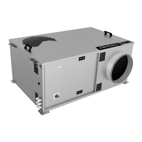
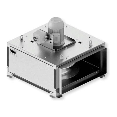
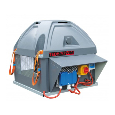
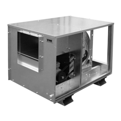
ViM JBRB ECOWATT PR User manual

NT00000603-JBRB-ECOWATT-PR-AN-191202
INSTRUCTION MANUAL
INSTALLATION | WIRING | COMMISSIONING | MAINTENANCE |
AFNOR CERTIFICATION
ISO 14001
Environnement
AFNOR CERTIFICATION
ISO 9001
Qualité
JBRB ECOWATT®PR
Collective residential building controlled mechanical ventilation
Tertiary premise ventilation 400°C 1/2hr C4 approved
Efectis certicate: EFR-16-002341

2/48 NT00000603-JBRB-ECOWATT-PR-AN-191202
CONTENTS
1. GENERAL INFORMATION ................................................................................................................ 3
1.1 Warnings .................................................................................................................................. 3
1.2 Safety instructions ................................................................................................................... 3
1.3 Reception - Storage.................................................................................................................. 3
1.4 Warranty .................................................................................................................................. 4
2. PRODUCT PRESENTATION.............................................................................................................. 4
2.1 Description................................................................................................................................ 4
2.2 Aeraulic curves ........................................................................................................................ 7
3. INSTALLATION .................................................................................................................................. 9
3.1 Dimensions and weight ............................................................................................................ 9
3.2 Handling ................................................................................................................................. 13
3.3 Choice of location................................................................................................................... 14
3.4 Ceiling-mounted installation ................................................................................................... 14
3.5 Accessories assembly............................................................................................................ 15
4. AERAULIC CONNECTION .............................................................................................................. 15
5. ELECTRICAL CONNECTION.......................................................................................................... 16
5.1 Prior precautions .................................................................................................................... 16
5.2 Electrical features .................................................................................................................. 16
5.3 Electrical connection of the local on-o switch ....................................................................... 16
5.4 Electrical connection of an external On / O control .............................................................. 17
5.5 Relay electrical connection - ventilation fault.......................................................................... 18
5.6 Electrical connection of optional TCOM remote control ......................................................... 19
5.7 Electrical connection of a 2V BCCA....................................................................................... 21
5.8 Electrical connection of a sensor (optional accessory)........................................................... 22
5.9 Electrical connection of a potentiometer (optional accessory) ............................................... 23
5.10 Electrical connection of a CENE power meter (optional accessory) ...................................... 24
6. COMMISSIONING............................................................................................................................ 24
6.1 Description of RMEC controller keys...................................................................................... 24
6.2 Calibration of built-in pressure sensors (COMPULSORY STEP)........................................... 24
6.3 Access levels.......................................................................................................................... 25
6.4 Setting of date and time.......................................................................................................... 26
6.5 Checking of active operating mode........................................................................................ 26
6.6 Local On/O control (factory setting)...................................................................................... 27
6.7 Selection of the main operating mode.................................................................................... 27
6.8 COP: Constant pressure ........................................................................................................ 28
6.9 CAV: Constant airow – 1 setting ........................................................................................... 28
6.10 CAV: Constant airow – 2 settings ......................................................................................... 29
6.11 VAV: Sensor-type analogue input airow control.................................................................... 30
6.12 VAV : Potentiometer-type analogue input airow control........................................................ 34
6.13 Clock function......................................................................................................................... 36
6.14 Power meter conguration...................................................................................................... 39
6.15 List of faults reported by the R1 contact output in ALARM function ...................................... 40
7. MENU AND MODBUS SETTINGS................................................................................................... 40
7.1 Modbus conguration ............................................................................................................. 40
7.2 Main settings / register tables................................................................................................. 42
8. MAINTENANCE ............................................................................................................................... 43
8.1 Prior precautions .................................................................................................................... 43
8.2 Maintenance frequency.......................................................................................................... 43
8.3 Access to electric fan.............................................................................................................. 43
8.4 Electric fan replacement......................................................................................................... 44
8.5 Spare parts............................................................................................................................. 46
9. WASTE MANAGEMENT.................................................................................................................. 46
9.1 Treatment of packaging and general industrial waste (GIW) ................................................. 46
9.2 Treatment of Professional WEEE........................................................................................... 46
3/48 NT00000603-JBRB-ECOWATT-PR-AN-191202
1. GENERAL INFORMATION
1.1 Warnings
This product has been manufactured according to rigorous technical rules of safety in conformity with EC
standards. The EC declaration may be downloaded from the Internet site (address given on the last page).
Before installing and using this product, carefully read these instructions, which contain important indi-
cations for your safety and the user’s safety during the installation, commissioning and maintenance of
this product. Once the installation is terminated, keep this manual handy nearby the machine for future
consultation.
This product must be installed (installation, connections, commissioning, maintenance) and all other inter-
ventions performed by a professional applying recognized good practice procedures, and respecting the
standards and safety regulations in force. The installation must be made in accordance with the prescrip-
tions indicated in the Electromagnetic Compatibility (EMC) and Low Voltage (LV) Directives.
We advise all people exposed to risks to scrupulously respect the accident prevention standards. The ma-
nufacturer may not be held liable for any human injury and/or material damage resulting from the non-res-
pect of the safety instructions or from a change made on the product.
JBRB ECOWATT®PR units are intended for controlled mechanical ventilation or air recycling applications
on tertiary premises and in collective residential buildings:
• Indoor or outdoor installation
• Environmental temperature: -20°C / +50°C
• Relative humidity: max. 95% without condensation
• Non-potentially-explosive atmosphere
• Low-salinity atmosphere, without corrosive chemical agents
1.2 Safety instructions
• Put on appropriate PPE (Personal Protective Equipment) before any work.
• Before installing the ventilation unit, make sure that the bracket and the location are strong enough
to bear the weight of the unit and any accessories.
• Do not open the access panels without having shut o the padlockable switch-disconnector included
in the unit.
• If work has to be carried out on the device, cut o the power supply on the main circuit breaker and
make sure that nobody can accidentally turn it back on.
• Make sure that moving parts are stationary.
• Check that the ventilation motor is not accessible via the connection brackets. (connection sheath
or protective shield).
Before starting, check the following points:
• Make sure that the device does not contain any foreign bodies.
• Check that all the components are mounted in their original positions.
• Check manually that the fans do not rub or get blocked.
• Check the connection of the earth electrode.
• Check that the access hatch is properly closed.
1.3 Reception - Storage
In case of short shipment, non-conformity, and/or total or partial damage to the products delivered, the
Buyer must, in accordance with article 133-3 of the French Commercial Code, add written reservations to
the carrier’s delivery slip and conrm them within 72 hours by registered letter with acknowledgement of
receipt with a duplicate for the seller. If the equipment is received without express reservation, the Buyer
has no subsequent recourse against us.
The product must be stored protected from weather, shocks and soiling due to splashing of any kind during
its transport from the supplier to the nal customer and on the site before installation.

4/48 NT00000603-JBRB-ECOWATT-PR-AN-191202
1.4 Warranty
The equipment is covered by a 12-month parts-only warranty from the billing date.
The seller undertakes to replace all parts or equipment that it recognises as malfunctioning, to the exclu-
sion of any damages or penalties such as operating losses, market injury and other non-material or indirect
damage.
The following are excluded from our warranty: faults connected with abnormal use or use not in accord-
ance with the recommendations in our manuals and instructions, defects found following normal wear and
tear, incidents caused by negligence, failure to monitor or maintain correctly, defects due to poor installa-
tion of the equipment or to poor storage conditions before installation.
In any event, the seller is not responsible for equipment that has been modied or repaired even if only
partially.
2. PRODUCT PRESENTATION
2.1 Description
The re certicate number certies that the JBRB ECOWATT®PR range complies with the order of 22
March 2004 of the French Interior Ministry.
400°C 1/2hr C4 APPROVED - Efectis certicate number: EFR-16-002341.
• Galvanised steel sheet casing equipped with 4 mounting feet (size 04 to 38) or 2 omega cross-piec-
es (sizes 48 to 92).
• High performance galvanised steel backward fan.
• INTZ: installed/wired lockable safety switch.
• ECM direct-current motor outside airow:
-04 to 22: IP44 class B single-phase 230V, 50Hz,
-30, 38, 48, 70, 82: IP54, class F, single-phase 230V, 50Hz,
-30, 38, 48, 70, 92: IP54, class F, three-phase 400V, 50Hz.
• RMEC controller:
-Constant pressure (COP), variable air volume (VAV), or constant air volume (CAV) operation.
-Factory-installed and -wired IP55 controller..
-Backlit LCD display, with front panel function buttons, optional remote control: clear displaying of measure-
ment (pressure, air volume) and selected setting.
• Connectionwithcircular bracket with class-Dairduct seals. Verticaldischargeversion delivered with-
out connection bracket (optional PAPV sealed at bracket for installation with self-drilling screws).
• Standard or insulated version (M0 re rating 25mm glass wool acoustic insulation).
• Cover equipped with handles, with tool-free removal.
• Horizontal or vertical discharge version.
• 3 available congurations: in-line, double inlet, modular: with elbow delivered with 1 stopper or 2 x
90° inlets.
Comment:
JBRB ECOWATT®PR models are equipped with an electronic-switching motor.
This motor is protected by:
- a built-in thermal protection on the motor winding,
- a thermistor built into the electronics.
These built-in motor protection systems have been tested and approved during re-resistance testing and
certied C4 400°C 1/2hr.

5/48 NT00000603-JBRB-ECOWATT-PR-AN-191202
Operating modes
COP mode: Constant pressure control
This operating mode is used to maintain constant pressure in the network over the fan’s entire used oper-
ating range. Network pressure drops (register opening/closing, dual-ow vents, etc.) modify the pressure
in the ventilation unit inlet plenum.
This pressure is measured by a sensor built into the RMEC controller.
This pressure measurement combined with a control loop means the RMEC can adjust fan speed to main-
tain constant pressure in the network.
The pressure setting can be adjusted using the RMEC controller control buttons.
Its operates 100%-automatically.
This operating mode is programmed by default on the unit when it leaves the factory with a pressure set
point of 140Pa.
0Airow (m3/h)
Pressure (Pa)
Regulated
pressure setpoint
Max airow curve
Regulated pressure curve
CAV mode: Constant air volume control
This operating mode is used to maintain constant airow in spite of changing network pressure drops (ex-
terior screen clogging, etc.). Up to 2 constant airow settings can be entered.
When CAV mode is selected, it is programmed to operate at a factory-pre-set airow of 70% of max. air-
ow. (See table § "6.9 CAV: Constant airow – 1 setting", page 28)
This value can be modied. Up to 2 airow set points can be entered, and in this case, a BCCA 2V 3-po-
sition switch will have to be used to switch from one airow to another. (See diagram § "5.4 Electrical
connection of an external On / O control", page 17)
Pressure (Pa)
Airow (m3/h)
Max airow curve
CAV Mode curve
Regulated airow setpoint
0

6/48 NT00000603-JBRB-ECOWATT-PR-AN-191202
VAV mode: Variable airow control according to analogue input
In VAV mode, the airow varies linearly, according to a setting signal (voltage 0-10V or current 4-20mA),
between a min. airow and a max. airow to be set in the RMEC controller. Each signal value corresponds
to an airow maintained constant irrespective of network pressure drops.
Principle:
Setpoint signal
Airow (m3/h)
Mini airow
setpoint
Max airow
setpoint
120
240
360
480
600
720
840
960
1080
1200
10%
0
20%
30%
40%
50%
60%
70%
80%
90%
100%
The signal can be transmitted by dierent types of sensors:
• SCO2 – CO2 sensor (0-10V or 4-20mA), in this case it will be displayed in ppm
• SHUR – Hygrometry sensor (0-10V or 4-20mA), in this case it will be displayed as a %
• STEM – Temperature sensor (0-10V or 4-20mA), in this case it will be displayed in °C
Or by a potentiometer:
• CVF
• REB ECOWATT®
The airow can be varied over part of the sensor’s measurement range or part of the potentiometer’s
voltage range (see § "6.11 VAV: Sensor-type analogue input airow control", page 30 and § "6.12 VAV :
Potentiometer-type analogue input airow control", page 34).

7/48 NT00000603-JBRB-ECOWATT-PR-AN-191202
2.2 Aeraulic curves
JBRB ECOWATT
®
PR 04 COP JBRB ECOWATT
®
PR 06 COP
100%
Qv (m3/h)
P(Pa)
stat
Δ
0
0
100
100
200
200
300
300 400 500
42
68
42
69
41
70
100%
P(Pa)
stat
Δ
0
100
200
300
400
0 100 200 300 400 500 600 700
Qv (m3/h)
42
75
43
77
45
79
Qv (m3/h)
0
0
20
40
60
80
100
100 200 300 400 500
100%
P(W)
abs
100%
0
0 100
50
100
150
200 300 400 500 600 700
Qv (m3/h)
P(W)
abs
JBRB ECOWATT
®
PR 10 COP JBRB ECOWATT
®
PR 22 COP
P(Pa)
stat
Δ
0
100
200
300
400
500
0
200 400
600 800 1000
1200
Qv (m3/h)
100%
41
73 38
71
37
71
100%
P(Pa)
stat
Δ
0
100
200
300
400
500
600
0 500 1000 1500 2000 2500
Qv (m3/h)
43
75 42
75
44
77
100%
Qv (m3/h)
0
0
50
100
150
200
200 400 600 800 1000
1200
P(W)
abs
100%
0 500 1000 1500 2000 2500
Qv (m3/h)
0
50
100
150
200
250
300
350
400
P(W)
abs

8/48 NT00000603-JBRB-ECOWATT-PR-AN-191202
JBRB ECOWATT
®
PR 30 COP JBRB ECOWATT
®
PR 38 COP
100%
Qv (m3/h)
P(Pa)
stat
Δ
0
100
200
300
400
500
600
700
0 500 1000 1500 2000 2500 3000 3500
47
77 45
76
48
78
P(Pa)
stat
Δ
0
100
200
300
400
500
600
0 500 1000 1500 2000 2500 3000 3500 4000 4500
100%
Qv (m3/h)
48
78 47
77
49
79
100%
0
100
200
300
400
500
600
700
800
Qv (m3/h)
P(W)
abs
0 500 1000 1500 2000 2500 3000 3500
100%
0 500 1000 1500 2000 2500 3000 3500 4000 4500
0
100
200
300
400
500
600
700
800
P(W)
abs
Qv (m3/h)
JBRB ECOWATT
®
PR 48 COP JBRB ECOWATT
®
PR 70 COP
P(Pa)
stat
Δ
0
100
200
300
400
500
0 1000 2000 3000 4000 5000 6000
Qv (m3/h)
100%
45
74 46
76
48
78
P(Pa)
stat
Δ
0
100
200
300
400
500
600
700
0 1000 2000 3000 4000 5000 6000 7000 8000
Qv (m3/h)
100%
51
79 51
79
53
81
0
100
200
300
400
500
600
700
800
P(W)
abs
Qv (m3/h)
100%
0 1000 2000 3000 4000 5000 6000
0
200
400
600
800
1000
1200
1400
P(W)
abs
Qv (m3/h)
100%
0 1000 2000 3000 4000 5000 6000 7000 8000

9/48 NT00000603-JBRB-ECOWATT-PR-AN-191202
JBRB ECOWATT
®
PR 82 COP JBRB ECOWATT
®
PR 92 COP
100%
P(Pa)
stat
Δ
0
100
200
300
400
500
600
0 1000 2000 3000 4000 5000 6000 7000 8000 9000
Qv (m3/h)
50
80 49
78
52
81
100%
Qv (m3/h)
P(Pa)
stat
Δ
00
300
600
900
1200
1500
1800
2100
2400
100
200
300
400
500
600
700
800
0 2000 4000 6000 8000 10000
P(W)
abs
52
82 50
81
52
83
100%
0 1000 2000 3000 4000 5000 6000 7000 8000 9000
0
200
400
600
800
1000
1200
1400
1600
P(W)
abs
Qv (m3/h)
100%
0 2000 4000 6000 8000 10000
P(W)
abs
Qv (m3/h)
0
200
400
600
800
1000
1200
1400
1600
1800
2000
3. INSTALLATION
3.1 Dimensions and weight
JBRB ECOWATT
®
PR 04 / 06 / 10 / 22 / 30 / 38
Horizontal discharge - L / M conguration
A
C
Ø D1
ØD1
B
C
I
J
B'
B
C
G
H
B'
E
F
Sense of the air
Sense of the air
Sense of the air
Only available
on modular version
Model A B B C* D1 E F G H I J Weight (kg)
JBRB ECOWATT
®
PR 04 627 523 533 320 160 568 502 157 175 157 161 22
JBRB ECOWATT
®
PR 06 627 523 533 320 200 568 502 157 175 157 161 22
JBRB ECOWATT
®
PR 10 627 566 583 421 250 569 544 207 185 207 186 26
JBRB ECOWATT
®
PR 22 767 683 701 511 355 709 661 252 237 252 239 45
JBRB ECOWATT
®
PR 30 1,019 820 873 568 400 892 797 267 271 267 271 64
JBRB ECOWATT
®
PR 38 1,153 938 971 631 500 1,036 907 306 331 306 331 78
* IS version: +27mm

10/48 NT00000603-JBRB-ECOWATT-PR-AN-191202
JBRB ECOWATT
®
PR 48 / 70 / 82 / 92
Horizontal discharge - L / M conguration
H
G
C
F
Ø D1
A
Ø D1
C
E
J
I
C
F
B'
B
Sense of the air
Sense of the air
Sense of the air
Only available
on modular version
Model A B B C* D1 E F G H I J Weight (kg)
JBRB ECOWATT
®
PR 48
1165 985 1,065 800 560 700 918 433 330 433 330 107
JBRB ECOWATT
®
PR 70
1,280 1,030 1,100 880 630 815 970 473 365 473 365 121
JBRB ECOWATT
®
PR 82
1,404 1,100 1,175 970 710 846 1,032 518 405 518 405 170
JBRB ECOWATT
®
PR 92
1,404 1,100 1175 970 710 846 1,032 518 405 518 405 171
* IS version: +27mm
JBRB ECOWATT
®
PR 10 / 22 / 38
Horizontal discharge - D conguration
B
C
I
J
B
C
ØD2
ØD2
A
C
ØD1
G
H
E
F
Sense of the air
Sense of the air
Sense of the air
Model A B C* D1 D2 E F G H I J Weight (kg)
JBRB ECOWATT
®
PR 10
815 603 421 250 200 777 544 194 161 207 186 28
JBRB ECOWATT
®
PR 22
1,048 720 511 355 315 998 661 239 219 252 239 45
JBRB ECOWATT
®
PR 38
1,468 1,024 631 500 400 1,396 908 306 281 306 331 83
* IS version: +27mm

11/48 NT00000603-JBRB-ECOWATT-PR-AN-191202
JBRB ECOWATT
®
PR 48 / 82 / 92
Horizontal discharge - D conguration
C
F
B
Ø D2
Ø D2
Ø D1
A
E
G
C
H
J
I
C
F
B
Sense of the air
Sense of the air
Sense of the air
Only available
on modular version
Model A B C* D1 D2 E F G H I J Weight (kg)
JBRB ECOWATT
®
PR 48
1,490 1,105 800 560 450 990 918 433 270 433 330 135
JBRB ECOWATT
®
PR 82
1,813 1,237 970 710 560 1,016 1,032 518 340 518 405 200
JBRB ECOWATT
®
PR 92
1,813 1,237 970 710 560 1,016 1,032 518 340 518 405 200
* IS version: +27mm
JBRB ECOWATT
®
PR 04 / 06 / 10 / 22 / 30 / 38
Vertical discharge - L / M conguration
A
C
Ø D1
B
C
B'
B
C
G
H
B'
F
I
E
J Sense of the air
Sense of the air
Only available
on modular version
Model A B B C* D1 E F G H I J Weight (kg)
JBRB ECOWATT
®
PR 04 609 523 533 320 160 568 502 157 175 130 165 22
JBRB ECOWATT
®
PR 06 609 523 533 320 200 568 502 157 175 130 165 22
JBRB ECOWATT
®
PR 10 616 566 583 421 250 569 544 207 185 166 198 26
JBRB ECOWATT
®
PR 22 756 683 701 511 355 709 661 252 237 236 271 45
JBRB ECOWATT
®
PR 30 973 820 873 565 400 892 797 267 271 248 286 64
JBRB ECOWATT
®
PR 38 1,106 938 971 637 500 1,036 907 306 331 315 350 78
* IS version: +27mm

12/48 NT00000603-JBRB-ECOWATT-PR-AN-191202
JBRB ECOWATT
®
PR 48 / 70 / 82 / 92
Vertical discharge - L / M conguration
H
G
F
A
Ø D1
EF
B'
B
J
I
Sense of the air
Sense of the air
Only available
on modular version
Model A B B C* D1 E F G H I J Weight (kg)
JBRB ECOWATT
®
PR 48 1,119 985 1,065 800 560 700 918 433 330 320 340 107
JBRB ECOWATT
®
PR 70 1,234 1,030 1,100 880 630 815 970 473 365 370 375 121
JBRB ECOWATT
®
PR 82 1,358 1,100 1,175 970 710 846 1,032 518 405 482 415 170
JBRB ECOWATT
®
PR 92 1,358 1,100 1,175 970 710 846 1,032 518 405 482 415 171
* IS version: +27mm
JBRB ECOWATT
®
PR 10 / 22 / 38
Vertical discharge - D conguration
B
C
B
C
ØD2
ØD2
A
C
G
H
E
F
I
J Sense of the air
Sense of the air
Sense of the air
Model A B C* D1 D2 E F G H I J Weight (kg)
JBRB ECOWATT
®
PR 10 804 603 421 250 200 777 544 194 161 166 198 28
JBRB ECOWATT
®
PR 22 1,037 720 511 355 315 998 661 239 219 236 271 45
JBRB ECOWATT
®
PR 38 1,426 1,025 637 500 400 1,396 909 306 281 315 350 83
* IS version: +27mm

13/48 NT00000603-JBRB-ECOWATT-PR-AN-191202
JBRB ECOWATT
®
PR 48 / 82 / 92
Vertical discharge - D conguration
C
F
B
Ø D2
Ø D2
C
A
E
G
H
C
F
L
J
I
Sense of the air
Sense of the air
Sense of the air
Model A B C* D1 D2 E F G H I J Weight (kg)
JBRB ECOWATT
®
PR 48 1,444 1,105 800 560 450 990 918 433 270 320 340 135
JBRB ECOWATT
®
PR 82 1,767 1,237 970 710 560 1,016 1,032 518 340 482 415 200
JBRB ECOWATT
®
PR 92 1,767 1,237 970 710 560 1,016 1,032 518 340 482 415 200
* IS version: +27mm
3.2 Handling
N.B.: Do not use plastic handles to move the unit. These handles are only to
open the unit cover.
JBRB ECOWATT
®
PR 04 to 38 JBRB ECOWATT
®
PR 48 to 92

14/48 NT00000603-JBRB-ECOWATT-PR-AN-191202
3.3 Choice of location
JBRB ECOWATT
®
PR 04 to 38 JBRB ECOWATT
®
PR 48 to 92
C
C
C
C
C
C
Leave the height of the unit above the unit and on the door side for device commissioning and mainte-
nance.
3.4 Ceiling-mounted installation
JBRB ECOWATT
®
PR 04 to 38 Ceiling-mounted installation
100
C
C
JBRB ECOWATT®PR Sigfox size 04 to 38 units can
be installed with the cover facing downwards.
• Air space of at least 100mm must be main-
tained between the unit and the horizontal sur-
face on which it is set up.
• Horizontal discharge: unconditionally author-
ised.
• Vertical discharge: authorised if connected to
an aeraulic network.
• The unit fastening mode must be sucient to
ensure it is held well in place in case of re.

15/48 NT00000603-JBRB-ECOWATT-PR-AN-191202
3.5 Accessories assembly
Circular connection to discharge
Fasten the sealed at bracket using 6 self-drilling screws (not supplied).
For a unit not connected to discharge, add a vent cowl (CP) to enable 360° exhaust air outlet around
the vertical discharge axis. According to the NF DTU 68.3 P 1-1-1 standard, the CP makes it possible to
eliminate the eects of the wind and not add 20Pa of additional pressure drop.
4. AERAULIC CONNECTION
The unit must be fastened to a very at surface, using the holes drilled in the mounting feet or the omega
bars provided for this purpose. Mounting on anti-vibration supports and connection with exible connectors
are recommended.
L
In-line
M
Modular
D
Double inlet
90° elbow 90° double inlet
Horizontal
discharge
En ligne
L
Double aspiration
D
Modulable coudé à 90° /
double aspiration à 90°
M
Orientation
rejet
horizontal
Orientation
rejet
vertical
En ligne
L
Double aspiration
D
Modulable coudé à 90° /
double aspiration à 90°
M
Orientation
rejet
horizontal
Orientation
rejet
vertical
En ligne
L
Double aspiration
D
Modulable coudé à 90° /
double aspiration à 90°
M
Orientation
rejet
horizontal
Orientation
rejet
vertical
En ligne
L
Double aspiration
D
Modulable coudé à 90° /
double aspiration à 90°
M
Orientation
rejet
horizontal
Orientation
rejet
vertical
En ligne
L
Double aspiration
D
Modulable coudé à 90° /
double aspiration à 90°
M
Orientation
rejet
horizontal
Orientation
rejet
vertical
Vertical
discharge
En ligne
L
Double aspiration
D
Modulable coudé à 90° /
double aspiration à 90°
M
Orientation
rejet
horizontal
Orientation
rejet
vertical
En ligne
L
Double aspiration
D
Modulable coudé à 90° /
double aspiration à 90°
M
Orientation
rejet
horizontal
Orientation
rejet
vertical
En ligne
L
Double aspiration
D
Modulable coudé à 90° /
double aspiration à 90°
M
Orientation
rejet
horizontal
Orientation
rejet
vertical
En ligne
L
Double aspiration
D
Modulable coudé à 90° /
double aspiration à 90°
M
Orientation
rejet
horizontal
Orientation
rejet
vertical
En ligne
L
Double aspiration
D
Modulable coudé à 90° /
double aspiration à 90°
M
Orientation
rejet
horizontal
Orientation
rejet
vertical
The setup of this unit’s aeraulic system and its network must meet the technical conditions dened in the
NF DTU 68-3 standard in case of installation of collective controlled mechanical ventilation.
Connection diameters:
Model L, M, D discharge L, M inlet D inlet
JBRB ECOWATT
®
PR 04 160 160 -
JBRB ECOWATT
®
PR 06 200 200 -
JBRB ECOWATT
®
PR 10 250 250 200
JBRB ECOWATT
®
PR 22 355 355 315
JBRB ECOWATT
®
PR 30 400 400 -
JBRB ECOWATT
®
PR 38 500 500 400
JBRB ECOWATT
®
PR 48 560 560 450
JBRB ECOWATT
®
PR 70 630 630 -
JBRB ECOWATT
®
PR 82 710 710 560
JBRB ECOWATT
®
PR 92 710 710 560

16/48 NT00000603-JBRB-ECOWATT-PR-AN-191202
5. ELECTRICAL CONNECTION
5.1 Prior precautions
Models 30 to 92:
This electronic-switching motor cannot be powered directly by mains power, on pain of destruction. Its
power must be supplied by the controller. The device must be turned on and o via the RMEC local con-
trol (wiring, see §"6.6 Local On/O control (factory setting)", page 27) or via the BCCA external On/O
control (wiring, see "5.4 Electrical connection of an external On / O control", page 17). Do not turn o
the device by directly shutting o the controller’s power supply via the INTZ or shutting o the mains power
supply.
Shut o and disconnect the power supply before carrying out any work.
In case of work on the fan, the local on-o switch dened according to IEC947-3/695-2-1 must be open
and locked in this position (according to NF C 15-100).
5.2 Electrical features
Size Single-phase 230V Three-phase 400V
Input power
(kW) Max. C.
(A) Input power
(kW) Max. C.
(A)
JBRB ECOWATT
®
PR 04 0.07 0.7 - -
JBRB ECOWATT
®
PR 06 0.13 1.0 - -
JBRB ECOWATT
®
PR 10 0.15 1.2 - -
JBRB ECOWATT
®
PR 22 0.35 1.6 - -
JBRB ECOWATT
®
PR 30 0.60 2.6 0.60 1.2
JBRB ECOWATT
®
PR 38 0.70 3.1 0.70 1.3
JBRB ECOWATT
®
PR 48 0.72 3.1 0.72 1.5
JBRB ECOWATT
®
PR 70 1.24 5.4 1.24 2.6
JBRB ECOWATT
®
PR 82 1.40 6.0 - -
JBRB ECOWATT
®
PR 92 - - 1.70 3.5
5.3 Electrical connection of the local on-o switch
The switch is used to isolate the device from the power supply in case of maintenance, or to turn the device
on/o.
JBRB ECOWATT
®
PR 04 to 22 Single-phase
NL

17/48 NT00000603-JBRB-ECOWATT-PR-AN-191202
JBRB ECOWATT
®
PR 30 to 82 Single-phase
NL
JBRB ECOWATT
®
PR 30 to 92 Three-phase
L1 L2 L3
To access the on-o switch terminals, unscrew the door’s 2 M8 screws using a 13mm spanner.
Add a cable gland to the power cable and connect it to the on-o switch terminals.
5.4 Electrical connection of an external On / O control
The RMEC controller has a local On-O control: an external On-O control can be connected to terminals
DI1 and GND. The external “on” request takes priority over the local “o” request.
L
N
GND
B
AMODBUS
DAT
12V
GND
AI1
GND
15V
AI2
GND
10V
DI1
DI2
GND
DI3
GND
DI4
AO1
GND
AO2
ANALOG INPUTS
Alim
230V
REMOTE CONTROL
POWER SUPPLY OUTPUT
POWER SUPPLY OUTPUT
DIGITAL INPUTS
ANALOG OUTPUT
RELAY
PRESSURE SENSORS
PA PB
R1A
R2A
R1B
R2B
–+–+
On / O Contact
BCCA

18/48 NT00000603-JBRB-ECOWATT-PR-AN-191202
5.5 Relay electrical connection - ventilation fault
5.5.1 Relay electrical connection - Model 04 to 22
L
N
GND
B
AMODBUS
DAT
12V
GND
AI1
GND
15V
AI2
GND
10V
DI1
DI2
GND
DI3
GND
DI4
AO1
GND
AO2
ANALOG INPUTS
Alim
230V
400V
power supply
REMOTE CONTROL
POWER SUPPLY OUTPUTS
DIGITAL INPUTS
ANALOG OUTPUTS
RELAYS
PRESSURE SENSORS
PA PB
R1A
R2A
R1B
R2B
––+
L1
L2
Ventilation fault wiring
Open contact - Stop of the fan
5.5.2 Relay electrical connection - Model 30 to 82 single-phase
1234
Ventilation fault wiring
Open contact - Stop of the fan
5678910 11 12 13 14 15 16 17 18 19 20 21 22 23 24 25 26 27
+24V
Fire
+24V
Start/Stop
Speed-Output
GND
+24V
GND
An2
+5V
Pot
GND
An1
NO
COM
NC
Relay fault
N
L
Compacto
A
B
U
V
W
Unit status Relay status
“Normal” operation NO
Power supply shut o NC
On/O contact - The wheel is stationary but the conductor is powered up NC
Phase loss - In case of phase loss, the wheel may continue to turn NC

19/48 NT00000603-JBRB-ECOWATT-PR-AN-191202
5.5.3 Relay electrical connection - Model 30 to 92 three-phase
12345678910 11 12 13 14 15 16 17 18 19
+24V
Fire
+24V
Start/Stop
Speed-Output
GND
+24V
GND
An2
+10V
GND
An1
NO
COM
NC
Relay fault
Ventilation fault wiring
Open contact - Stop of the fan
Invento
A
B
PE
U
V
W
PE
L1
L2
L3
Unit status Relay status
“Normal” operation NO
Power supply shut o NC
On/O contact - The wheel is stationary but the conductor is powered up NC
Phase loss - In case of phase loss, the wheel may continue to turn NC check-list
5.6 Electrical connection of optional TCOM remote control
The remote control covers all the RMEC front panel functions:
• It includes a 20-alphanumeric character, 2-line backlit LCD display, and a navigation button in the
Menu. 2 green/red LEDs indicate the communication activity between the RMEC and the remote
control.
Protection index (PI): 21.
Operating environment:
• Temperature 0°C to + 40°C without condensation.
• 30 to 80% relative humidity.
It can be connected to the RMEC in two ways according to use:
Temporary connection:
Standard application case = for conguration of the product, when the RMEC display is not clearly visible (e.g.
installation in suspended ceiling).
• Shut o the RMEC power supply.
• Removethewaterproof stopperfromthe RMECfrontpanel to accessthe jack socket TheRMEC’s
protection index then switches from IP55 to IP21.
• A 1m-long jack cable is supplied with the remote control: clip its HE13 socket to the back of the re-
mote control, see plan below, and insert its jack plug into the RMEC’s jack socket.
• Power the RMEC back up.
• Congure the RMEC using the remote control.
• Once you’ve nished, shut o the RMEC’s power supply.
• Unplug the jack plug from the RMEC.
• Replace the RMEC front panel waterproof stopper to restore its protection index to IP55.
• Power the RMEC back up.
N.B.: plugging the remote control in or unplugging it from the RMEC without shutting o its power supply caus-
es a temporary short-circuit, which resets the microcontroller. This does not present any physical risk for the
worker, but should be avoided because it strains the electronic components.

20/48 NT00000603-JBRB-ECOWATT-PR-AN-191202
Permanent connection:
• Required when permanently installed on the system.
• An extra HE13 quick connector is supplied with the remote control (self-crimping Comatel 478 se-
ries).
• It must be connected with a 0.2mm²-section (AWG 22 or 24 gauge), 3-conductor cable, maximum
length: 100 metres.
• Insert the 3 conductors into the connector, then press hard to crimp them (by hand or with precaution
using multiple slip joint pliers). Check that it is held in place.
• Clip the connector to the back of the remote control, see plan below.
• RMEC side: add one of the cable glands supplied to the cable. Then connect it to the “DAT / 12V /
GND” terminals. Finally, tighten the cable gland to ensure the cable is securely fastened and main-
tain the RMEC’s IP55 protection index.
• Fasten the remote control to the wall (may be built-in, to be handled with precaution), in an environ-
ment compatible with its IP21 protection index.
L
N
GND
B
AMODBUS
DAT
12V
GND
AI1
GND
15V
AI2
GND
10V
DI1
DI2
GND
DI3
GND
DI4
AO1
GND
AO2
ANALOG INPUTS
230V
power
supply
REMOTE CONTROL
POWER SUPPLY OUTPUTS
POWER SUPPLY OUT PUTS
DIGITAL INPUTS
ANALOG OUTPUTS
RELAYS
PRESSURE SENSORS
PA PB
R1A
R2A
R1B
R2B
–+–+
Remote control connector
for a permanent wiring
S
–
+
N.B.: 2 remote controls may be connected simultaneously: one permanently connected, the other temporarily.
To limit the maximum input voltage, the remote control display backlighting turns o automatically when no
buttons are pressed for 1 minute.
This manual suits for next models
10
Table of contents
Other ViM Fan manuals

ViM
ViM KUBAIR F400 ECOWATT User manual

ViM
ViM KUBAIR F400 ECOWATT User manual

ViM
ViM TEDH F400 User manual

ViM
ViM KUBAIR F400 ECOWATT CC User manual

ViM
ViM TEDH F400 User manual

ViM
ViM TEDH F400 User manual

ViM
ViM JBRB ECOWATT PR VCHV User manual

ViM
ViM KDTA-R F400 User manual

ViM
ViM KUBAIR F400 User manual

ViM
ViM TEDH F400 User manual
Popular Fan manuals by other brands

Brock
Brock AX12 troubleshooting guide

Home Decorators Collection
Home Decorators Collection N383B-MBK Use and care guide

Brandson
Brandson 303830 user manual

Craftsman
Craftsman Brilliante BRC52 - 4 Light installation guide

LMF Clima
LMF Clima HRH 05 Installation, operation and maintenance manual

unicraft
unicraft MV Series operating instructions