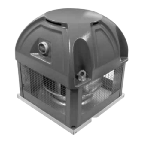
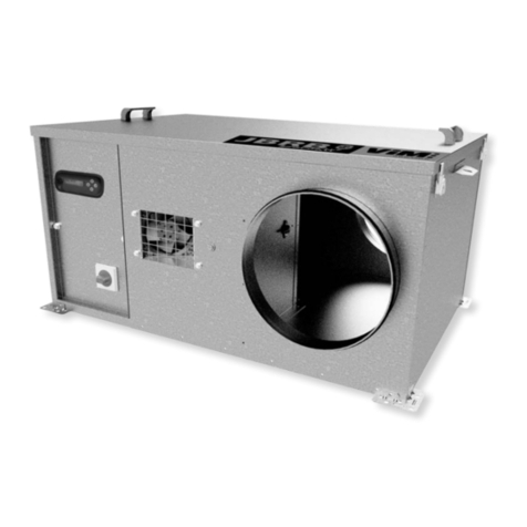
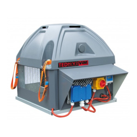
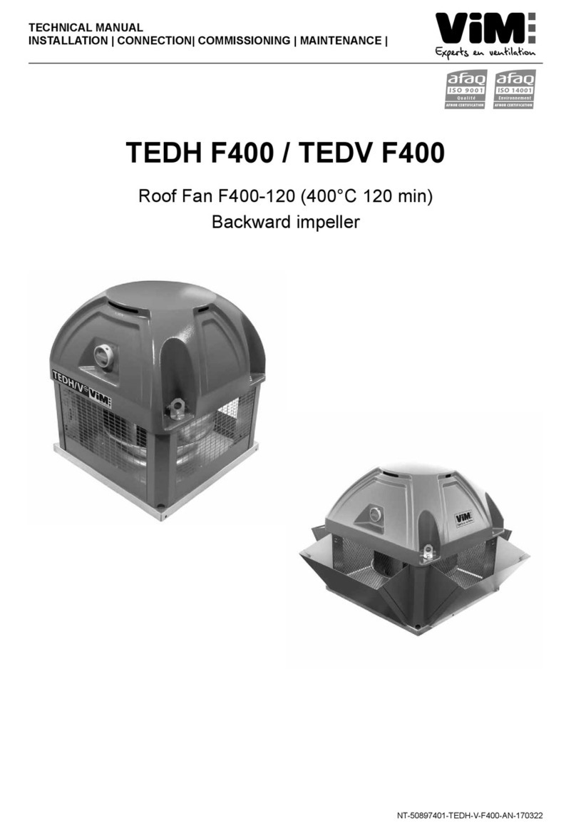
ViM TEDH F400 User manual

1/60 NT00000658-TEDH-V-F400-ECOWATT-AN-210609
ENGLISH
AFNOR CERTIFICATION
ISO 14001
Environnement
AFNOR CERTIFICATION
ISO 9001
Qualité
TECHNICAL MANUAL
INSTALLATION | CONNECTION| COMMISSIONING | MAINTENANCE |
TEDH F400 ECOWATT®
TEDV F400 ECOWATT®
Roof Fan F400-120 (400°C 120 min)
EC Motor
VENTIDRIVE Controller

2/60 NT00000658-TEDH-V-F400-ECOWATT-AN-210609
SUMMARY
1. GENERAL........................................................................................................................................... 3
1.1 Disclaimers............................................................................................................................... 3
1.2 Safety instructions.................................................................................................................... 3
1.3 Acceptance – Storage.............................................................................................................. 3
1.4 Warranty................................................................................................................................... 4
2. PRODUCT PRESENTATION.............................................................................................................. 4
3. INSTALLATION .................................................................................................................................. 5
3.1 Dimensions and weights........................................................................................................... 5
3.2 Handling ................................................................................................................................... 6
3.3 Summary charts of assembly and accessories........................................................................ 7
3.4 Removing the caps................................................................................................................. 13
3.5 Mounting the roof fan.............................................................................................................. 13
3.6 Mountingtherooffandeectors............................................................................................. 14
4. ELECTRICAL CONNECTION.......................................................................................................... 15
4.1 Preliminary precautions.......................................................................................................... 15
4.2 Electrical characteristics......................................................................................................... 16
4.3 Wiring of INTZ safety switch................................................................................................... 17
5. COMMISSIONING AND CONFIGURATION OF ONE-PHASE CONTROLLERS
SIZES 355/400/450........................................................................................................................... 19
5.1 Presentation of the VENTIDRIVE single-phase controller...................................................... 19
5.2 Modbus connection - Connection to a BMS........................................................................... 21
5.3 Supported Modbus commands............................................................................................... 22
5.4 Relay operation ...................................................................................................................... 29
5.5 Smoke extraction operation.................................................................................................... 30
5.6 VAVvariableairowmode...................................................................................................... 31
5.7 CAVconstantairowmode .................................................................................................... 40
5.8 COP constant pressure mode................................................................................................ 41
6. COMMISSIONING AND CONFIGURATION OF THREE-PHASES CONTROLLERS
SIZES 500/630/710........................................................................................................................... 43
6.1 Presentation of the INVENTO three-phases controller........................................................... 43
6.2 Modbus connection - Connection to a BMS........................................................................... 45
6.3 Relay operation ...................................................................................................................... 48
6.4 Smoke extraction operation.................................................................................................... 48
6.5 VAVvariableairowmode...................................................................................................... 49
6.6 CAVconstantairowmode .................................................................................................... 51
6.7 COP constant pressure mode................................................................................................ 54
7. MAINTENANCE................................................................................................................................ 57
7.1 Maintenance frequency.......................................................................................................... 57
7.2 Spare parts............................................................................................................................. 58
8. WASTE MANAGEMENT.................................................................................................................. 59
8.1 Treatment of Packagings and non dangerous wastes ........................................................... 59
8.2 Treatment of a Professional WEEE........................................................................................ 59

3/60 NT00000658-TEDH-V-F400-ECOWATT-AN-210609
1. GENERAL
1.1 Disclaimers
This product has been manufactured according to rigorous technical rules of safety in conformity with EC
standards. The EC declaration may be downloaded from the Internet site (address given on the last page).
Before installing and using this product, carefully read these instructions, which contain important indica-
tions for your safety and the user’s safety during the installation, commissioning and maintenance of this
product. Once the installation is achieved, keep this manual handy nearby the machine for future consul-
tation.
This product must be installed (installation, connections, commissioning, maintenance) and all other inter-
ventions performed by a professional applying recognized good practice procedures, and respecting the
standards and safety regulations in force. The installation must be made in accordance with the prescrip-
tions indicated in the Electromagnetic Compatibility (EMC) and Low Voltage (LV) Directives.
We advise all people exposed to risks to scrupulously respect the accident prevention standards. The ma-
nufacturer may not be held liable for any human injury and/or material damage resulting from the non-res-
pect of the safety instructions or from a change made on the product.
Smoke extract unit TEDH/V F400 ECOWATT®are intended for smoke extraction and ventilation applica-
tions in residential buildings, tertiary buildings, industrial buildings and professional kitchens:
• Outdoor installation
• Environmental temperature range:
-One-phase unit: -40°C / +50°C
-Three-phases unit: -10°C / +45°C. If the unit remains turned on, minimum temperature is -20°C.
• Max temperature of extracted air in permanent operation: 120°C
• Relative humidity: min 5% - max 90% non-condensing
• Atmosphere not potentially explosive
• Low salinity atmosphere, with no corrosive chemical agents
1.2 Safety instructions
• Wear suitable PPE (Personal Protective Equipment) before any intervention.
• Before installing the roof fan and its accessories, make sure that the support and the location are
sucientlyresistanttowithstandtheunit’sweightandtheaccessories,ifany.
• Donotremovemeshgrillestoaccesstheimpellerbeforecuttingotheelectricpowersupplywith
the safety switch.
• Iftheworkistobedoneinsidethedevice,cutotheelectricpowersupplywiththemaincircuitbrea-
ker and make sure that nobody can accidentally switch it back on.
• Make sure that moving parts are stopped.
• Make sure that the impeller is not accessible from connection tappings (connection duct or mesh
protection).
Before starting, check the following points:
• Make sure that the device does not contain any foreign body.
• Make sure that all the components are attached to their original locations.
• Check manually that the impeller does not rub or is not blocked.
• Make sure that the mesh protection are in place.
• Make sure that the ground connection is connected.

4/60 NT00000658-TEDH-V-F400-ECOWATT-AN-210609
1.3 Acceptance – Storage
In case of missing items or delivery of non conforming, partially or totally damaged products, the Buyer
shall make, in accordance with article 133-3 of the French Commercial Code, reservations in writing on the
transporterreceiptandconrmthemwithinseventy-two(72)hoursbyregisteredletteralongwithacopy
addressed to the seller. Should the Buyer fail to make reservations when he receives the equipment, he
will not be allowed to make any future claim against us.
The product must be stored protected from the weather, shocks and dirt due to splashings or splatterings
of any kind during transport from the supplier to the end customer, and onto the worksite before installation.
1.4 Warranty
The equipment is guaranteed for 24 months from the invoice date. The warranty is limited to the replace-
ment of parts or equipment whose operation is recognized as defective by maker, excluding any com-
pensation or penalties. The costs of labor, removal and rest, travel related to the replacement are the
responsibility of the Customer. Excluded from our warranty are defects linked to abnormal use or not in
accordance with the recommendations in our instructions, defects observed as a result of normal wear
and tear, incidents caused by negligence, lack of monitoring or maintenance, defects due to incorrect
installation of devices or poor storage conditions prior to assembly.
In any case, maker is not responsible for transformed material, even partially repaired.
2. PRODUCT PRESENTATION
Range
• Airowfrom200upto24000m3/h.
• 6 sizes : 355 / 400 / 450 / 500 / 630 / 710
Certication
ECCerticateF400-120No.1812-CPR-1085,accordingtoEuropeanStandardNFEN12101-3.
Approved F400 120 (400°C 120min).
Construction
• TEDH F400 ECOWATT®: horizontal discharge through 2 or 3 sides.
• TEDV F400 ECOWATT®: vertical discharge through 2 or 3 sides.
• Built-indisplay(optiononvariableairowVAVorconstantpressurecontrolledCOPversions)dis-
playstheairoworpressuredependingontheunitmodel.
• High performance backward fan in galvanised steel.
• Convergent/divergent inlet cones.
• Galvanised steel motor plate, frame and motor support.
• 4 lifting lugs.
• Protective grid in pre-painted galvanised steel sheet, grey 7024. Meshes in accordance with NF EN
ISO 12499.
• Arm covers and protection guards in pre-painted sheet steel, grey RAL 7024.
• Cap in ABS PMMA grey RAL 7024.
• Vertical rejection version: addition of3deectorsinRAL 7024 pre-painted sheet metal delivered
assembled in the factory (model TEDV F400 ECOWATT®) or available as a kit for on-site installation
(KRVT).
Motor
• ECOWATT®motor, F class, 3 phases with remote IP55 controller :
-VENTIDRIVE controller 1 phase power supply 230V 50/60Hz controller input for sizes 355 up to 450.
-INVENTO controller 3 phases power supply 400V 50/60Hz controller input for sizes 500 up to 710.
• Thermalprotectionttedwithinthecontroller.
Controller supplied as an accessory for TEDH-V F400 ECOWATT®single-phase
• ETDZ A: Stand-alone remote touch ModBus control for controlling 1 unit.
• ETDZ R: Network touch remote ModBus control for controlling 2 to 32 units in a network.

5/60 NT00000658-TEDH-V-F400-ECOWATT-AN-210609
3. INSTALLATION
3.1 Dimensions and weights
TEDH F400 ECOWATT
®
TEDV F400 ECOWATT
®
F
CH
B
A
Fixation E
Ø D
B
CV
Fixation E
Ø D
A
F
Model A* B* CH* CV* D* E* F* Weight H (kg) Weight V (kg)
355
540 570 754 901 289,1 450 30 34 38
400
540 609 754 926 325,8 450 30 44 49
450
660 684 864 1051 366,5 570 30 57 63
500
660 700 867 1070 407,3 570 30 83 94
630
800 805 1045 1279 513,1 668 30 106 116
710
946 1089 1223 1489 577,9 830 40 165 179
* Dimensions in mm

6/60 NT00000658-TEDH-V-F400-ECOWATT-AN-210609
3.2 Handling
2 x B
To avoid injurying people or damaging the equipment, use handling devices in conformity and in good
condition. The roof fan must be lifted with 4 lifting lugs.
Use slings with lengths greater than or equal to twice roof fan height. The caps must be removed before
slinging (see § "3.4 Removing the caps"). Make sure that the slings do not rub against the dome. If in
doubt, remove the dome to avoid damaging it.
Standardised 400mm long slings are supplied with the products to easily handle the roof fan units.
WARNING: Do not leave the slings on the product once it is installed.
VIM shall be relieved of any responsibility in case these slings are not properly used.
WARNING: Do not lift the product by holding it by the plastic cover cap.

7/60 NT00000658-TEDH-V-F400-ECOWATT-AN-210609
3.3 Summary charts of assembly and accessories
TCDZ01
TCDZ05*
TCDZ03
TCDZ03
TEDH F400 ECOWATT
®
TEDV F400 ECOWATT
®
TDCZ06
SIL
POPM KRVT
(TEDH) TCDZ 14
(TEDV) TCDZ 15
(TEDH)
TCDZ 04 TCDZ 07 TCDZ 02 TCDZ 09
ou ou
ou
ou
ou ou
TCDZ08
* : Some adaptation plate diameters are not compatible with the following accessories: TCDZ 02, 04, 07 and 08 (see § "3.3.4
Adaptation plate : TCDZ 05", page 9).

8/60 NT00000658-TEDH-V-F400-ECOWATT-AN-210609
3.3.1 Standard support: TCDZ 01
Thisassemblydoesnotallowusinganenergysaveaporanadaptationplate.Makesurethattheduct
can withstand the roof fan weight.
B
C
325mm mini
A
• Install the 4 angle brackets B and the 2 hose
clamps C on the duct.
• Install the seal A on the duct’s free edge.
• Put the roof fan on the duct by centring it cor-
rectly.
• AdjustandxtheanglebracketsBontheas-
sembly.
• Tighten the 2 hose clamps C.
Unit size Min duc Ø
(mm) Max duc Ø
(mm) Weight
(kg)
355
315 355 3
400
355 355 3
3.3.2 Embedding frame: TCDZ 02
A mini
Seal the frame in the concrete support and make
sure that the sealing pads are embedded in the
concrete.
E
G
S
3.3.3 Energy saver ap : TCDZ 03
Mounttheenergysaverapinsidetheinsertsundertherooffan.Thisisincompatiblewiththeuseof
adaptation plates TCDZ 05 and the standard support TCDZ 01. Before mounting the roof fan, make sure
theapsswingfreely.Takeintoaccount50Papressuredrop.
E
G
M
K
Unit size Accessory
size E* G* M* K* Weight
(kg)
355/400
2 450 478 145 400 5
450/500
3 570 598 170 490 6
630
4 668 698 170 605 8
710
5 830 866 190 730 11
* Dimensions in mm
Unit size Accessory
size A* E* G* S* Weight
(kg)
355/400
2 70 450 478 30 2,5
450/500
3 70 570 598 40 4
630
4 70 668 698 40 4,5
710
5 70 830 866 40 6
* Dimensions in mm

9/60 NT00000658-TEDH-V-F400-ECOWATT-AN-210609
3.3.4 Adaptation plate : TCDZ 05
G
E
ØD
T
The adaptation plate allows connecting roof fan
to a circular duct. Since it is designed to make the
air connection, it is not supposed to withstand roof
fan weight. This is incompatible with the use of the
energysaverapTCDZ03andtheroofadapter
with sound attenuator TCDZ 09.
Model Accessory
size Dimensions (mm) Weight
(kg)
G E T ØD
355/400
Size 2 478 450 50 315 1,8
355/400
Size 2 478 450 65 355 1,5
355/400
Size 2 478 450 80 400 1,2
355/400
Size 2 478 450 80 450* 0,8
450/500
Size 3 598 570 80 400 3,6
450/500
Size 3 598 570 80 450 3,1
450/500
Size 3 598 570 80 500 2,5
450/500
Size 3 598 570 80 560* 1,7
630
Size 4 698 668 80 450 5,1
630
Size 4 698 668 80 500 4,5
630
Size 4 698 668 80 560 3,7
630
Size 4 698 668 90 630 2,7
710
Size 5 866 830 80 560 11,8
710
Size 5 866 830 90 630 10,3
710
Size 5 866 830 120 710 8,3
*
These adaptation plates cannot be mounted in the following accessories: TCDZ 02, 04, 07 and 08.
3.3.5 Tipping-up kit: TCDZ 06
This kit allows safely swinging the roof fan for cleaning operations. It is placed on the embedding frames
TCDZ 02, roof adapters TCDZ 04, TCDZ 07 or TCDZ 09 and can be placed on top of the adaptation
platesTCDZ05ortheenergysaverapTCDZ03.
hinge
lug piece
Safety bar
Chain
• Make sure that there is a sucient height
between the oor and the roof fan plate so
that the roof fan does not touch the oor/
ground when it swings.
• Make sure that the power cables lengths are
suciently long to allow swinging the ma-
chine without stressing them.
Make sure that the support is correctly attached
totheoorandcanwithstandtheshearingstress
due to the swinging of the roof fan :
• Positionthehingeandfastenitwiththe2at
nuts supplied.
• Tie up a chain extremity to the lug piece with
the HM18x16 bolt provided.
• Position the undrilled side of the safety bar
inthelugpieceandttheassemblyonthe
support.
• Fastenthelugpiecewiththe2atnutssup-
plied.

10/60 NT00000658-TEDH-V-F400-ECOWATT-AN-210609
Foam
seal
• Glue the foam seal on the support.
• Position the roof fan on the kit (pay particular
attention to the plate’s direction).
• Screw the 2 HM8x20 screws in the hinge’s
crimped nuts.
• Tie up the free chain extremity to the roof fan
plate with an HM8x16 bolt supplied.
• Lift the roof fan and immediately install the
safety bar and lock it with the safety pin.
• Glue the instruction label near the safety bar.
The roof fan must be attached to its support when
commissioned.
3.3.6 Sound attenuators : SILS
Take into account an 80 Pa pressure drop.
A
E
E
G
Ø19
Ø12
J
Unit size Accessory
size A* J* E* G* Weight
(kg)
355/400
2 540 630 450 478 23
450/500
3 660 700 570 598 37
630
4 800 700 668 698 45
710
5 930 700 830 866 65
*Dimensions in mm

11/60 NT00000658-TEDH-V-F400-ECOWATT-AN-210609
3.3.7 Horizontal and inclined roof adapters : TCDZ 04, TCDZ 07 ou 09
ItispossibletoassociateanenergysaveapTCDZ03oranadaptationplateTCDZ05(exceptforTCDZ
09) placed inside the insert.
For roof fan with acoustic straight insert (TCDZ 09), take into account a 80Pa pressure drop.
TCDZ 04 TCDZ 07 TCDZ 09
100
G
N
E
R
E
G
150
100
100
α
E
G
N
800
100
3.3.8 Roof adapter heightener (TCDZ 08)
Allows to rise the roof fan by 200mm, allows to insert an adaptation plate TCDZ 05 between roof fan
andtheenergysaverapTCDZ03,ortomountanenergysaverapTCDZ03onanembeddingframe
TCDZ 02.
TCDZ 04
TCDZ 05
TCDZ 03 TCDZ 08
200
G
E
Unit size Accessory
size E* G* N* R* Weight (kg)
TCDZ 04 TCDZ 07
30° angle TCDZ 09
355/400
2 450 478 678 300/500/700 11/15,5/20 11,2 34
450/500
3 570 598 798 300/500/700 13,5/19/25 14,8 51
630
4 668 698 898 300/500/700 20,5/29,5/38 24,2 65,5
710
5 830 866 1066 300/500/700 25,5/37/48 32,4 90,5
*Dimensions in mm
Unit size Accessory
size E* G* Weight
(kg)
355/400
2 450 478 6,2
450/500
3 570 598 10,5
*Dimensions in mm
Unit size Accessory
size E* G* Weight
(kg)
630
4 668 698 12,2
710
5 830 866 15
*Dimensions en mm

12/60 NT00000658-TEDH-V-F400-ECOWATT-AN-210609
3.3.9 Overpressure aps TCDZ 12, TCDZ 14, TCDZ 15
Overpressureaps.Ensureagoodairtightnessandwatertightnesswhentheunitisstopped.
TCDZ12:ttedoptionontheTEDVunitdelivered.UseasmuchTCDZ12asexhaustsides.
TCDZ 14 : accessory to set on a TEDV unit already delivered. Use as much TCDZ 14 as exhaust sides.
TCDZ 15 : accessory to set on a TEDH unit already delivered. Use as much TCDZ 15 as exhaust sides.
Setting of a TCDZ 15 on a TEDH Setting of a TCDZ 14 on a TEDV
• Slightly unscrew M8 nuts from the cover (hexagonal wrench size 13).
• Remove support covers.
• TEDV : unscrew 4.8x16 screws which maintain air deectors (hexagonal wrench size 8) and
remove them.
• Unscrew 4.8x16 screws which maintain grilles (hexagonal wrench size 8) and remove them.
• Setgrilleswithoverpressureaps,andtighten4.8x16screws(hexagonalwrenchsize8).
• Set air delectors, and tighten 4.8x16 screws hexagonal wrench size 8).
• Reset support covers, and tighten M8 nuts on the cover (hexagonal wrench size 13).

13/60 NT00000658-TEDH-V-F400-ECOWATT-AN-210609
3.4 Removing the caps
To remove the caps :
• Raise the cap slightly upward.
• Pull the cap outward.
The plastic top cap does not have to be removed.
3.5 Mounting the roof fan
Thesupportsurface,whichwillsupporttherooffanbase,mustalsobeasataspossible(embedding
frame or roof adapter supplied on request). A foam seal, or equivalent (not supplied), is recommended
between the support surface and the roof fan base. A maximum tilting of 2.5° between the motor axis and
theverticalistolerated(seegurebelow).
LL
washer
Foam
seal
2,5°
The roof fan base must completely cover the support to ensure a good tightness.
Make sure that the support is adapted to withstand the combined weight of the machine and its various
accessories. Fasten roof fan using the 20mm dia. holes provided for this purpose. It is recommended to
use the LL washers.
If the fastening screws are not correctly tightened, it can lead to disturbing noises and vibrations. Once the
machine is correctly attached, make sure that the impeller rotates freely without rubbing or noise.

14/60 NT00000658-TEDH-V-F400-ECOWATT-AN-210609
3.6 Mounting the roof fan deectors
3.6.1 Vertical discharge kit KRVT
Allows transforming a horizontal roof fan TEDH F400 ECOWATT®into a vertical roof fan TEDV F400
ECOWATT®.
It is recommended to wear protective gloves to handle the various elements.
Self drilling screw Ø4.2
Vertical
deector
Size 355 and 400 :
• Remove the caps.
• Clip the deector on the
fastening screw heads of
the mesh protection.
• Fix the deector with the
4.2mm dia. self-drilling
screws supplied (wrench
size. 8).
Deector
edge
Deector
surface
Size 450 up to 710 :
• Lay the deector surface
ontheoor.
• Insert the edge in the fold
by aligning the tenon of the
surface with the opening of
the edge.
• Raise the edge.
• Do the same with the other
edge.
• Remove the caps (see -
gure, sizes 355-500).
• Clip the deector to the
fastening screw heads of
the mesh protection.
• Attach the deector with
the 4.2 mm dia. self-drilling
screws supplied (wrench
size. 8).

15/60 NT00000658-TEDH-V-F400-ECOWATT-AN-210609
3.6.2 A discharge surface closing plate kit POPM
On TEDH andTEDV F400 ECOWATT®, allows to prevent the discharge of air and direct splashings on the
wall. Take into account pressure drops here below:
400
450
500 710
Qv (m3/h)
4000 8000 12000 16000 20000 240000
300
250
200
150
100
50
0
PdC 1 POPM (Pa)
630
355
• Remove the mesh grille by unscrewing the
4.2mmdia.self-drillingscrews(wrenchsize.8) • Install the POPM instead
4. ELECTRICAL CONNECTION
4.1 Preliminary precautions
Give the user the operating instructions for the unit and the installed accessories so that they can be
consulted at any time.
Connection
Electricalconnectionsmustbemadebyqualiedpersonnel.Caution:beforealloperations,checktheab-
sence of voltage. The electrical connection will be made according to the NF C15-100 standard indicating
that the motor must be protected by an omnipolar device having an opening distance of 3 mm per contact.
Do not forget to connect the earth. The power supply of the unit must have short-circuit protection.

16/60 NT00000658-TEDH-V-F400-ECOWATT-AN-210609
Use in smoke extraction
Refer to standard NF S 61-932 for connection and installation. Use high temperature cable type CR1-C1.
The cable must be protected against UV radiation.
Electrical cables and accessories must be dimensioned in accordance with article 433-3. of standard NF C
15-100: "the cross-section of the conductors of the line is determined by a current admissible equal to 1.5
times the nominal motor current". No thermal protection device is required. If the smoke extraction system
is not installed in the smoke extraction circuit, only magnetic protection must be used.
In addition, it is mandatory to protect the cables from mechanical aggression during the routing of the
smoke extraction circuit to the proximity switch on the unit.
In comfort use, the motor is protected by a thermal protection device provided by the controller.
ECM power supply
This electronically commutated motor cannot be powered directly from the mains, on pain of des-
truction. The power supply must be done by the controller. Starting up the system and stopping of
the device must be done via the Start/Stop inputs of the following controller the wiring chosen in §
"5. COMMISSIONING AND CONFIGURATION OF ONE-PHASE CONTROLLERS SIZES 355/400/450",
page 19 and § "6. COMMISSIONING AND CONFIGURATION OF THREE-PHASES CONTROLLERS
SIZES 500/630/710", page 43. Do not stop the appliance by switching o the power supply of the
controller by a supply network failure.
Commissioning
Before starting the turbine, make sure that the motor and impeller assembly rotates freely and that there
isnohasnoobjectlikelytobeprojectedbytheturbine.Theprotectionsmustbexedonthecasingin
ordertoavoidaccidentalcontactwiththerotatingparts.Themachinemustbexedtoitssupportbefore
being power supplied. Switch on the power supply for a brief moment to check the direction of rotation of
the turbine.
The impeller rotating direction must correspond to each speed in the direction indicated by the
arrow on the product. A centrifugal backward fan unit with an impeller that does not rotate in the
right direction still creates a airow and a low pressure in the duct. An incorrect rotating direction
can lead to an abnormal overheating of the motor, resulting in its destruction and cancelling our
manufacturer’s warranty.
Iftherotatingdirectionisincorrect,cutotheelectricalpowersupply,makesurenopowerispresent.
Contact after-sales service. Do not modify wirings, as this might seriously damages the unit.
While running, make sure that the motor’s absorbed current is not more than 10% above the identity plate
indicated current .
Once the roof fan is installed and the tests successfully completed, present the main points of the operation
and maintenance manual to the user, and explain:
• How to start up and shut down.
• How to change the operating modes.
4.2 Electrical characteristics
Model Nom. P.
(kW) Nom. C
(V) Nom. I. (A)
230V Nom. I. (A)
400V INTZ Electrical protection
necessary
355
0,70 1 ph. 230V 3,05 INTZ 1V15 10 A
400
0,72 1 ph. 230V 3,05 INTZ 1V15 10 A
450
1.24 1 ph. 230V 5,40 INTZ 1V15 10 A
500
1,70 3 ph. 400V 3,52 INTZ 1V15 16 A
630
3,16 3 ph. 400V 6,99 INTZ 1V15 16 A
710
5,91 3 ph. 400V 12,43 INTZ 1V22 16 A
The short-circuit protection equipment must at least have a "C" tripping curve in accordance with IEC
60898-1.
The power supply is compatible with IT neutral regime, controller capacity: 500nF.

17/60 NT00000658-TEDH-V-F400-ECOWATT-AN-210609
4.3 Wiring of INTZ safety switch
Safety switch delivered factory wired and mounted.
Note: the safety switch is sized to be used in smoke extract application for a 400V three-phases or 230V
single-phase 50/60Hz power supply. The switch is used to isolate the unit from the electrical network in
caseofmaintenanceoperations,nottopilottheuniton/o.
Safety switch access
The switch is located next to the controller. To facilitate the wiring of the switch remove the visor.
TEDH / TEDV F400 ECOWATT
®
One-phase
Motor controller
INTZ - Safety switch
VCHV-A - Pressure or airow controller, in COP and CAV one
-phase units
PTHV-A - Airow display, in VAV one-phase unit with display
TEDH / TEDV F400 ECOWATT
®
Three-phase
INTZ - Safety switch
Motor controller
PTHV-A - Airow or pressure display,
in
VAV and COP units with
display and CA
V unit.

18/60 NT00000658-TEDH-V-F400-ECOWATT-AN-210609
Wiring of version with INTZ safety switch 1V15
Unit size 355 / 400 / 450
with compacto controller Unit size 500 / 630
with Invento S controller
Neutre
Phase
INTZ 15A
Neutral
L1
L2
INTZ 15 A
L3
Wiring of version with INTZ safety switch 1V22
Unit size 710 with Invento S controller
L1
L2
L3
INTZ 22 A
3

19/60 NT00000658-TEDH-V-F400-ECOWATT-AN-210609
5. COMMISSIONING AND CONFIGURATION OF ONE-PHASE CONTROLLERS
SIZES 355/400/450
5.1 Presentation of the VENTIDRIVE single-phase controller
The ECM motor controller controls the motor according to an adjustment potentiometer on the controller,
an external 0-10V signal or a setpoint given by GTC ModBus.
5.1.1 Controller terminal block
UVWPEBR- BR+
A
B
Gnd
+10V
0-10V
GND
D2
D1
D0
Gnd
R2 No
R2 C
R2 Nc
R1 No
R1 C
R1 Nc
Gnd
+24V
+10V
AO_1
DI_4
DI_3
AI_2
Therm
Gnd
A
B
C
LNPE
Factory-tted motor terminal block
It is imperative that the U-V-W cable
sequence is observed
Factory-tted terminal block
One-phase
KUBAIR 355
KUBAIR 400
KUBAIR 450
Running status LED
RJ 12 - Modbus connectors
Command terminal block.
The various control functions are dened
in the operating instructions.
A
B
Gnd
+10V
0-10V
GND
D2
D1
D0
Gnd
R1 C
R1 Nc
Gnd
+24V
+10V
AO_1
DI_4
DI_3
AI_2
Therm
Gnd
R2 No
R2 C
R2 Nc
R1 No
Command terminal block
Modbus
Speed control via analogue input 0-10V
VAV versions : factorywired potentiometer
COP and CAV versions:VCHV-A factory wired
Digital input Reset alarm
Digital On/O input (Shunt wired from factory)
Not used
Outlet +24V
Outlet +10V
Total consumption
max 450mA
0-10V outlet, representative of the motor speed
Digital input disabled
Digital input Fire mode (Thermocontact wired from factory)
1
2
3
4
5
6
7
8
9
10
25
24
23
22
21
20
19
18
17
16
15
14
13
12
11
No function
Output 1 relay
Running relay
Output 2 relay
Fault relay
Max 1A at
30VDC and 24VAC
Terminal block accessible
under the blue cover
by means of 6 TX20 screws
Motor connection - Factory-made
Control connection
PE M25 Multipass - 3 passes :
- 2 available in VAV version without display
- 1 available on all other versions
Cable sheath Ø 6.8 to 9 mm
Power connection - Factory-made to INTZ
TED 355
TED 400
TED 450

20/60 NT00000658-TEDH-V-F400-ECOWATT-AN-210609
5.1.2 Alarms and operating status indication
LED indication
An LED is present next to cable glands on the controller.
Constant green LED: the supply voltage is connected.
GreenLEDashing:Modbuscommunicationisactive.
Constant red LED: at least one critical alarm is active.
Flashing red LED: a non-critical alarm is active.
Consultation of alarms and operating status of the extractor by the remote controller ETDZ A
(optional)
The ETDZ A remote control is connected to the Modbus RJ12 "C" connector on the terminal block.
The ETDZ A remote control (touch control) provides accurate information on the type of alarm.
You can view an alarm via ETDZ A, following the instructions below:
Warning & alarms
Setpoint 0%
RESET
ALARM/WARNING DESCRIPTION
Current speed
Drive type
Drive power in
Controle type
_ _ _ RPM
PM
_ _ _ kW
0-110V
Alarm 1001
Motor stop due to alarm
Alarm 1202
One or more lacking phases in
motor connection (U, V, W)
A bell appears at the top left of the
screen, press it to view the alarms.
Alarm board - requires ETDZ remote control
Alarm code Trigger Motor running / action
1101 Input voltage low Voltage too low to operate Reduced performance
1102 input voltage high Voltage too high to operate Motor stops after 5 restarts caused by
the same fault within 60 min.
2301 Temperature high The ambient temperature around the
controller is too high Reduced performance
2101 Input phase warning Phase loss, unbalanced phases Motor stops after 5 restarts caused by
the same fault within 60 min.
2203 Brake choper fault The rotor cannot rotate due to
mechanical locking of the rotor or
impeller Motor stops after 5 restarts caused by
the same fault within 60 min.
1202 Motor phase error One or more phases / One or more
motor cables are disconnected Motor stops after 5 restarts caused by
the same fault within 60 min.
2204 Ext. 24V overload Overload or short circuit in the supply
voltage +24V Reduced performance
Reset alarm via terminal block
After the problem has been solved, you can reset an alarm by closing the contact between DI2 (terminal
7)andGND(terminal6),animpulseissucient(Terminalssee"5.1.1Controllerterminalblock",page
19).
Other manuals for TEDH F400
3
This manual suits for next models
1
Table of contents
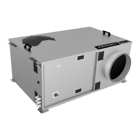
Other ViM Fan manuals

ViM
ViM JBRB ECOWATT PR User manual

ViM
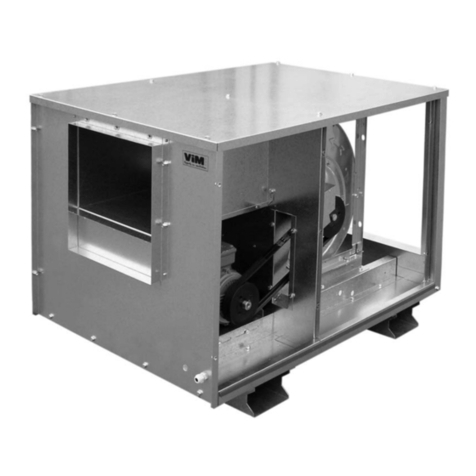
ViM KUBAIR F400 User manual

ViM
ViM TEDH F400 User manual

ViM
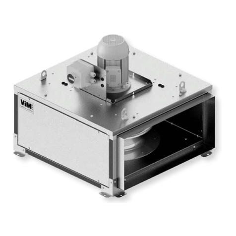
ViM KUBAIR F400 ECOWATT User manual

ViM
ViM TEDH F400 User manual

ViM
ViM KUBAIR F400 ECOWATT User manual

ViM
ViM JBRB ECOWATT PR VCHV User manual

ViM
ViM TEDH F400 User manual

ViM
ViM KUBAIR F400 ECOWATT CC User manual

ViM
ViM KDTA-R F400 User manual
Popular Fan manuals by other brands

Lindab
Lindab FORMO PKA installation instructions

Hunter
Hunter Vancouver 21328 Manual de Installatión y Operatión

Titon
Titon Titon Ultimate dMEV product manual

Lütze
Lütze AirBLOWER operating instructions

Lennox
Lennox FLATAIR KFC Series Installation and operating manual

Hyundai
Hyundai H-SF16-RC02 instruction manual