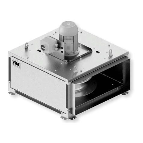
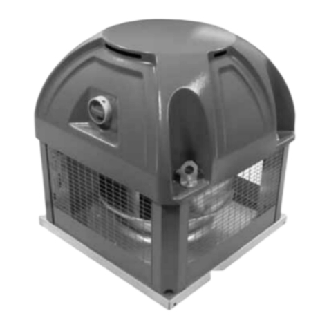
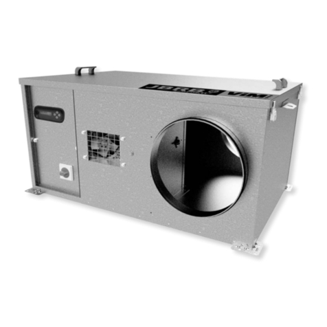
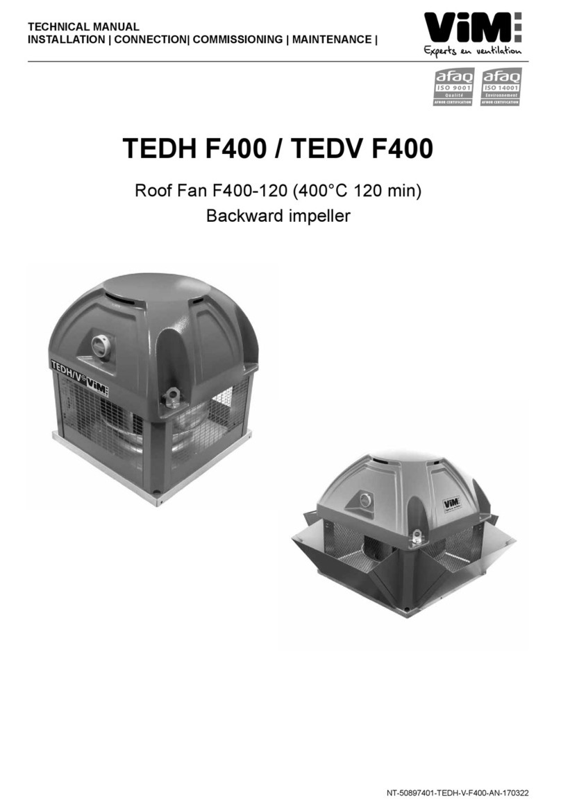
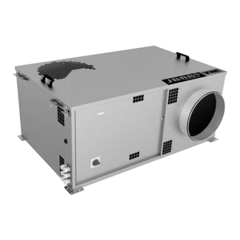
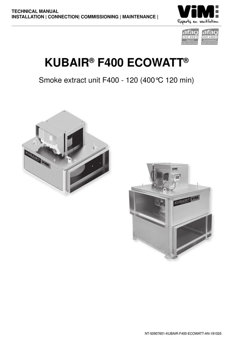
ViM KDTA-R F400 User manual

NT00000439-KDTA-F400-KDTR-F400-AN-210121
INSTRUCTION MANUAL
INSTALLATION | WIRING | COMMISSIONING | MAINTENANCE |
AFNOR CERTIFICATION
ISO 14001
Environnement
AFNOR CERTIFICATION
ISO 9001
Qualité
KDTA-R F400
F400 120mn extraction fan unit
Backward and forward curved impeller

2/16 NT00000439-KDTA-F400-KDTR-F400-AN-210121
INDEX
1. GENERAL POINTS............................................................................................................................ 3
1.1 Warnings .................................................................................................................................. 3
1.2 Safety instructions ................................................................................................................... 3
1.3 Acceptance - Storage............................................................................................................... 4
1.4 Warranty................................................................................................................................... 4
2. PRODUCT PRESENTATION.............................................................................................................. 4
3. INSTALLATION .................................................................................................................................. 5
3.1 Dimensions and weight ............................................................................................................ 5
3.2 Accessory assembly diagrams................................................................................................. 6
3.3 Accessories.............................................................................................................................. 7
3.4 Handling ................................................................................................................................. 10
3.5 Casing assembly.................................................................................................................... 10
4. ELECTRICAL CONNECTION...........................................................................................................11
4.1 Preliminary precautions...........................................................................................................11
4.2 Wiring without any safety switch ............................................................................................ 12
4.3 Wiring with a mounted and connected safety switch ............................................................. 13
4.4 Wiring with control panel (used in France)............................................................................. 13
4.5 Electrical connection of pressure switch................................................................................. 13
5. START-UP ........................................................................................................................................ 13
6. MAINTENANCE................................................................................................................................ 14
6.1 Upkeep................................................................................................................................... 14
6.2 Variable pulley adjustment...................................................................................................... 15
7. WASTE MANAGEMENT.................................................................................................................. 15
7.1 Treatment of packaging and non-hazardous waste ............................................................... 15
7.2 Professional WEEE treatment................................................................................................ 15

3/16 NT00000439-KDTA-F400-KDTR-F400-AN-210121
1. GENERAL POINTS
1.1 Warnings
This product has been manufactured according to rigorous technical rules of safety in conformity with EC
standards. The EC declaration may be downloaded from the Internet site (address given on the last page).
Before installing and using this product, carefully read these instructions, which contain important indica-
tions for your safety and the user’s safety during the installation, commissioning and maintenance of
this product. Once the installation is terminated, keep this manual handy nearby the machine for future
consultation.
This product must be installed (installation, connections, commissioning, maintenance) and all other inter-
ventions performed by a professional applying recognized good practice procedures, and respecting the
standards and safety regulations in force. The installation must be made in accordance with the prescrip-
tions indicated in the Electromagnetic Compatibility (EMC) and Low Voltage (LV) Directives.
We advise all people exposed to risks to scrupulously respect the accident prevention standards. The ma-
nufacturer may not be held liable for any human injury and/or material damage resulting from the non-res-
pect of the safety instructions or from a change made on the product.
The KDTAF400 and KDTR F400 smoke extracting units are designed for smoke extraction and ventilation
applications in residential buildings, commercial buildings, industrial and logistics buildings and covered
car paks :
• Interior or exterior installation
• Ambient temperature: -20°C / +50°C
• Relative humidity: max. of 95% without any condensation
• Non-potentially explosive atmosphere
• Atmosphere with low salinity, without any corrosive chemical agents.
1.2 Safety instructions
• Wear suitable PPE (Personal Protective Equipment) before any intervention.
• Before installing the extraction fan unit and its accessories, make sure that the support and the loca-
tion are suciently resistant to withstand the complete unit's weight.
• Do not open the access panels before the power is cut at the lockable safety switch present on the
unit.
• If any work is to be performed on the device, cut o the power supply at the main circuit-breaker and
make sure that no one is able to turn it back on accidentally.
• Make sure that moving parts are stopped.
• Make sure that the impeller is not accessible from connection tappings (connection duct or mesh
protection)
• If the suction or discharge holes of the unit are not connected, use an appropriate guard AVRZ,
PPHZ or APC.
Before starting, check the following points:
• Make sure that the device does not contain any foreign body.
• Make sure that all the components are attached to their original locations.
• Check manually that the impeller does not rub or is not blocked.
• Make sure that the ground connection is connected.
• Make sure the access panel is well locked.
4/16 NT00000439-KDTA-F400-KDTR-F400-AN-210121
1.3 Acceptance - Storage
In case of missing items or delivery of non conforming, partially or totally damaged products, the Buyer
shall make, in accordance with article 133-3 of the French Commercial Code, reservations in writing on the
transporter receipt and conrm them within seventy-two (72) hours by registered letter along with a copy
addressed to the seller. Should the Buyer fail to make reservations when he receives the equipment, he
will not be allowed to make any future claim against us.
The product must be stored protected from the weather, shocks and dirt due to splashings or splatterings
of any kind during transport from the supplier to the end customer, and onto the worksite before installation.
1.4 Warranty
The equipment is guaranteed for 24 months from the invoice date. The warranty is limited to the repla-
cement of parts or equipment whose operation is recognized as defective by maker, excluding any com-
pensation or penalties. The costs of labor, removal and rest, travel related to the replacement are the
responsibility of the Customer. Excluded from our warranty are defects linked to abnormal use or not in
accordance with the recommendations in our instructions, defects observed as a result of normal wear and
tear, incidents caused by negligence, lack of monitoring or maintenance, defects due to incorrect installa-
tion of devices or poor storage conditions prior to assembly.
In any case, maker is not responsible for transformed material, even partially repaired.
2. PRODUCT PRESENTATION
• F400 120 certied (400°C 120 mn) n°. 1812-CPD-0129 and n°. 1812-CPD-0130.
• KDTA: dynamically balanced galvanised steel double inlet forward curved impeller.
• KDTR: dynamically balanced galvanised and coated steel double inlet backward curved impeller.
• Mono bloc unit made from galvanised steel plates.
• Discharge in line (horizontal) or on the top (vertical).
• Two crosswise omegas which guarantee the stiness of the unit and allow slings to pass through for
lifting.
• Detachable lateral panels on 2 sides for ease of access.
• Transmission-motor unit mounted inside the unit.
• Motor out of air ow mounted on a tray with sliding rail to adjust the belt tightness.
• Available in kitchen version with backward curved fan, variable pulley and drain: KCTR model.

5/16 NT00000439-KDTA-F400-KDTR-F400-AN-210121
3. INSTALLATION
3.1 Dimensions and weight
Horizontal discharge
B
Asp. G
Asp. F
Q
M
Fix. D
C
AH
R Fix. E
Ref. J
Ref. H
N
102
Réf. H
Vertical discharge
M
Q
C
CV
Asp. G
Asp. F
B
Fix. D R Fix. E
P Ref. H
AV
102
Ref. H
Size AH AV B C CV D E F G H J M N P Q* R*
200
993 981 595 703 742 555 680 400 500 258 182 249 392 500 28 125
250
1130 1118 727 784 824 679 766 500 600 324 209 221 411 569 28 125
280
1177 1168 824 776 816 780 777 600 700 362 230 146 379 609,5 28 125
315
1360 1329 896 876 916 860 767 600 700 408 281 221 416 683,5 28 125
355
1490 1457 1006 990 1030 966 897 700 800 457 321 221 476 744 28 125
400
1594 1565 1120 1036 1078 1071 926 800 900 509 353 184 471 753 28 125
450
1761 1734 1191 1119 1162 1143 1130 900 1000 570 381 184 486 825 39 182
500
1919 1891 1387 1222 1264 1340 1180 900 1000 640 467 249 521 964 39 182
560
1919 1891 1387 1269 1310 1340 1180 1000 1100 718 505 189 492 999 39 182
630
2132 2104 1575 1464 1473 1507 1016 1200 1300 806 566 177 567 1070 44 240
710
2292 2264 1765 1614 1623 1697 1176 1200 1400 900 661 286 617 1125 44 240
* PAVZ: anti-vibration pads delivered accessories
Size Axis height Weight **
KDTA KDTR
standard insulated standard insulated
200
112 60 73 60 73
250
132 70 77 70 77
280
132 84 101 87 104
315
132 110 134 110 134
355
160 145 175 145 175
400
160 210 247 210 247
450
180 230 275 230 275
500
200 290 342 295 347
560
200 316 360 328 372
630
200 451 515 467 531
710
200 541 619 561 639
** Fan weight (kg) without motor, with transmission.

6/16 NT00000439-KDTA-F400-KDTR-F400-AN-210121
3.2 Accessory assembly diagrams
AVRZ
RCAZ
TPKD VSKZ
RRKZ
RCAZ
RCAZ
PPVZ TPKD
RCRZ RCAZ
PPHZ
VSKZ
RRKZ
TPKD
RCAZ
VSKZ
RRKZ

7/16 NT00000439-KDTA-F400-KDTR-F400-AN-210121
3.3 Accessories
H
L
A
A
A
60°
Water proof gasket
Model PPVZ
Water proof gasket Model PPVZ
Water proof gasket
A H L A H L
200 260 387 492 450 572 800 1083
250 326 473 615 500 642 893 1217
280 364 526 690 560 720 1000 1370
315 410 587 778 630 808 1113 1532
355 459 653 873 710 902 1240 1714
400 511 720 969
Rain hood
Model PPHZ
Rain hood Model PPHZ
Rain hood
S T S T
200 258 211 450 570 356
250 324 242 500 640 388
280 362 260 560 718 425
315 408 281 630 806 466
355 457 304 710 900 510
400 509 328
AxA
E
Exhaust side bird proof guard
Model AVRZ
Exhaust side bird proof
guard Model AVRZ
Exhaust side bird proof
guard
A E A E
200 260 50 450 572 50
250 326 50 500 642 50
280 364 50 560 720 50
315 410 50 630 808 50
355 459 50 710 902 50
400 511 50
V
A
A
Over-pressure aps
Ensures good water and air tightness when the unit is stopped. Sup-
plied with 4 bolts for xing to the unit.
Take into account 50 Pa air pressure drop.
Model VSKZ
Over-pressure aps Model VSKZ
Over-pressure aps
A V A V
200 260 335 450 572 304
250 326 401 500 642 330
280 364 439 560 720 300
315 410 311 630 808 322
355 459 335 710 902 345
400 511 284
PPVZ
PPHZ
AVRZ
VSKZ

8/16 NT00000439-KDTA-F400-KDTR-F400-AN-210121
G
F
ØD
30
L
Inlet circular connection
This connection is used for a duct connection, which does not support
the weight of the plenum.
Model RCAZ
Circular connection
Inlet Model RCAZ
Circular connection
Outlet
ØD F G L ØD F G L
200 355 402 502 80 450 710 902 1002 100
250 400 502 602 80 500 800 902 1002 100
280 500 602 702 80 560 900 1102 1202 100
315 500 602 702 80 630 1000 1202 1302 100
355 560 702 802 80 710 1250 1202 1402 80
400 630 802 902 65
D
50
30
A int.
A
in
t.
ØD ext.
Outlet circular connection
This connection is used for a duct connection, which does not support
the weight of the plenum.
Model RCRZ
Circular connection
Outlet Model RCRZ
Circular connection
Outlet
A D A D
200 260 355 450 572 710
250 326 400 500 642 800
280 364 500 560 720 900
315 410 500 630 808 1000
355 459 560 710 902 1250
400 511 630
B
C
A
External roof
Model TPKD
External roof Model TPKD
External roof
A B C A B C
200 1048 699 775 450 1784 1297 1215
250 1185 834 861 500 1944 1494 1326
280 1234 928 858 560 1944 1494 1373
315 1385 1000 959 630 2148 1679 1540
355 1514 1110 1078 710 2308 1869 1734
400 1616 1229 1128
R
A
A
F
O
Manual airow adjusting damper
Attaches to the discharge using the 4 bolts supplied.Allows to reduce
and adjust the airow.
The ap swivels from 0 to 90° and locks with a knurled handle.
Model RRKZ
Manual airow adjusting
damper Model RRKZ
Manual airow adjusting
damper
A R A R
200 260 240 450 572 428
250 326 280 500 642 470
280 364 303 560 720 516
315 410 330 630 808 569
355 459 360 710 902 626
400 511 391
RCAZ
RCRZ
TPKD
RRKZ

9/16 NT00000439-KDTA-F400-KDTR-F400-AN-210121
RRKZ Air performances
F
O
The airow adjustment of a RRKZ depends on the initial pres-
sure airow running point and the type of fan.
This damper allows a higher airow adjustment with a KDTA
forward curved fan, whose airow varies more with pressure
than a KDTR backward curved fan.
KDTA F400 + RRKZ
P
stat
(Pa)
Qv (m3/h)
-30%
-25%
Qv 1
-5% Qv 4
Qv 3
Qv 2
-15%
Plage d’utilisation volet RRKZ
RRKZ airow adjustment range
KDTR F400 + RRKZ
P
stat
(Pa)
-15%
-12%
Qv 1
Qv 4
Qv 3
Qv 2
-10%
Qv (m3/h)
-5%
Plage d’utilisation volet RRKZ
RRKZ airow adjustment range
For a KDTA running point located at the beginning of the curve it will be able to reduce its airow by a
maximum of 5% while at the end of the curve it will be able to reduce it by up to 30%.

10/16 NT00000439-KDTA-F400-KDTR-F400-AN-210121
3.4 Handling
KDTA -R Horizontal Nu
CaissonActionTransmission
Puissance
Intensité
Vitessederotation
Product identication label
Ventilation slit
Do not obstruct
Pass the slings through
the guides
Characteristics of the unit: See product identication label on the side of the unit
3.5 Casing assembly
3.5.1 Horizontal installation
Anti-vibration pads
(xed to oor only)
The use of anti-vibration pads is advised.
• Installation with exible sleeves on the air ow network is strongly
advised in order to prevent the transmission of vibrations.
• Leave a minimum distance (L) of 60cm on the transmission side
for any technical work to be performed.
• Do not obstruct the ventilation slits on either side of the unit.
3.5.2 Vertical installation
KDTA-RHorizontalNu
CaissonActionTra nsmission
Puissance
Intensité
Vit es sederotation
Use wide
washers (LL)
Flexible
sleeves
Only sizes 200 to 355
• Never install anti-vibration pads for a vertical attachment.
• Installation with exible sleeves on the air ow network is strongly
advised in order to prevent the transmission of vibrations.
• Leave a minimum distance of 60cm on the transmission side for
any technical work to be performed.
• Do not obstruct the ventilation slits on either side of the unit.

11/16 NT00000439-KDTA-F400-KDTR-F400-AN-210121
Vertical attachment to a wall for KDTA-R 200 to 355:
Size Min. resistance of each xture
(Kg) Ø of attachment holes
(mm)
200
118.5 11
250
149 11
280
172 11
315
206 13
355
296 13
• For control panels with sizes 2 up to 4, to prevent the panel from
getting unhooked when the unit is placed in a vertical position,
loosen the screw located on the side of the control panel bracket
and tighten it in the indicated place.
4. ELECTRICAL CONNECTION
4.1 Preliminary precautions
Electrical connections must be made by qualied personnel. Do not forget the earthing connection.
In addition, the cables routing must be protected from mechanical aggressions when the connection is
made to the motor's terminal box or to the unit's safety switch. The cable must be protected from UV ra-
diation.
If used for comfort application, the electric motor must be protected by a suitable magnetothermal protec-
tion device.
The direction of rotation of the wheel must correspond for each speed to the direction indicated
by the arrow located on the product. Any unit whose wheel does not turn in the right direction will
create a ow and negative pressure in the duct. An incorrect direction of rotation causes the motor
to overheat which may render it unsuitable for use; this invalidates our manufacturer's warranty.

12/16 NT00000439-KDTA-F400-KDTR-F400-AN-210121
4.2 Wiring without any safety switch
Disassemble the lateral panel of the unit using a 13 mm wrench. Connect the supply lead directly to the
motor's terminal block (cable glands are provided).
Single-phase motors
V2U2
W2
U1 V1 W1
PE
NPh
0GV
Moteur 1V
Alim mono
230 VAC 50Hz
Moteur 1V
Alim mono
230 VAC 50Hz
V2U2
W2
U1 V1 W1
PE
NPh
0GV
1 Speed motor
single-phase alimentation
230 VAC 50 Hz
1 Speed motor
single-phase alimentation
230 VAC 50 Hz
HS HS
Perform a start-up test lasting a few seconds in order to check the direction of rotation of the fan. If the
direction of rotation is incorrect, invert 2 phases (three-phase motors).
Nb. in the case of two-speed motors, check the direction of rotation of the fan for the two speeds.
Three-phase motors
U1V1
W1
V2 U2 W2
Moteur D230/Y400V
Moteur 1V
Alim tri
230 Vac 50Hz
PE
L2 L3L1
0GV
U1V1
W1
V2 U2 W2
Moteur D230/Y400V
Moteur 1V
Alim tri
400 Vac 50Hz
PE
L2 L3L1
0GV
HS HS
1 Speed motor
three-phase alimentation
400 VAC 50 Hz
1 Speed motor
three-phase alimentation
230 VAC 50 Hz
D230/Y400V Motor D230/Y400V Motor
Motors with independent or Dahlander windings
U1
V1
W1 PE
0GV
L1
Moteur 2V Bobinages Indépendants Y/Y
Alim tri
400 Vac 50Hz
GVPV
PV
V2 U2 W2
L2 L3
U1
V1
W1 PE
0GV
L1
Moteur 2V Bobinages Dahlander Y/YY
Alim tri
400 Vac 50Hz
GV GV
PV
PV
V2 U2 W2
L2 L3
2 Speed motor independent windingsY/Y
three-phase alimentation
400 VAC 50 Hz
2 Speed motor Dahlander windings Y/YY
three-phase alimentation
400 VAC 50 Hz
HS
HS LS
LS LS
LS HS
HS HS
Close the motor's terminal block and re-assemble the lateral panel of the unit.

13/16 NT00000439-KDTA-F400-KDTR-F400-AN-210121
4.3 Wiring with a mounted and connected safety switch
Disassemble the lateral panel of the unit using a 13 mm wrench. Connect the supply lead to the safety
switch (cable glands are provided) according to the label axed to the unit. Perform a start-up test lasting
a few seconds in order to check the direction of rotation of the fan. If the direction of rotation is incorrect,
invert 2 phases (three-phase motors). Nb. in the case of two-speed motors, check the direction of rotation
of the fan for the two speeds. Close the safety switch's enclosure and re-assemble the lateral panel of the
unit.
4.4 Wiring with control panel (used in France)
Connect the supply lead to the control panel according to the instructions that come with this device (cable
glands are provided). Perform a start-up test lasting a few seconds in order to check the direction of rota-
tion of the fan. If incorrect, invert 2 phases on the supply terminal block of the control panel (three-phase
motor).
If a comfort-smoke extract control panel is used, see the instructions that come with this device.
4.5 Electrical connection of pressure switch
If the pressure switch is factory assembled, it is tted to the inside of the unit on the motor side. Open the
lateral panel of the unit and then the hood located on the pressure switch. Connect the 2 connection cable
threads.Adjust the triggering value of the pressure switch. Close the hood of the pressure switch and then
the lateral panel of the unit.
5. START-UP
In order to start up the fan, make sure that the whole unit, including fan, motor and transmission, rotates
freely and that there is no object that may be projected by the fan. The unit must be connected to the air
ow network and the lateral panels must be closed. The machine must be attached to its stand before
being power is applied.
Switch on just an instant to check the direction of rotation of the turbine.
WARNING: The impeller rotating direction must correspond to each speed in the direction indi-
cated by the arrow on the product. A centrifugal backward fan unit with an impeller that does not
rotate in the right direction still creates a lowrate and a low pressure in the duct. An incorrect ro-
tating direction can lead to an abnormal overheating of the motor, resulting in its destruction and
cancelling our manufacturer’s warranty.
If the rotating direction is incorrect, cut o the electrical power supply, make sure no power is pre-
sent, and then reverse the two power supply phases at the level of the motor’s terminal box for the
three-phase motors, or make sure that the mains network connection conforms to the schematic
diagram of § "4. ELECTRICAL CONNECTION", page 11 for the single-phase motors.
While running, make sure that the motor’s absorbed current is not more than 5% above the name plate
indicated current.
Once the installation and tests have ended, present the main points of the operating and maintenance
manual to the user; the following should be explained:
• How to start up and shut down the device.
• How to change the operating modes.
Then hand over to the user with the technical instructions for use of the casing and assembled accessories
(control panel, etc.) so that they can be accessed at all times.

14/16 NT00000439-KDTA-F400-KDTR-F400-AN-210121
6. MAINTENANCE
6.1 Upkeep
The frequency of the maintenance depends on operating conditions and must comply with regulationsIf
the air is heavily contaminated with dust, the duration between two visits must be shortened. Generally,
the fan must be inspected at least twice a year.
FREQUENCY OF MAINTENANCE
Component At commissioning Each 6 month minimum
Fan Check the rotating direction; make sure
that the moving and xed parts do not
rub together
Clean, if necessary ; make sure that
the moving and xed parts do not rub
together
Motor Check the connections, in particular the
ground connection Retighten the lugs, if necessary ; check
the nominal current
Safety switch Check the connections, in particular the
ground connection Retighten the lugs, if necessary
Pressure switch Check the electrical/aeraulic
connections Check the operation
Control box Make sure that there are no defects ;
check the connections, in particular, the
ground connection Make sure that there are no defects ;
retighten the lugs, if necessary
Protection guards Make sure that they are present Clean, if necessary
Duct network Make sure that there are no leaks Clean, if necessary
Fixing Check the mechanical tightness Retighten the screws, if necessary
When you use new belts, their tension must be checked and adjusted after 30 minutes of operation, if
necessary.
Check the wear and tension of the belt followed by the belt tension as follows:
• Apply a force F as indicated in the diagram below in order to obtain an arrow f (mm) = 16xA (m).
• The force F that is applied is variable according to the diameter of the smallest pulley and the type
of belt.
A
Ød
F
f
Type of belt D
(mm) F
(Kg)
SPZ 67-95 1.0-1.5
100-140 1.5-2.0
SPA 90-132 1.8-2.7
140-200 2.8-3.5

15/16 NT00000439-KDTA-F400-KDTR-F400-AN-210121
6.2 Variable pulley adjustment
Variable pulley adjustment (optional)
Cut o the power supply before any work is performed and make sure that it cannot be re-established
accidentally.
• Loosen the four clamping screws on the side of the motor bracket.
• Untighten the belt by loosening the adjusting screw provided.
• According to the kind of variable pulley:
Loosen the 4 clamping screws, with hexagonal
socket head, adjust the mobile ange and tighten
the 4 screws again.
Loosen the 2 clamping screws, with hexagonal
socket head, adjust the mobile ange and tighten
the 2 screws again, while making sure that they
press against the bottom of the 2 grooves, so that
the threading of the pulley is not damaged.
To reduce the rotation speed: loosen the mobile ange To increase the rotation speed: tighten the mobile
ange.
WARNING: The rotation speed of the fan must never exceed the maximum rotation speed indicated
on the product identication label.
7. WASTE MANAGEMENT
7.1 Treatment of packaging and non-hazardous waste
Any packaging (no-return pallets, cardboard, lm, wooden packaging) and other non-hazardous waste
must be recovered by an approved service provider.
It is strictly forbidden to burn, bury or leave it in a wild deposit.
7.2 Professional WEEE treatment
This product must not be dumped or treated with household refuse, but must be deposited in an appro-
priate collection point for waste electrical and electronic equipment (WEEE).

16/16 NT00000439-KDTA-F400-KDTR-F400-AN-210121
Non-contractual document. In a constant bid to improve equipment, the manufacturer reserves the right
to undertake any technical alteration without any notice.
VIM
Les prés de Mégy Sud – SOUDAN
CS 60120 - 79401 ST MAIXENT L’ECOLE CEDEX
Tel.: 05 49 06 60 38 ot 05 49 06 60 25 – Fax: 05 49 06 60 36
Table of contents
Other ViM Fan manuals

ViM
ViM JBRB ECOWATT PR VCHV User manual

ViM
ViM TEDH F400 User manual

ViM
ViM TEDH F400 User manual

ViM
ViM KUBAIR F400 ECOWATT User manual

ViM
ViM KUBAIR F400 User manual

ViM
ViM KUBAIR F400 ECOWATT User manual

ViM
ViM TEDH F400 User manual

ViM
ViM JBRB ECOWATT PR User manual

ViM
ViM TEDH F400 User manual

ViM
ViM KUBAIR F400 ECOWATT CC User manual
Popular Fan manuals by other brands

Lindab
Lindab FORMO PKA installation instructions

Hunter
Hunter Vancouver 21328 Manual de Installatión y Operatión

Titon
Titon Titon Ultimate dMEV product manual

Lütze
Lütze AirBLOWER operating instructions

Lennox
Lennox FLATAIR KFC Series Installation and operating manual

Hyundai
Hyundai H-SF16-RC02 instruction manual