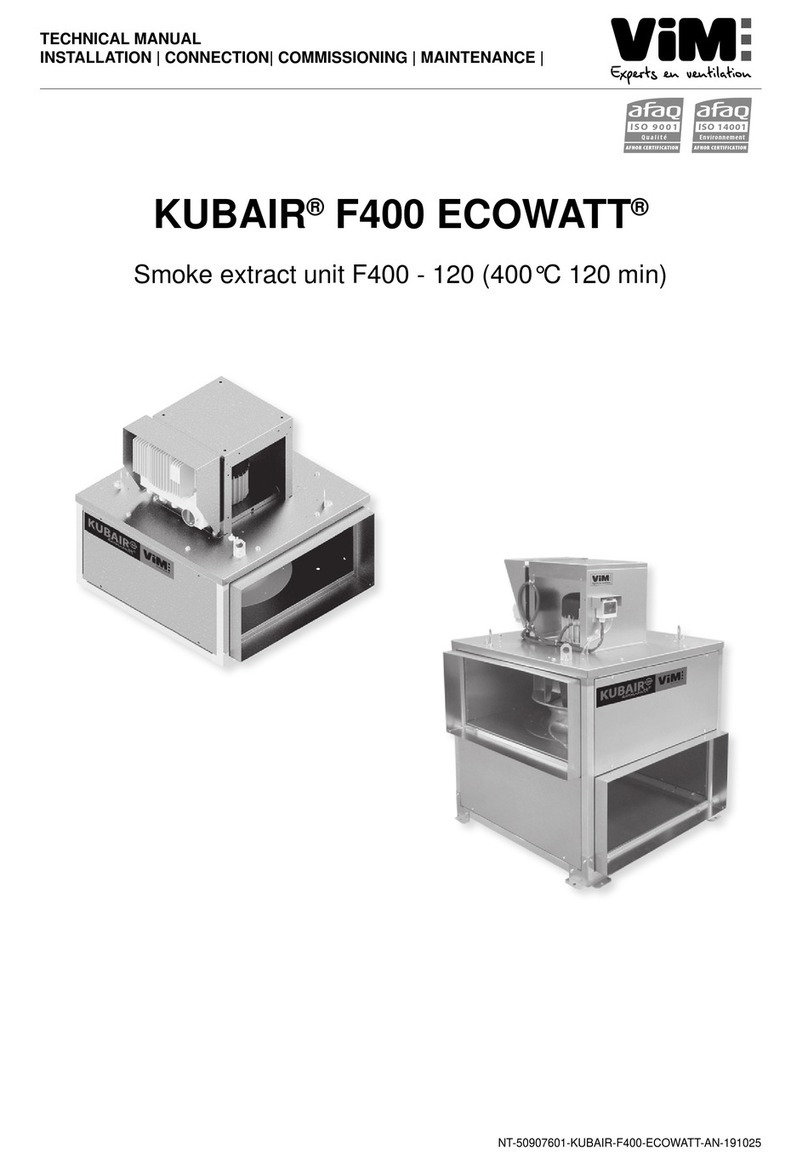
ViM TEDH F400 User manual

NT_50897401_TEDH-V F400-AN_140115.docx
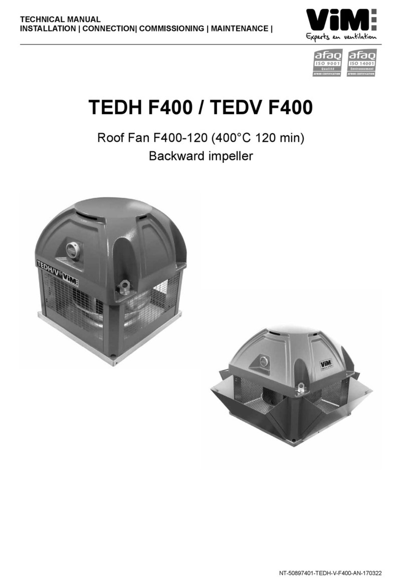
TECHNICAL MANUAL
INSTALLATION |CONNECTION| COMMISSIONING | MAINTENANCE |
TEDH F400 / TEDV F400
Roof Fan F400-120 (400°C 120 min)
Backward impeller

2/24 NT_50897401_TEDH-V F400-AN_140115.docx
CONTENTS
1.GENERAL...................................................................................................................................................... 3
1.1Disclaimers ................................................................................................................................................. 3
1.2Safety instructions ..................................................................................................................................... 3
1.3Acceptance – Storage ............................................................................................................................... 3
1.4Warranty ...................................................................................................................................................... 4
2.PRODUCT PRESENTATION ....................................................................................................................... 4
3.INSTALLATION ............................................................................................................................................ 5
3.1Dimensions and weight ............................................................................................................................. 5
3.2Handling ...................................................................................................................................................... 6
3.3Mounting roof fan accessories ................................................................................................................ 7
3.4Removing the caps .................................................................................................................................. 11
3.5Mounting the roof fan .............................................................................................................................. 11
3.6Mounting the roof fan deflectors ........................................................................................................... 11
4.ELECTRICAL CONNECTION .................................................................................................................... 13
4.1Preliminary precautions .......................................................................................................................... 13
4.2Technical data ........................................................................................................................................... 14
4.3Wiring of version without INTZ safety isolation switch ...................................................................... 16
4.4Wiring of version with INTZ safety isolation switch ............................................................................ 17
4.5Wiring of the PILOTAIR® control panel (used in France) .................................................................... 18
4.6Wiring of the frequency inverter ............................................................................................................ 18
4.7Electrical connection of the pressure switch ....................................................................................... 19
5.COMMISSIONING ....................................................................................................................................... 19
6.MAINTENANCE .......................................................................................................................................... 20
6.1Maintenance periodicity .......................................................................................................................... 20
6.2Removing the mesh grille to access the impeller ............................................................................... 20
7.WASTE MANAGEMENT ............................................................................................................................ 21
7.1Treatment of Packagings and non dangerous wastes ....................................................................... 21
7.2Treatment of a Professional WEEE ....................................................................................................... 21
8.APPENDICES.............................................................................................................................................. 22

3/24 NT_50897401_TEDH-V F400-AN_140115.docx
1. GENERAL
1.1 Disclaimers
This product has been manufactured according to rigorous technical rules of safety in conformity with EC
standards. The EC declaration may be downloaded from the Internet site (address given on the last page).
Before installing and using this product, carefully read these instructions, which contain important indications
for your safety and the user’s safety during the installation, commissioning and maintenance of this product.
Once the installation is terminated, keep this manual handy nearby the machine for future consultation.
This product must be installed (installation, connections, commissioning, maintenance) and all other
interventions performed by a professional applying recognized good practice procedures, and respecting the
standards and safety regulations in force. The installation must be made in accordance with the prescriptions
indicated in the Electromagnetic Compatibility (EMC) and Low Voltage (LV) Directives.
We advise all people exposed to risks to scrupulously respect the accident prevention standards. The
manufacturer may not be held liable for any human injury and/or material damage resulting from the non-
respect of the safety instructions or from a change made on the product.
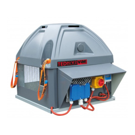
The TEDH F400 and TEDV F400 centrifugal backward roof fans are intended for smoke extraction and
ventilation applications in residential buildings, tertiary buildings, industrial buildings and professional kitchens:
Outdoor installation
Environmental temperature range: -20°C / +50°C
Max temperature of extracted air in permanent operation: 120°C
Relative humidity: max 95% non-condensing
Atmosphere not potentially explosive
Low salinity atmosphere, with no corrosive chemical agents
1.2 Safety instructions
Wear suitable PPE (Personal Protective Equipment) before any intervention.
Before installing the roof fan and its accessories, make sure that the support and the location are
sufficiently resistant to withstand the unit’s weight and the accessories, if any.
Do not remove mesh grilles to access the impeller before cutting off the electric power supply with the
disconnector switch present on the unit safety.
If the work is to be done inside the device, cut off the electric power supply with the main circuit
breaker and make sure that nobody can accidentally switch it back on.
Make sure that moving parts are stopped.
Make sure that the impeller is not accessible from connection tappings (connection duct or mesh
protection).
Before starting, check the following points:
Make sure that the device does not contain any foreign body.
Make sure that all the components are attached to their original locations.
Check manually that the impeller does not rub or is not blocked.
Make sure that the mesh protection are in place.
Make sure that the ground connection is connected.
1.3 Acceptance – Storage
In case of missing items or delivery of non conforming, partially or totally damaged products, the Buyer shall
make, in accordance with article 133-3 of the French Commercial Code, reservations in writing on the
transporter receipt and confirm them within seventy-two (72) hours by registered letter along with a copy
addressed to the seller. Should the Buyer fail to make reservations when he receives the equipment, he will
not be allowed to make any future claim against us.
The product must be stored protected from the weather, shocks and dirt due to splashings or splatterings of
any kind during transport from the supplier to the end customer, and onto the worksite before installation.
4/24 NT_50897401_TEDH-V F400-AN_140115.docx
1.4 Warranty
The equipment is warranted for twelve (12) months – Parts only – from date of manufacture.
VIM agrees to replace parts or the equipment whose operation is recognised defective by our departments,
excluding all damages or penalties, such as operating losses, commercial prejudice, or other intangible or
indirect losses.
Our warranty does not cover: (1) defects resulting from an abnormal use or an use not conforming to the
recommendations indicated in our manuals; (2) defects observed following normal wear; (3) incidents caused
by negligence, lack of monitoring or maintenance; (4) defects due to the inappropriate installation of the
devices or unsuitable pre-installation storage conditions.
In any case, VIM may not be held liable for transformed or repaired equipment even partially.
2. PRODUCT PRESENTATION
EC Certificate F400-120 No. 1812-CPR-1085, according to European Standard NF EN 12101-3
Approved F400 120 (400°C 120min)
TEDH F400 : horizontal discharge.
TEDV F400 : vertical discharge.
15 sizes : 250/315/355/400/450/500/560/630/695/710/760/800B/800H/810/900.
Flowrates from 200 to 34 000 m3/h according to model
Construction :
High-performance impeller with backward inclined blades made of galvanised steel
Convergent/divergent inlet cones
Plate, arm and electric motor support made of galvanised steel.
2 to 4 lift legs according to size.
Mesh protection made of galvanised steel sheet metal, pre-lacquered grey RAL 7024. Meshes
conform to NF EN ISO 12499.
Arm caps and mesh protection made of sheet metal, pre-lacquered grey RAL 7024.
Cover cap made of ABS PMMA, pre-lacquered grey RAL 7024.
Vertical discharge version : addition of 4 deflectors made of sheet metal, pre-lacquered grey RAL
7024, delivered factory mounted (TEDV F400 model) or available as a kit for mounting on the worksite
(KRVT).
Standard electric motor with B5 flange, class F, three-phase version:
- 1 speed: 2, 4, 6 or 8 poles, 230/400V, 50Hz, IP55, IE1, IE2 or IE3, according to power rating
(accepts speed variation by frequency variation).
- 2 speeds: 4/6, 4/8, 6/8 and 6/12 poles, 400V, 50Hz, IP55.
Standard electric motor with B14 flange, class F, single-phase version (accepts speed variation by
voltage variation):
- 1 speed, 2, 4 or 6 poles, 230V, 50Hz, IP55.
60Hz power supply: F400 120 approved, with the VFTM option factory-mounted and wired: variator
60Hz power supply from the power network and variator output for the 50Hz power supply of the
centrifugal backward fan unit’s electric motor.

5/24 NT_50897401_TEDH-V F400-AN_140115.docx
3. INSTALLATION
3.1 Dimensions and weight
B
CV
F
AØ20
ØD
Fixing
Fixing E
B
CV
F
AØ20
ØD
Fixing
Fixing E
B
CV
F
AP Ø20
ØD
Fixing
Fixing E
B
CV
F
AØ20
ØD
Fixing
Fixing E
ModelA*B*HC*VC*D*E*F*P*
H
weight
(kg)
V
weight
(kg)
250 430 446 436 635 214,0 344 30 105 23 24
315 430 483 436 680 256,6 344 30 125 27 29
355 540 570 553 832 289,1 450 30 146 34 37
400 540 609 553 878 325,8 450 30 169 39 43
450 660 684 669 1038 366,5 570 30 190 54 65
500 660 698 669 1055 407,3 570 30 198 69 74
560 800 762 817 1219 455,2 668 30 209 87 95
630 800 805 817 1268 513,1 668 30 234 99 108
695 946 918 957 1291 541,0 830 30 173 128 142
710 946 1096 957 1492 577,9 830 40 273 172 188
760 946 940 957 1319 596,0 830 30 187 152 162
800B 946 1114 957 1512 650,9 830 40 284 264 275
800H 946 1172 957 1580 650,9 830 40 317 273 286
810 946 983 957 1352 646,0 830 40 204 212 220
900 1250 1253 1262 1874,8 732,3 1100 62 315 356 374
* Dimensions in mm

6/24 NT_50897401_TEDH-V F400-AN_140115.docx
3.2 Handling
To avoid injurying people or damaging the equipment, use
handling devices in conformity and in good condition.
For the sizes 250 and 315, the roof fan must be lifted with 2 lifting
lugs.
For other sizes, the roof fan must be lifted with 4 lifting lugs.
Use slings with lengths greater than or equal to twice roof fan
height. The caps must be removed before slinging (see §
Removing the caps). Make sure that the slings do not rub
against the dome. If in doubt, remove the dome to avoid damaging
it.
Standardised 400mm long slings are supplied with the products to
easily handle the roof fan units.
WARNING: Do not leave the slings on the product once it is
installed.
VIM shall be relieved of any responsibility in case these slings are
not properly used.
WARNING: Do not lift the product by holding it by the plastic
cover cap.

7/24 NT_50897401_TEDH-V F400-AN_140115.docx
3.3 Mounting roof fan accessories
* Some adaptation plate diameters are not compatible with the following accessories: TCDZ 02, 04, 07 and 08
(see § Adaptation plate).
3.3.1 Standard support: TCDZ 01
This assembly does not allow using an energy save flap or an adaptation plate. Make sure that the
duct can withstand the roof fan weight.
Install the 4 angle irons B and the 2 collars C on
the duct.
Install the seal A on the duct’s free edge.
Put the roof fan on the duct by centring it
correctly.
Adjust and fix the angle irons B on the assembly.
Tighten the 2 collars C.
B
C
A
SILS TCDZ06
TCDZ05*
TCDZ03
TCDZ08
TCDZ01 TCDZ04 TCDZ07 TCDZ02 TCDZ09
TCDZ03
TEDH TEDV
TEDH with
PILOTAIR
TEDV with
PILOTAIR
or
or or or
or
or or or
or
CBF Unit Min duct dia.
(mm)
Max duct dia.
(mm)
Weight
(kg)
250 200 315 3
315 250 315 3
355 315 355 3
400 355 355 3

8/24 NT_50897401_TEDH-V F400-AN_140115.docx
E
G
S
G
E
ØD
T
3.3.2 Embedding frame: TCDZ 02
Seal the frame in the concrete support and make sure
that the sealing pads are embedded in the concrete.
3.3.3 Energy saver flap : TCDZ 03
Mount the energy saver flap inside the inserts under the roof fan. This is incompatible with the use
of adaptation plates TCDZ 05 and the standard support TCDZ 01. Before mounting the roof fan,
make sure the flaps swing freely. Take into account 50Pa pressure drop.
3.3.4 Adaptation plate: TCDZ 05
The adaptation plate allows connecting roof fan to a circular
duct. Since it is designed to make the air connection, it is
not supposed to withstand roof fan weight. This is
incompatible with the use of the energy saver flap TCDZ 03
and the roof adapter with sound attenuator TCDZ 09.
* These adaptation plates cannot be mounted in the following accessories: TCDZ02, 04, 07 and 08.
E
G
M
K
A mini
Tower
si z e
Accessory
si z e A* E* G* S* Weight
(kg)
250/315 1 70 344 368 30 2
355/400 2 70 450 478 30 2,5
450/500 3 70 570 598 40 4
560/630 4 70 668 698 40 4,5
695-810 5 70 830 866 40 6
900 7 100 1100 1150 65 12
* Dimensions in mm
CBF unit size
A
cce ssory
si z e E* G* M* K* Weight
(kg)
250/315 1 344 368 145 300 3,5
355/400 2 450 478 145 400 5
450/500 3 570 598 170 490 6
560/630 4 668 698 170 605 8
695/810 5 830 866 190 730 11
900 7 1100 1150 190 970 24
* Dimensions in mm
GETØD G E TØD
250/315 Size 1 368 344 50 250 1 450/500 Size 3 598 570 80 560** 1,7
250/315 Size 1 368 344 50 315** 0,7 560/630 Size 4 698 668 80 450 5,1
250/315 Size 1 368 344 65 355** 0,4 560/630 Size 4 698 668 80 500 4,5
355/400 Size 2 478 450 50 315 1,8 560/630 Size 4 698 668 80 560 3,7
355/400 Size 2 478 450 65 355 1,5 560/630 Size 4 698 668 90 630 2,7
355/400 Size 2 478 450 80 400 1,2 695/810 Size 5 866 830 80 560 11,8
355/400 Size 2 478 450 80 450** 0,8 695/810 Size 5 866 830 90 630 10,3
450/500 Size 3 598 570 80 400 3,6 695/810 Size 5 866 830 120 710 8,3
450/500 Size 3 598 570 80 450 3,1 900 Size 7 1150 1100 120 710 21,8
450/500 Size 3 598 570 80 500 2,5
* Dimensions in mm
Dimensions * Weight
(kg)
Dimensions *
Model Acce sso ry
si z e
Weight
(kg) Model Acc e ssory
si z e

9/24 NT_50897401_TEDH-V F400-AN_140115.docx
3.3.5 Tipping-up kit: TCDZ 06
This kit allows safely swinging the roof fan for cleaning operations. It is placed on the embedding
frames TCDZ 02, roof adapters TCDZ 04, TCDZ 07 or TCDZ 09 and can be placed on top of the
adaptation plates TCDZ 05 or the energy saver flap TCDZ 03.
Notes:
Make sure that there is a sufficient height between the floor and the roof fan plate so that
the roof fan does not touch the floor/ground when it swings.
Make sure that the power cables
lengths are sufficiently long to allow
swinging the machine without
stressing them.
Make sure that the support is correctly
attached to the floor and can withstand the
shearing stress due to the swinging of the
roof fan.
Position the hinge and fasten it with
the 2 flat nuts supplied
Tie up a chain extremity to the lug
piece with the HM18x16 bolt provided
Position the undrilled side of the
safety bar in the lug piece and fit the
assembly on the support
Fasten the lug piece with the 2 flat
nuts supplied
Glue the foam seal on the support
Position the roof fan on the kit (pay particular
attention to the plate’s direction)
Screw the 2 HM8x20 screws in the hinge’s
crimped nuts
Tie up the free chain extremity to the roof fan
plate with an HM8x16 bolt supplied
Lift the roof fan and immediately install the
safety bar and lock it with the safety pin
Glue the instruction label near the safety bar
The roof fan must be attached to its support when
commissioned.
hinge
lug piece
Safety
bar
chain
Foam
seal

10/24 NT_50897401_TEDH-V F400-AN_140115.docx
CBF unit
si z e
Acce ssor y
si z e E* G* N* R* Weight (kg)
TCDZ 04
Weight (kg)
TCDZ 07 30°
angle
Weight (kg)
TCDZ 09
250/315 1 344 368 568 300/500/700 8,5/12/15,5 8,2 23,5
355/400 2 450 478 678 300/500/700 11/15,5/20 11,2 34
450/500 3 570 598 798 300/500/700 13,5/19/25 14,8 51
560/630 4 668 698 898 300/500/700 20,5/29,5/38 24,2 65,5
695/810 5 830 866 1066 300/500/700 25,5/37/48 32,4 90,5
900 7 1100 1150 1350 300/500/700 53/76/98 77,2 164
* Dimensions in mm
3.3.6 Sound attenuators : SILS
Provide for an 80 Pa pressure drop.
3.3.7 Horizontal and inclined roof adapters: TCDZ 04, TCDZ 07 or TCDZ 09
It is possible to associate an energy save flap TCDZ 03 or an adaptation plate TCDZ 05 (except for
TCDZ 09) placed inside the insert.
For roof fan with acoustic straight insert (TCDZ 09), take into account a 80Pa pressure drop
3.3.8 Roof adapter heightener: TCDZ 08
Allows to rise the roof fan by 200mm, allows to insert an
adaptation plate TCDZ 05 between roof fan and the energy
saver flap TCDZ 03, or to mount an energy saver flap TCDZ
03 on an embedding frame TCDZ 02.
A
E
E
Ø19
Ø12
J
CBF unit
si z e
Acce ssory
si z e E* G* Weight
(kg)
250/315 1 344 368 4,8
355/400 2 450 478 6,2
450/500 3 570 598 10,5
560/630 4 668 698 12,2
695/810 5 830 866 15
900 7 1100 1150 31,4
* Dimensions in mm
CBF
unit
si z e
Accessory
si z e A* J* E* G* Weight
(kg)
250/315 1 430 630 344 368 15
355/400 2 540 630 450 478 23
450/500 3 660 700 570 598 37
560/630 4 800 700 668 698 45
695/810 5 930 700 830 866 65
900 7 1250 800 1100 1150 111
* Dimensions in mm
200
E
TCDZ08
TCDZ04
TCDZ05
TCDZ03
E
G
N
R
100
TCDZ 04
E
G
150
100
100
TCDZ 07
E
G
N
800
100
TCDZ 09

11/24 NT_50897401_TEDH-V F400-AN_140115.docx
Self drilling screw
Ø4.2
Vertical
deflector
3.4 Removing the caps
To remove the caps :
Raise the cap slightly upward.
Pull the cap outward.
The plastic top cap does not have to be removed.
3.5 Mounting the roof fan
The support surface, which will support the roof fan base, must also be as flat as possible (embedding frame
or roof adapter supplied on request). A foam seal, or equivalent (not supplied), is recommended between the
support surface and the roof fan base. A maximum tilting of 2.5° between the motor axis and the vertical is
tolerated (see figure below).
The roof fan base must completely cover the support to ensure a good tightness.
Make sure that the support is adapted to withstand the combined weight of the machine and its various
accessories. Fasten roof fanusing the 20mm dia. holes provided for this purpose. It is recommended to use
the LL washers. If the fastening screws are not correctly tightened, it can lead to disturbing noises and
vibrations. Once the machine is correctly attached, make sure that the impeller rotates freely without rubbing
or noise.
3.6 Mounting the roof fan deflectors
3.6.1 Vertical discharge kit KRVT
Allows transforming a horizontal roof fan TEDH F400 into a vertical roof fan TEDV F400.
It is recommended to wear protective gloves to handle the various elements.
Sizes 250 to 500:
Remove the caps
Clip the deflector on the
fastening screw heads of
the mesh protection
Fix the deflector with the
4.2mm dia. self-drilling
screws supplied (wrench
size. 8)
LL
washer
Foam
seal
2,5°

12/24 NT_50897401_TEDH-V F400-AN_140115.docx
Deflector
edge
Deflector
surface
POPM
Mesh grille
Sizes 560 to 900 :
Lay the deflector surface on the floor
Insert the edge in the fold by
aligning the tenon of the surface
with the opening of the edge
Raise the edge
Do the same with the other edge
Remove the caps (see figure, sizes
250-500)
Clip the deflector to the fastening
screw heads of the mesh
protection
Attach the deflector with the 4.2
mm dia. self-drilling screws
supplied (wrench size. 8)
3.6.2 A discharge surface blocking plate kit POPM
On TEDH and TEDV F400, allows to prevent the discharge of air and direct splashings on the wall.
It can be installed on any surface of the machine without downgrading the performances (limited to
one per machine).
Remove the mesh grille by
unscrewing the 4.2mm dia. self-
drilling screws (wrench size.8)
Install the POPM instead

13/24 NT_50897401_TEDH-V F400-AN_140115.docx
4. ELECTRICAL CONNECTION
4.1 Preliminary precautions
Electrical connections must be made by a qualified personnel. The mains connection will be made according
to the NF C15-100 standard indicating that the electric motor must be protected by a unipolar device having
an opening distance of 3mm per contact.
Do not forget to connect it to ground.
If used for smoke removal, refer to the NF S 61-932 standard for the installation and connection. Use the high
temperature cable type CR1-C1. The cable must be protected against UV radiation. Remind that electrical
cables and accessories must be sized according to article 471-1-2 of the NF C 15-100 standard : the
channeling conductors’ cross section is determined by an allowable current equal to 1.5 times the electric
motor’s nominal current. No heat protection device is allowed on the smoke removal circuit.
In addition, the cables routing must be protected from mechanical aggressions when the connection is made to
the motor’s terminal box or to the unit’s safety switch.
If used for comfort application, the electric motor must be protected by a
suitable magnetothermal protection device.
WARNING: before performing any operations, make sure that there
is no power.
First:
Remove the top cap by unscrewing the 4 holding screws and
lifting slightly the top cap side opposite the switch to let it slip out.
Remove the caps.
Routing of the roof fan’s power cable for versions without proximity
switch INTZ or with INTZ:
Pass the cable along the machine’s foot so that it is
concealed by the roof fan’s cap. The cable tray must be protected
from mechanical attacks.
Leave a loop at the bottom of the foot to pass the cable
through the cap’s hole.
WARNING: if mounting with a tipping up kit TCDZ06, leave
an additional loop to avoid exerting stresses on the cable when the
machine is swung.
Electrical
accessory
added by
installer
Minimum distance = 1.5m min
Hightemperaturecable
H or V unit

14/24 NT_50897401_TEDH-V F400-AN_140115.docx
4.2 Technical data
*INTZ : Safety switch. As standard, the roof fans are equipped with INTZ for smoke extraction 400V.
Model Nom. P.
(kW)
Nom. I. (A)
230V Id/In
INTZ*
Comfort
230V
INTZ*
Smoke
Extra ct
230V
250 0,37 3,00 2,7
250 0,25 2,50 2,0
315 0,25 2,50 2,0
355 0,25 2,50 2,0
400 0,55 3,90 3,20
315 0,18 1,60 1,8
355 0,18 1,60 1,8
400 0,25 2,30 2,0
450 0,25 2,30 2,0
500 0,37 3,00 2,0 INTZ 1V15
INTZ 1V15
1 spe e d singl e -p ha se 2-pol e m oto
r
1 spe e d singl e -p ha se 4-pol e m oto
r
1 spe e d singl e -p ha se 6-pol e m oto
r
INTZ 1V15
INTZ 1V15
INTZ 1V15
INTZ 1V15
INTZ 1V15
INTZ 1V15
INTZ 1V15
INTZ 1V15
Model Efficiency
class
Nom. P.
(kW)
Nom. I. (A)
230V
I. Nom (A)
400V Id/In
INTZ*
Comfort
230V
INTZ*
Smoke
Extract
230V
INTZ*
Comfort
400V
INTZ*
Smoke
Extract
400V
250 IE1 0,37 1,62 0,929 4,3
250 IE2 0,37 1,52 0,875 5,6
250 IE1 0,25 1,4 0,81 3,5
250 IE2 0,25 1,25 0,72 4,0
315 IE1 0,25 1,4 0,81 3,5
315 IE2 0,25 1,25 0,72 4,0
355 IE1 0,25 1,4 0,81 3,5
355 IE2 0,25 1,25 0,72 4,0
400 IE1 0,55 2,48 1,42 4,7
400 IE2 0,55 2,21 1,27 5,8
450 IE2 1,1 4,17 2,40 6,5
500 IE2 1,5 5,67 3,26 6,3
560 IE2 2,2 8,07 4,64 6,6
315 IE1 0,18 1,28 0,74 3,3
315 IE2 0,18 1,26 0,72 3,2
355 IE1 0,18 1,28 0,74 3,3
355 IE2 0,18 1,26 0,72 3,2
400 IE1 0,37 1,97 1,13 3,6
400 IE2 0,37 1,83 1,05 3,9
450 IE1 0,37 1,97 1,13 3,6
450 IE2 0,37 1,83 1,05 3,9
500 IE1 0,55 2,82 1,62 4,5
500 IE2 0,55 2,59 1,49 4,1
560 IE2 0,75 3,39 1,95 4,5
630 IE2 1,1 4,83 2,78 4,7
695 IE2 2,2 9,22 5,30 5,0
710 IE2 3 12,70 7,30 5,7 INTZ 1V15 INTZ 1V22
760 IE2 3 12,70 7,30 5,7 INTZ 1V15 INTZ 1V22
810 IE2 5,5 22,30 12,80 6,4 INTZ 1V29 INTZ 1V43 INTZ 1V15 INTZ 1V22
800B IE2 4 16,50 9,46 6,0 INTZ 1V22 INTZ 1V29
800H IE2 5,5 22,30 12,80 6,4 INTZ 1V29 INTZ 1V43 INTZ 1V15 INTZ 1V22
900 IE2 7,5 26,10 15,00 5,8 INTZ 1V29 INTZ 1V43 INTZ 1V22 INTZ 1V29
1 speed three-phase 2-pole moto
r
1 speed three-phase 4-pole moto
r
1 speed three-phase 6-pole moto
r
INTZ 1V15
INTZ 1V15
INTZ 1V15
INTZ 1V15
INTZ 1V15
INTZ 1V15
INTZ 1V15
INTZ 1V15
INTZ 1V15
INTZ 1V15
INTZ 1V15
INTZ 1V15
INTZ 1V15
INTZ 1V15
INTZ 1V15
INTZ 1V15
INTZ 1V15
INTZ 1V15
INTZ 1V15
INTZ 1V15
INTZ 1V15
INTZ 1V15
INTZ 1V15
INTZ 1V15
INTZ 1V15
INTZ 1V15
INTZ 1V15
INTZ 1V15
INTZ 1V15
INTZ 1V15
INTZ 1V15
INTZ 1V15
INTZ 1V15
INTZ 1V15
INTZ 1V15
INTZ 1V15
INTZ 1V15
INTZ 1V15
INTZ 1V15
INTZ 1V15
INTZ 1V15
INTZ 1V15
INTZ 1V15
INTZ 1V15
INTZ 1V15
INTZ 1V15
INTZ 1V15
INTZ 1V15 INTZ 1V15
INTZ 1V15
INTZ 1V15
INTZ 1V15
INTZ 1V15
INTZ 1V15
INTZ 1V15

15/24 NT_50897401_TEDH-V F400-AN_140115.docx
* INTZ : Safety switch. As standard, the roof fans are equipped with INTZ for smoke extraction 400V.
*INTZ : Safety switch. As standard, the roof fans are equipped with INTZ for smoke extraction 400V.
Model Efficiency
class
Nom. P.
(kW)
Nom. I. (A)
230V
Nom. I.
(A) 400V Id/In
INTZ*
Comfort
230V
INTZ*
Smoke
Extract
230V
INTZ*
Comfort
400V
INTZ*
Smoke
Extra ct
400V
450 IE1 0,18 1,50 0,86 2,8
450 IE2 0,18 1,26 0,73 3,1
500 IE1 0,18 1,50 0,86 2,8
500 IE2 0,18 1,26 0,73 3,1
560 IE1 0,37 2,53 1,45 3,0
560 IE2 0,37 2,42 1,39 3,5
630 IE1 0,55 3,49 2,01 3,3
630 IE2 0,55 3,27 1,88 3,5
695 IE1 1,1 5,88 3,38 3,4
695 IE2 1,1 5,93 3,41 4,6
710 IE1 2,2 9,30 5,35 6,1
710 IE2 2,2 9,46 5,44 5,5
760 IE1 1,5 7,32 4,21 4,2
760 IE2 1,5 7,11 4,09 4,7
810 IE1 3 12,50 7,21 6,1 INTZ 1V15 INTZ 1V22
810 IE2 3 12,60 7,23 5,5 INTZ 1V15 INTZ 1V22
800B IE1 2,2 9,30 5,35 6,1
800B IE2 2,2 9,46 5,44 5,5
800H IE1 2,2 9,30 5,35 6,1
800H IE2 2,2 9,46 5,44 5,5
900 IE1 4 17,10 9,84 4,7 INTZ 1V22 INTZ 1V29
900 IE2 4 16,40 9,43 4,7 INTZ 1V22 INTZ 1V29
INTZ 1V15
INTZ 1V15
INTZ 1V15
INTZ 1V15
INTZ 1V15
INTZ 1V15
INTZ 1V15
INTZ 1V15
INTZ 1V15
INTZ 1V15
INTZ 1V15
INTZ 1V15
INTZ 1V15
1 speed three-phase 8-pole moto
r
INTZ 1V15
INTZ 1V15
INTZ 1V15
INTZ 1V15
INTZ 1V15
INTZ 1V15
INTZ 1V15
INTZ 1V15
INTZ 1V15
INTZ 1V15
INTZ 1V15
INTZ 1V15
INTZ 1V15
INTZ 1V15
INTZ 1V15
INTZ 1V15
INTZ 1V15
INTZ 1V15
INTZ 1V15
INTZ 1V15
INTZ 1V15
INTZ 1V15
INTZ 1V15
INTZ 1V15
INTZ 1V15
INTZ 1V15
INTZ 1V15
Model Nom. P.
(kW)
Nom. I. (A)
400V GV
Nom. I. (A)
400V PV Id/In
INTZ*
Comfort
400V
INTZ*
Smoke
Extract
400V
355 0,60/0,15 1,82 0,81 5,5/3,1
400 0,60/0,15 1,82 0,81 5,5/3,1
450 1,20/0,30 2,92 1,29 5,5/3,1
500 1,60/0,40 3,80 1,72 5,7/3,2
560 2,20/0,55 4,84 2,00 6,9/3,5
630 1,10/0,22 4,39 1,50 5,5/2,6
695 4,00/1,00 12,60 5,13 6,0/2,5 INTZ 2V15 INTZ 2V22
710 4,00/1,00 12,60 5,13 6,0/2,5 INTZ 2V15 INTZ 2V22
760 4,00/1,00 12,60 5,13 6,0/2,5 INTZ 2V15 INTZ 2V22
810 5,50/1,10 14.00 6,00 8,0/3,4 INTZ 2V15 INTZ 2V22
800B 4,00/1,00 12,60 5,13 6,0/2,5 INTZ 2V15 INTZ 2V22
800H 5,50/1,10 14.00 6,00 8,0/3,4 INTZ 2V15 INTZ 2V22
900 7,50/2,00 18,70 8,31 7,7/3,1 INTZ 2V22 INTZ 2V29
355 0,30/0,10 0,99 0,72 5,0/3,5
400 0,55/0,20 1,75 1,05 5,0/3,7
450 1,10/0,30 2,92 1,51 5,4/5,1
500 1,50/0,37 3,65 1,62 5,5/4,5
560 2,20/0,70 4,91 2,48 6,0/5,5
450 0,37/0,20 1,51 1,06 3,4/2,7
500 0,55/0,14 2,08 1,15 4,2/2,9
560 0,75/0,37 2,68 1,67 4,0/2,8
630 1,10/0,55 3,59 2,52 5,1/4,0
695 3,00/0,75 7,96 3,75 7,4/4
710 3,00/0,75 7,96 3,75 7,4/4
760 4,00/1,10 11,30 4,84 6,6/4,6 INTZ 2V15 INTZ 2V22
810 5,50/2,75 12,20 8,60 5,8/5,0 INTZ 2V15 INTZ 2V22
800B 4,00/1,10 11,30 4,84 6,6/4,6 INTZ 2V15 INTZ 2V22
800H 5,50/2,75 12,20 8,60 5,8/5,0 INTZ 2V15 INTZ 2V22
INTZ 2V15
INTZ 2V15
INTZ 2V15
INTZ 2V15
INTZ 2V15
INTZ 2V15
INTZ 2V15
INTZ 2V15
INTZ 2V15
INTZ 2V15
INTZ 2V15
INTZ 2V15
INTZ 2V15
INTZ 2V15
INTZ 2V15
INTZ 2V15
INTZ 2V15
2 speed three-phase 4/8-pole motor - Dahlander winding
2 speed three-phase 6/12-pole motor - Dahlander winding
2 speed three-phase 4/6-pole motor - Dahlander winding
2 speed three-phase 6/8-pole motor - Dahlander winding

16/24 NT_50897401_TEDH-V F400-AN_140115.docx
4.3 Wiring of version without INTZ safety isolation switch
4.3.1 Single-phase motors
4.3.2 1 speed three-phases motors
4.3.3 2 speed three-phases motors
One phase motor 230
V
Monoinlet1S
230Vac50Hz
Three phases motor 1S
Y230
/
D400V
T
hree phases inlet 1S
230Vac 50Hz
LS inlet
400V 50Hz
HS inlet
400V 50Hz
three phases 2 windings 2S motor
400V 50Hz 400V 50Hz
Note : Please respect the state of the art for Dahlander
motor connection to avoid motor destruction
LS inlet HS inlet
three phases Dahlander winding 2S motor
230Vac 50Hz
Y
230
/
D400
V
Three phases motor 1S
T
hree phases inlet 1S

17/24 NT_50897401_TEDH-V F400-AN_140115.docx
4.4 Wiring of version with INTZ safety isolation switch
Unit with safety switch delivered factory wired and mounted
Note: the safety switch is sized to be used in smoke removal for a 400V three-phase or 230V single-phase
network connection.
4.4.1 Wiring of TEDH/TEDV F400 – 1 speed with 1V15
4.4.2 Wiring of TEDH/TEDV F400 – 1 speed with 1V22 or 1V29
4.4.3 Wiring of TEDH/TEDV F400 – 1 speed with 1V43
U2 Z1
Z1 U1
PE
NPh
37
15
26
135 7
246 8
1 phase inlet 1S
230Vac 50Hz
1 phase motor 230
V
L1 L2 L3
135 7
246 8
W1 V1 U1 PE
V2 U2 W2
37
15
26
T
hree phases inlet 1S
400Vac 50Hz
three phases motor 1S
Y
230
/
D400
V
T
hree phases inlet 1S
400Vac 50Hz
Three phases motor 1S
Y
230
/
D400V
T
hree phases inlet 1S
400Vac 50Hz
Three phases motor 1S
Y
230
/
D400
V

18/24 NT_50897401_TEDH-V F400-AN_140115.docx
4.4.4 Wiring of TEDH/TEDV F400 – 2 speeds with 2V15
4.4.5 Wiring of TEDH/TEDV F400 – 2 speeds with 2V22 or 2V29
4.5 Wiring of the PILOTAIR® control panel (used in France)
Refer to the PILOTAIR® relaying box’s manual delivered with the roof fan.
4.6 Wiring of the frequency inverter
Refer to the frequency variator’s manual delivered with the roof fan.
LS inlet
400Vac 50Hz
HS inlet
400Vac 50Hz
T
hree phases 2S 400
V
LS inlet
400Vac 50Hz
HS inlet
400Vac 50Hz
T
hree phases 400V motor 2S

19/24 NT_50897401_TEDH-V F400-AN_140115.docx
4.7 Electrical connection of the pressure switch
A pressure switch can be supplied as an option with the roof fan or delivered mounted and air connected
(version INTZ+BDEZ). In this case, it is placed under the plastic top cap. Set a high enough pressure value to
avoid any accidental triggering of the pressure relief switch. A timer (TDGZ) is available as an option to
timeout the ventilation defect.
An application example
5. COMMISSIONING
Before starting fan, make sure that the electric motor and impeller assembly rotate freely and that there is no
object likely to be ejected by the turbine. The protection housings must be fastened to roof fan to prevent any
accidental contact with rotating parts.
The machine should be attached to its support before power is applied.
Switch on just an instant to check the turbine’s rotating direction.
WARNING: The impeller rotating direction must correspond to each speed in the direction indicated
by the arrow on the product. A centrifugal backward fan unit with an impeller that does not rotate in
the right direction still creates a flowrate and a low pressure in the duct. An incorrect rotating
direction can lead to an abnormal overheating of the motor, resulting in its destruction and cancelling
our manufacturer’s warranty.
If the rotating direction is incorrect, cut off the electrical power supply, make sure no power is present, and
then reverse the two power supply phases at the level of the motor’s terminal box for the three-phase motors,
or make sure that the mains network connection conforms to the schematic diagram of §4.2.1 for the single-
phase motors.
While running, make sure that the motor’s absorbed current is not more than 10% above the name plate
indicated current .
Once the roof fan is installed and the tests successfully completed, present the main points of the operation
and maintenance manual to the user, and explain:
How to start up and shut down.
How to change the operating modes.
Then hand over to the user the technical manual of the roof fan and the mounted accessories (control panel,
etc.) so that he can keep it handy to consult it at any time.
Switch for a pressure
setting.
3
1
2
ventilation failure
indicator light
Inlet according
t
oNFC15-100
Stand by contact state
1
32
Normal running
indicator light
of pressure
Setting contacts access
Slightly lift and remove
cap from support
Ø80 mm
110 mm
Ø5.5 mm
57 mm
Fixing 40 mm
Mechanica
l service
life
Cable
gland
Degree of
protection
Pre ssure
fitting Weight
Under
250V
ac
Under
30V
dc
Under
250V
ac
Under
30V
dc
5A 4A 0.8A 0.7A
6.2 mm dia. Approx.
100g
Cut off
power
Ohmic load
cos j=1)
Inductive
load (cos
j=0.6)
>10 million
cycles 1x Pg 11 IP54 w/
cover

20/24 NT_50897401_TEDH-V F400-AN_140115.docx
6. MAINTENANCE
Maintenance periodicity depends on the operating conditions. If the air is dirty (poor quality), the interval
between two inspections should be more frequent.
WARNING: Before any maintenance operation, cut off the electrical power supply upstream from roof
fan and make sure that it cannot be switched on during the intervention (consignment by locking).
The electric motors used do not require any special maintenance. They are equipped with sealed and
greased-for-life bearings.
6.1 Maintenance periodicity
6.2 Removing the mesh grille to access the impeller
Remove the mesh grille by unscrewing the 4.2 mm dia.
self-drilling screws (wrench no. 8).
Unit/Item At commissioning Every 6 months minimum
Turbine
Check the rotating direction ; make
sure that the moving and fixed parts do
not rub together
Clean, if necessary ; make sure that
the moving and fixed parts do not rub
together
Electric motor Check the connections, in particular,
the ground connection
Retighten the lugs, if necessary ;
check the nominal current
Power switch Check the connections, in particular,
the ground connection Retighten the lugs, if necessary
P r e ssure re li e f
sw i t ch
Check the electrical/aeraulic
connections Check the operation
Control panel
Make sure that there are no defects ;
check the connections, in particular,
the ground connection
Make sure that there are no defects ;
retighten the lugs, if necessary
Plastic dome Make sure that the cooling holes are
not obstructed
Check the general condition ; make
sure that the cooling holes are not
obstructed
Protection gratings Make sure that they are present Clean, if necessary
Duct networks Make sure that there are no leaks Clean, if necessary
Attachment Check the mechanical tightness Retighten the screws, if necessary
Other manuals for TEDH F400
3
This manual suits for next models
2
Table of contents
Other ViM Fan manuals

ViM
ViM KUBAIR F400 User manual

ViM
ViM KUBAIR F400 ECOWATT User manual

ViM
ViM KUBAIR F400 ECOWATT CC User manual

ViM
ViM KDTA-R F400 User manual

ViM
ViM TEDH F400 User manual

ViM
ViM JBRB ECOWATT PR VCHV User manual

ViM
ViM TEDH F400 User manual

ViM
ViM TEDH F400 User manual

ViM
ViM JBRB ECOWATT PR User manual

ViM
ViM KUBAIR F400 ECOWATT User manual
Popular Fan manuals by other brands

Lindab
Lindab FORMO PKA installation instructions

Hunter
Hunter Vancouver 21328 Manual de Installatión y Operatión

Titon
Titon Titon Ultimate dMEV product manual

Lütze
Lütze AirBLOWER operating instructions

Lennox
Lennox FLATAIR KFC Series Installation and operating manual

Hyundai
Hyundai H-SF16-RC02 instruction manual