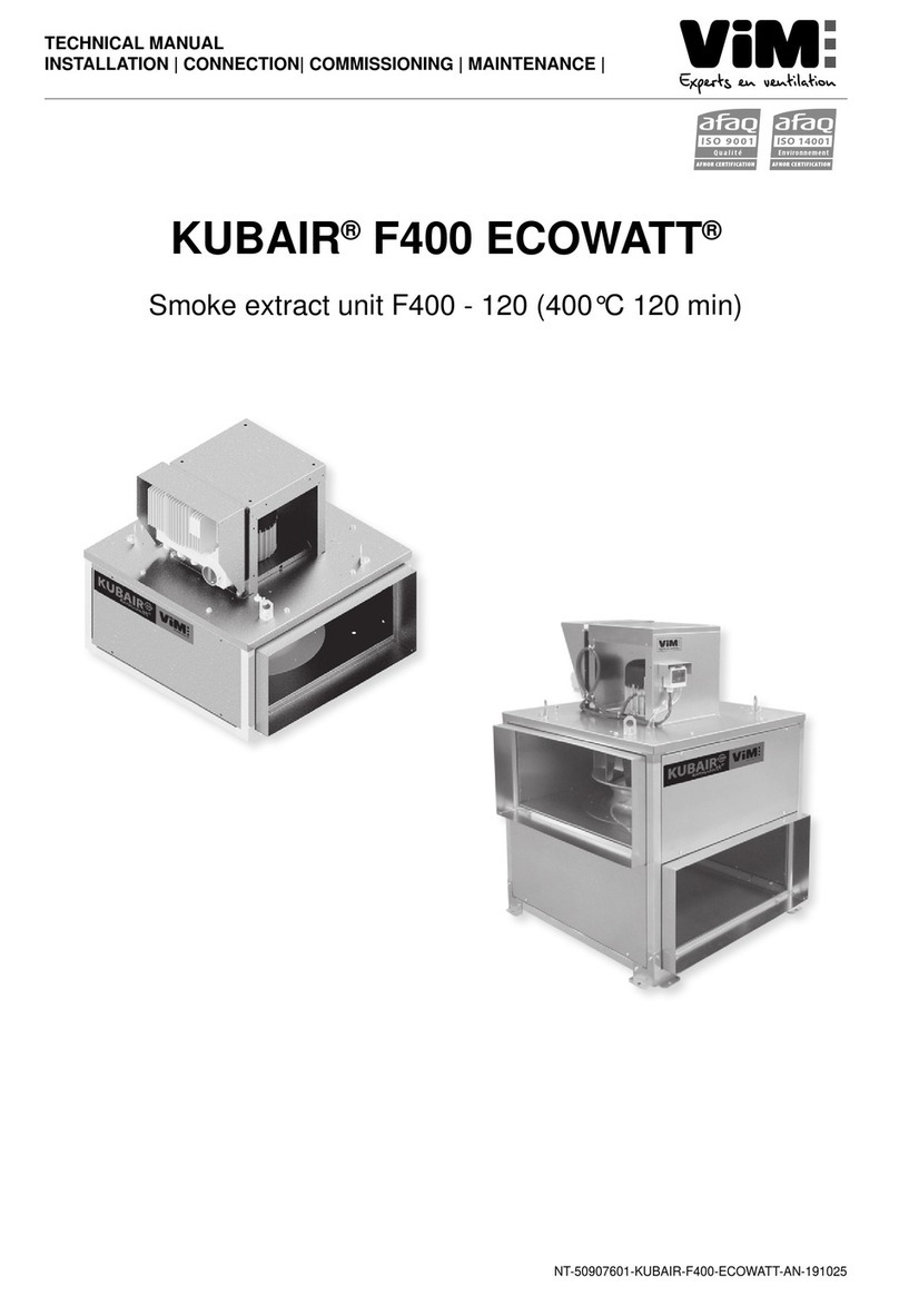
ViM KUBAIR F400 User manual

NT-50907501-KUBAIR-F400-AN-210312
INSTRUCTION MANUAL
INSTALLATION | WIRING | COMMISSIONING | MAINTENANCE |
AFNOR CERTIFICATION
ISO 14001
Environnement
AFNOR CERTIFICATION
ISO 9001
Qualité
KUBAIR®F400
Smoke extract unit F400 - 120 (400°C 120 min)

NT-50907501-KUBAIR-F400-AN-2103122/28
ENGLISH
INDEX
1. GENERAL........................................................................................................................................... 3
1.1 Warnings .................................................................................................................................. 3
1.2 Safety instructions.................................................................................................................... 3
1.3 Acceptance – Storage.............................................................................................................. 3
1.4 Warranty................................................................................................................................... 4
2. PRODUCT PRESENTATION ............................................................................................................. 4
3. INSTALLATION .................................................................................................................................. 4
3.1 Dimensions and weight (mm)................................................................................................... 5
3.2 Summary charts of assembly and accessories........................................................................ 7
3.3 Accessories (dimensions in mm)............................................................................................ 10
3.4 Handling ................................................................................................................................. 17
3.5 Casing assembly.................................................................................................................... 17
4. ELECTRICAL CONNECTION.......................................................................................................... 18
4.1 Preliminary precautions.......................................................................................................... 18
4.2 Technical Characteristics........................................................................................................ 18
4.3 Wiring of versions without INTZ safety switch........................................................................ 20
4.4 Wiring of versions with INTZ safety switch............................................................................. 21
4.5 Wiring of PILOTAIR®control panel (French regulation) ......................................................... 23
4.6 Electrical connection of pressure switch................................................................................. 23
5. START-UP ........................................................................................................................................ 24
6. MAINTENANCE................................................................................................................................ 24
6.1 Maintenance periodicity.......................................................................................................... 24
6.2 Spare parts KUBAIR®F400.................................................................................................... 25
7. WASTE MANAGEMENT.................................................................................................................. 27
7.1 Treatment of Packagings and non dangerous wastes ........................................................... 27
7.2 Treatment of a Professional WEEE........................................................................................ 27

NT-50907501-KUBAIR-F400-AN-2103123/28
ENGLISH
1. GENERAL
1.1 Warnings
This product was manufactured according to rigorous technical safety rules in compliance with EC stan-
dards. The EC declaration and the manual can be downloaded from the Internet (address given on the
last page).
Before installing and using this product, carefully read these instructions, which contain important indications to
ensureyoursafetyandtheuser’ssafetyduringtheinstallation,commissioningandmaintenanceofthisproduct.
Once the installation is terminated, keep this manual handy nearby the machine for future consultation.
The installation of this product (implementation, connections, commissioning, maintenance) and all other
interventions must be performed by a professional applying the recognized rules of good practice, stan-
dards and safety regulations in force.
It must conform to the prescriptions related to Electromagnetic Compatibility (EMC) and the Low Voltage
Directive (LV).
VIM shall not be held responsible for possible injuries and/or damages caused by the non compliance with
safety instructions or following a modication of the product.
The smoke extract units KUBAIR®F400 are intended for smoke extraction and ventilation applications in
residential buildings, tertiary buildings, industrial buildings and professional kitchens:
• Outdoor installation.
• Environmental temperature range: -20°C / +40°C.
• Max temperature of extracted air in permanent operation: 120°C.
• Relative humidity: max 95% non-condensing.
• Atmosphere not potentially explosive.
• Low salinity atmosphere, with no corrosive chemical agents.
1.2 Safety instructions
• Wear appropriate IPE (Individual Protection Equipment) before any intervention.
• Before installing the smoke extract unit, make sure that the support and placement are suciently
resistant to withstand the unit’s weight and that of the accessories.
• Do not open the access doors without rst switching o the electrical power supply with the padloc-
kable mains power switch present on the unit.
• If the work is to be performed inside the device, switch o the electrical power supply on the main
circuit breaker and make sure that no one can accidentally switch it on.
• Make sure that the moving parts are stopped.
• Make sure that the motor driven fans are not accessible from the connection taps (connection duct
or screened protection).
Before starting, check the following points :
• Make sure that the device does not contain any foreign body.
• Make sure that all the components are attached in their original placements.
• Check manually that the fans do not rub or are not blocked.
• Make sure that the rotating heat exchanger is not blocked.
• Check the earthing connection.
1.3 Acceptance – Storage
In case of missing, non-conforming, or totally or partially damaged delivered products, the Purchaser must
make written reservation on the transporter’s receipt and conrm them within seventy-two (72) hours by
sending a recommended letter to the transporter, as well as a copy to VIM. Acceptance of the equipment
without any reservation will deprive the Purchaser of any subsequent recourse against us.
The product must be stored in an area protected from bad weather, shocks and stains due to splashings
or splatterings of any kind during its transport from the supplier to the end customer and onto the worksite
before installation.
NT-50907501-KUBAIR-F400-AN-2103124/28
ENGLISH
1.4 Warranty
The equipment is guaranteed for 24 months from the invoice date. The warranty is limited to the replacement
of parts or equipment whose operation is recognized as defective by maker, excluding any compensation or
penalties. The costs of labor, removal and rest, travel related to the replacement are the responsibility of the
Customer. Excluded from our warranty are defects linked to abnormal use or not in accordance with the re-
commendations in our instructions, defects observed as a result of normal wear and tear, incidents caused by
negligence, lack of monitoring or maintenance, defects due to incorrect installation of devices or poor storage
conditions prior to assembly.
In any case, maker is not responsible for transformed material, even partially repaired.
2. PRODUCT PRESENTATION
CE certicate F400 -120 No. 1812-CPR-0040, according to European Standard NF EN 12101-3
F400 120 approved (400 °C 120 min)
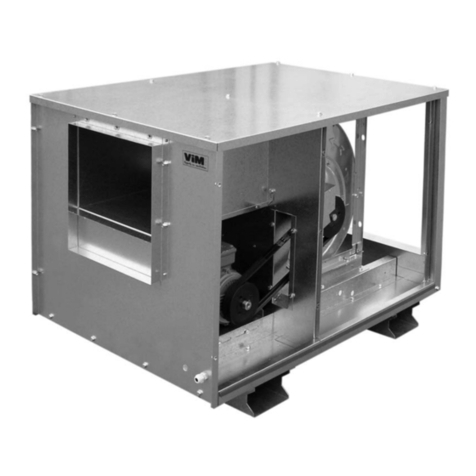
• KUBAIR®F400 CC: complete unit with multi-directional suction
plenum, with horizontal or vertical axis motor.
• KUBAIR®F400 MV: single ventilation unit, with horizontal or vertical
axis motor.
• 8 sizes: 355 / 400 / 450 / 500 / 560 / 630 / 710 / 800.
• Flow of 500 to 23 000 m3/h.
Construction
• Removable galvanised steel sheet panels.
• Modular structure with aluminium frame.
• Connection by 2 KUBZ 12 smooth anges which are included.
• High performance galvanised steel reaction turbine, mounted by direct coupling with the motor.
Motorisation
• Standard B5 ange motor, IP 55, class F.
• Optional PTO thermal protection.
• 230V 50Hz single-phase with 1 speed and 2, 4 or 6 poles; accepts voltage variation.
• 230/400V 50Hz three-phase with 1 speed and 2, 4, 6 or 8 poles, IE1, IE2 or IE3; accepts frequency
variation.
• 400V 50Hz three-phase with 2 speeds and 4/6, 4/8, 6/8 or 6/12 poles, Dahlander or separate
windings.
Kitchen Option
The kitchen option includes a reinforced seal of the casing, double skin panel (insulation option) and a
drain to carry away wash water. The drain should be installed at the bottom of the casing to allow the wash
water to be eectively discharged.
3. INSTALLATION

NT-50907501-KUBAIR-F400-AN-2103125/28
ENGLISH
3.1 Dimensions and weight (mm)
KUBAIR
®
F400 MV
Assembly with horizontal motor axis
A
BH
F
C
D
E
K
J
Tipping risk during
handling operations
Assembly with vertical motor axis
56
A
L
BV
D
A
C
G
KUBAIR
®
F400 CC
Assembly with horizontal motor axis
A
BH
F
D
J
C
EC
KC
Assembly with vertical motor axis
55
A
C
H
C
L
BVC
GC
A
C
D
Size A BH BV BVC C D E EC F G GC H J K KC L
355
627 695 327 645 263 559 606 790 660 31 50 315 102 677 954 321
400
699 767 361 678 297 631 606 864 732 31 50 349 102 711 1022 321
450
779 847 392 738 326 711 606 990 812 31 50 378 102 743 1081 321
500
858 925 424 784 338 768 700 1039 890 42 62 402 112 805 1145 351
560
954 1021 441 817 354 864 700 1139 986 42 62 419 112 822 1178 351
630
1066 1133 488 912 403 977 700 1183 1098 42 62 466 112 869 1273 351
710
1194 1261 551 1032 462 1104 906 1325 1226 42 62 526 112 994 1488 446
800
1338 1420 574 1084 488 1248 906 1379 1370 42 62 552 127 1050 1540 446

NT-50907501-KUBAIR-F400-AN-2103126/28
ENGLISH
Model Rated P. (kW) Weights (kg)
MV Naked/
Insulated
Weights (kg)
CC Naked/
Insulated Model Rated P.
(kW) Weights (kg)
MV Naked/
Insulated
Weights (kg)
CC Naked/
Insulated
MOTOR 1 SPEED 1 PHASE 4 POLES MOTOR 2 SPEEDS TRI - BOB. IND. 4/6 P
355 0,25 39/42 59/65 355 0,3/0,1 41/44 61/67
400 0,55 49/53 72/80 400 0,55/0,2 51/55 74/82
MOTOR 1 SPEED 1 PHASE 6 POLES 450 1,1/0,3 69/74 94/104
355 0,18 39/42 59/65 500 1,5/0,37 90/96 116/128
400 0,25 49/53 72/80 560 2,2/0,7 113/120 161/175
450 0,25 67/72 92/102 MOTOR 2 SPEEDS TRI - BOB. IND. 6/8 P
500 0,37 88/94 114/126 450 0,37/0,2 69/74 94/104
MOTOR 1 SPEED 3 PHASES 4 POLES 500 0,55/0,37 90/96 116/128
355 0,25 39/42 59/65 560 0,75/0,37 113/120 161/175
400 0,55 49/53 72/80 630 1,1/0,55 120/125 164/182
450 1,1 67/72 92/102 710 3/0,75 146/155 266/290
500 1,5 88/94 114/126 800 4/1,1 226/238 309/337
560 2,2 111/118 159/173 MOTOR 2 SPEEDS TRI - BOB. DAHL. 4/8 P
MOTOR 1 SPEED 3 PHASES 6 POLES 355 0,6/0,15 41/44 61/67
355 0,18 39/42 59/65 400 0,6/0,15 51/55 74/82
400 0,37 49/53 72/80 450 1,2/0,3 69/74 94/104
450 0,37 67/72 92/102 500 1,6/0,4 90/96 116/128
500 0,55 88/94 114/126 560 2,2/0,55 113/120 161/175
560 0,75 111/118 159/173 MOTOR 2 SPEEDS TRI - BOB. DAHL. 6/12 P
630 1,1 118/125 162/180 630 1,1/0,22 120/125 164/182
710 3,0 144/153 264/288 710 4/1 146/155 266/290
800 4,0 224/236 307/335 800 4/1 226/238 309/337
MOTOR 1 SPEED 3 PHASES 8 POLES
450 0,18 68/73 93/103
500 0,18 89/95 115/127
560 0,37 112/119 160/174
630 0,55 119/124 163/181
710 2,2 145/154 265/289
800 2,2 225/237 308/336

NT-50907501-KUBAIR-F400-AN-2103127/28
ENGLISH
3.2 Summary charts of assembly and accessories
KUBAIR
®
F400 CC
MSDZ
KUBZ 04 straight
MSCZ
KUBZ 12
KUBZ 06
KUBZ 02
KUBZ 08
KUBZ 10
KUBZ 12
KUBZ 17
KUBZ 06
KUBZ 15 CC
KUBZ 01 CC
KUBZ 16
KUBZ 12
KUBZ 07
KUBZ 10
KUBZ 04 straight

NT-50907501-KUBAIR-F400-AN-2103128/28
ENGLISH
KUBAIR
®
F400 MV
KUBZ 08
KUBZ 10
KUBZ 17
KUBZ 12
KUBZ 03
KUBZ 11
KUBZ 12
KUBZ 08
KUBZ 03
KUBZ 06
KUBZ 03
KUBZ 15 MV
KUBZ 01 MV
KUBZ 16
KUBZ 10
KUBZ 07
The TCDZ accessories on the diagram below can
be used with the KUBAIR®F400 MV with a vertical
axis motor: (example opposite side).

NT-50907501-KUBAIR-F400-AN-2103129/28
ENGLISH
KUBAIR
®
F400 MV
with vertical axis motor
TCDZ05*
TCDZ03
TCDZ03
SIL
TCDZ 04 TCDZ 07 TCDZ 02 TCDZ 09
or
or
or or
Optional accessory according to selection.
TCDZ08

NT-50907501-KUBAIR-F400-AN-21031210/28
ENGLISH
3.3 Accessories (dimensions in mm)
Circular exible spool piece Rectangular exible spool piece
E
Ø F
E
A+3
B+3
AB
B
A
C
Standard support for horizontal axis motor:
This support means that the casing can be attached
to the oor with the motor in a horizontal position
(horizontal axis). The 2 support arms are attached
to the casing by the 4 M8 x 15 screws which are
supplied, and the 4 stands are attached to the arms by
the 16 self-drilling 4.8 x 12 screws which are supplied.
If the casing comes with a PILOTAIR®control panel
(French regulation), this must be detached and then
re-assembled onto the vertical wall of the motor cowl.
Mounting holes are provided so that it can be re-
assembled using the self-drilling screws.
A
B
Connecting ange
This connecting ange is attached to the smooth
ange at its 4 corners for the purpose of attaching
a duct.
A
A
ØF
Circular connection to the MV suction horizontal
motor axis:
This connection is used with the KUBAIR®F400 MV
for a duct connection which does not have a roof
adapter and which must not bear the weight of the
casing.
A+3
B+3
H
ØF
ØF
A+3
B+3
H
Rigid circular connection
ØA
H
S
G
Fz
B
C
d
ØA
H
S
G
Fz
B
C
d
Antivibration pads
4 Antivibration pads are supplied with 4 screws to
attach them to the casing.
AB
C
KUBAIR® cowl
The motor cowl is used for external installations. It is
screwed (screws supplied) onto the motor support
panel.
MSDZ MSCZ
KUBZ 01
KUBZ 02
KUBZ 03
KUBZ 04
KUBZ 05
KUBZ 06

NT-50907501-KUBAIR-F400-AN-21031211/28
ENGLISH
C
A
B
D
B
A
Rain guard with bird guard
These guards are attached after the supplied
smooth ange (KUBZ 12) has been detached from
the casing.
K
A
B
F
O
Manual ow control damper
Attaches to the discharge using the 4 bolts supplied.
Allows to reduce and adjust the airow.
KUBZ 10 air performance are shown here below.
C
AA
B
ØD
75 75
EØ12
Double suction plenum
Tobeboltedunderthecasing,withoutanyaccessory
between the KUBZ 11 and the casing.
A
B
J
Smooth ange for spool piece
2 smooth anges are supplied already mounted on
the air delivery and suction. Other smooth anges
can be supplied and mounted.
AB
B
A
C
Covering (necessary for external use) -
horizontal axis motor
Assembly of the cover: the cover is attached with 4
(MV version) or 8 (CC version) 4.8 x 12 self-drilling
screws which are supplied.
J
A
BOver-pressure aps to be mounted on the
discharge side for horizontal shaft motor
Ensures good water and air tightnass when the
unit is stopped.
Supplied with 4 bolts for xing to the unit. Install
one KUBZ 16 per discharge side.
J
A
B
Over-pressure aps to be mounted on the
discharge side for vertical shaft motor
Ensures good water and air tightness when the
unit is stopped.
Supplied with 4 bolts for xing to the unit. Install
one KUBZ 17 per discharge side.
KUBZ 08
KUBZ 07
KUBZ 10
KUBZ 11
KUBZ 12
KUBZ 15
KUBZ 16
KUBZ 17

NT-50907501-KUBAIR-F400-AN-21031212/28
ENGLISH
Dimensions (mm) and weight (kg)
KUBZ 11
Size A B C ØD E Weight (kg)
355 622 448 238 355 662 21
400 694 498 260 400 734 25
450 774 555 289 450 814 30
500 852 675 349 560 892 37
560 948 755 389 630 988 60
630 1060 805 441 630 1100 81
710 1188 885 481 710 1228 99
KUBZ 10 Air performances
The airow adjustment of a KUBZ 10 depends on the initial pressure airow running point, fan speed.
KUBAIR F400 MV 355 KUBAIR F400 MV 400
Plage d’utilisation KUBZ10
0
100
200
300
400
500
600
700
0
50
100
150
200
250
300
350
0 500 1000 1500 2000 2500 3000 3500 4000
Pabs (W)∆Pstat (Pa)
Qv (m3/h)
4 pôles
39
74
6 pôles
8 pôles
6 pôles
8 pôles
37
37
28
28
31
24
22
22
71
63 62
58
56
56 65
70
4 pôles
4 poles
6 poles
6 poles
8 poles
8 poles
KUBZ 10 airow adjustment range
4 poles
0
200
400
600
800
1000
0
100
200
300
400
500
0 1000 2000 3000 4000 5000 6000
Pabs (W)∆Pstat (Pa)
76
4 pôles
41
6 pôles
8 pôles
8 pôles
41
44
35
26
29
41
77
80
65
61
61
68
67
Qv (m3/h)
42 6 pôles
Plage d’utilisation KUBZ10
71
4 pôles
26
KUBZ 10 airow adjustment range
8 poles
8 poles
6 poles
6 poles
4 poles
4 poles
MSDZ - MSCZ - KUBZ 02 to 08 - KUBZ 10, 12, 16 and 17 Weight (kg)
Model A B C D E ØF H J K KUBZ
01 KUBZ
03 KUBZ
04 KUBZ
06 KUBZ
07 KUBZ
08
355 559 263 197 194 160 400 670 80 224 7.0 2.9 7.5 3.6 1.9 2.0
400 631 297 216 213 160 450 670 80 237 8.2 3.5 8.5 3.6 2.4 2.4
450 711 326 233 234 160 500 670 80 245 9.7 4.2 9.6 3.6 2.8 2.8
500 768 338 240 249 160 560 670 80 256 10.6 4.6 10.5 5.4 3.1 3.1
560 864 354 250 275 160 630 670 80 267 11.9 5.6 11.6 5.4 3.7 3.5
630 977 403 278 305 160 710 670 80 302 13.8 6.9 13.2 5.4 4.5 4.3
710 1104 462 311 340 160 800 670 80 343 17.0 8.3 15.1 6.9 5.6 5.3
800 1248 488 328 378 160 900 670 80 361 19.6 10.2 17.0 6.9 6.8 6.1
Size KUBZ 05 KUBZ 06
A C H G B d S Screws supplied A B C
355 to 450 60 90 24 M6 76 62 3 M6x16 340 325 305
500 to 630 80 120 27 M8 100 82 3 M8x15 415 475 355
710 to 800 100 148 28 M10 124 102 3 M10x15 510 465 450

NT-50907501-KUBAIR-F400-AN-21031213/28
ENGLISH
KUBAIR F400 MV 450 KUBAIR F400 MV 500
0
200
400
600
800
1000
1200
1400
0
100
200
300
400
500
600
700
0 1000 2000 3000 4000 5000 6000 7000 8000
Pabs (W)∆Pstat (Pa)
Qv (m3/h)
80
4 pôles
4 pôles
46
6 pôles
8 pôles
6 pôles
8 pôles
46
48
40
37
33
31
37
31
80
82
71
71
65 65 67
Plage d’utilisation KUBZ10
74
KUBZ 10 airow adjustment rang
8 poles
8 poles
6 poles
4 poles
4 poles
6 poles
0
300
600
900
1200
1500
1800
2100
2400
0
100
200
300
400
500
600
700
800
0 1000 2000 40003000 5000 6000 7000 8000 100009000
Pabs (W)∆Pstat (Pa)
Qv (m3/h)
82
4 pôles
48
6 pôles
8 pôles 6 pôles
8 pôles
82
83
75
74
68
67
67
73
49
50
40
40
41
35
34
33
Plage d’utilisation KUBZ10
4 pôles
KUBZ 10 airow adjustment rang
8 poles
8 poles
6 poles
4 poles
4 poles
6 poles
KUBAIR F400 MV 560 KUBAIR F400 MV 630
0
500
1000
1500
2000
2500
3000
3500
4000
4500
5000
0
100
200
300
400
500
600
700
800
900
1000
0 2000 4000 6000 8000 10000 12000 14000
Pabs (W)∆Pstat (Pa)
Qv (m3/h)
84
4 pôles
50
49
50
42
40
41
35 34
35
83
85
76
75
75
69
68 70
6 pôles
8 pôles
6 pôles
8 pôles
Plage d’utilisation KUBZ10
4 pôles
KUBZ 10 airow adjustment range
4 poles
6 poles
8 poles
8 poles 6 poles
4 poles
0
300
600
900
1200
1500
1800
0
100
200
300
400
500
600
0 2000 4000 6000 8000 10000 12000
Pabs (W)∆Pstat (Pa)
Qv (m3/h)
77
6 pôles
6 pôles
45
8 pôles
12 pôles 8 pôles
12 pôles
78
79
73
72
64
63
71
62
47
30 41
39
32
31
47
Plage d’utilisation KUBZ10
40
KUBZ 10 airow adjustment range
8 poles
6 poles
8 poles
12 poles
12 poles
6 poles
KUBAIR F400 MV 710 KUBAIR F400 MV 800
0
400
800
1200
1600
2000
2400
2800
3200
0
100
200
300
400
500
600
700
800
0 5000 10000 15000 20000
Pabs (W)∆Pstat (Pa)
Qv (m3/h)
6 pôles
6 pôles
54
8 pôles
12 pôles
8 pôles
12 pôles
54
48
39 39
40
83
84
78
76
76
67 67 69
49
56
Plage d’utilisation KUBZ10
82
48
KUBZ 10 airow adjustment range
12 poles
12 poles
8 poles
6 poles
6 poles
8 poles
0
1000
2000
3000
4000
5000
6000
7000
8000
9000
1000
0
0
100
200
300
400
500
600
700
800
900
10
00
0500010000 1500020000 25000
Pabs (W)∆Pstat (Pa)
Qv (m3/h)
84
6 pôles
56
8 pôles
12 pôles
8 pôles
12 pôles
85
86
79
78
78
69 70 70
56
56
50
49
41 41 41
6 pôles
Plage d’utilisation KUBZ10
49
KUBZ 10 airow adjustment range
6 poles
8 poles
12 poles
12 poles
8 poles
6 poles
KUBAIR F400 CC 355 KUBAIR F400 CC 400
0
100
200
300
400
500
600
700
Pabs (W)
0
50
100
150
200
250
300
350 ∆Pstat (Pa)
0 500 1000 1500 2000 2500 3000 3500
Qv (m3/h)
72 41
60 66
29
35
6 pôles
8 pôles
26
57
54 24
30
60 4 pôles
6 pôles
8 pôles
44
75
39
69
Plage d’utilisation KUBZ10
4 pôles
32
63
KUBZ 10 airow adjustment range
8 poles
6 poles
4 poles
8 poles
6 poles
4 poles
0
200
400
600
800
1000
0
100
200
300
400
500
0 1000 2000 3000 4000 5000 6000
Pabs (W)
∆Pstat (Pa)
Qv (m3/h)
6 pôles
8 pôles
4 pôles
4 pôles
44
76
6 pôles
8 pôles
73
67
65
58 60 64 79
42
33
27 29
33 39 48
35
Plage d’utilisation KUBZ10
71
KUBZ 10 airow adjustment range
8 poles
6 poles
4 poles
6 poles
4 poles
8 poles

NT-50907501-KUBAIR-F400-AN-21031214/28
ENGLISH
KUBAIR F400 CC 450 KUBAIR F400 CC 500
0
200
400
600
800
1000
1200
1400
0
100
200
300
400
500
600
700
0 1000 2000 3000 4000 5000 6000 7000 8000
Pabs (W)∆Pstat (Pa)
Qv (m3/h)
6 pôles
4 pôles
53
83
6 pôles
8 pôles
8 pôles
4 pôles
80
78
69
71
74
68
65
63
50
48
44
38
39
35
33
Plage d’utilisation KUBZ10
41
KUBZ 10 airow adjustment range
4 poles
4 poles
6 poles
8 poles
8 poles
6 poles
0
300
600
900
1200
1500
1800
2100
2400
0
100
200
300
400
500
600
700
800
0 1000 2000 3000 4000 5000 6000 7000 8000 9000 10000
Pabs (W)∆Pstat (Pa)
Qv (m3/h)
6 pôles
4 pôles
52
85
6 pôles
8 pôles
8 pôles
44
41
47
37
34
39
32
82
80
73
76
70
67
71
65
49
Plage d’utilisation KUBZ10
4 pôles
4 poles
KUBZ 10 airow adjustment range
6 poles
8 poles
8 poles
6 poles
4 poles
KUBAIR F400 CC 560 KUBAIR F400 CC 630
0
500
1000
1500
2000
2500
3000
3500
4000
4500
5000
0
100
200
300
400
500
600
700
800
900
1000
0 2000 4000 6000 8000 10000 12000
Pabs (W)∆Pstat (Pa)
Qv (m3/h)
4 pôles
52
87
6 pôles
8 pôles
6 pôles
8 pôles
43
40
37
34
38
49
32
47
78
83
75
72
68
67
73
82
Plage d’utilisation KUBZ10
4 pôles
4 poles
KUBZ 10 airow adjustment range
4 poles
6 poles
8 poles
8 poles
6 poles
Plage d’utilisation KUBZ10
0
300
600
900
1200
1500
1800
0
100
200
300
400
500
600
0 2000 4000 6000 8000 10000 12000
Pabs (W)∆ Pstat (Pa)
Qv (m3/h)
6 pôles
6 pôles
49
82
8 pôles
12 pôles
8 pôles
12 pôles
45
44
38
39
43
34
30
29
78
77
70
76
67
63
62
72
KUBZ 10 airow adjustment range
12 poles
6 poles
8 poles
6 poles
8 poles
12 poles
KUBAIR F400 CC 710 KUBAIR F400 CC 800
Plage d’utilisation KUBZ10
0
400
800
1200
1600
2000
2400
2800
3200
0
100
200
300
400
500
600
700
800
0 5000 10000 15000 20000
Pabs (W)∆Pstat (Pa)
Qv (m3/h)
6 pôles
6 pôles
54
85
8 pôles
12 pôles
8 pôles
12 pôles
51
52
44
48
39
37
35
82
76
79
70
67
66
75
81
46
KUBZ 10 airow adjustment range
12 poles
12 poles
6 poles
8 poles
8 poles
6 poles
Plage d’utilisation KUBZ10
0
1000
2000
3000
4000
5000
6000
7000
8000
9000
10000
0
100
200
300
400
500
600
700
800
900
1000
0 5000 10000 15000 20000 25000
Pabs (W)∆Pstat (Pa)
Qv (m3/h)
6 pôles
6 pôles
56
84
8 pôles
12 pôles
8 pôles
12 pôles
54
54
48
49
40
39
39
82
83
78
76
76
69
67
67
48
KUBZ 10 airow adjustment range
8 poles
6 poles
8 poles
6 poles
12 poles
12 poles

NT-50907501-KUBAIR-F400-AN-21031215/28
ENGLISH
E
G
S
Sealing frame
Embed the frame into the constructed support and make
sure that the xing lugs are embedded into the concrete.
A mini
70 mm
E
G
M
K
Energy-saving component
Assemble theenergy-saving component insidethe upstands,
under the casing. It is incompatible with the use of the TCDZ
05 adapter plates. Make sure that the components are able
to move freely before the casing is assembled. Take into
account 50Pa pressure drop.
Straight, inclined and acoustic upstand
According to DTU 43.1, it is possible to attach a TCDZ 03
energy-saving component or a TCDZ 05 (excluding TCDZ
09) adapter plate which is placed inside the upstand.
For any casing with an acoustic straight upstand (TCDZ
09). Take into account 80Pa pressure drop.
E
G
150
100
100
α
100
G
N
E
R
E
G
N
800
100
G
E
ØD
T
TCDZ 05: Adapter plate
The adapter plate allows to connect the casing to a circular
duct. This part allows the aeraulic connection and it is not
intended to bear the weight of the casing. It is incompatible
with the use of the TCDZ 03 energy-saving component and
the TCDZ 09 acoustic upstand.
TCDZ 02
TCDZ 03
TCDZ 07TCDZ 04
TCDZ 09
TCDZ 05

NT-50907501-KUBAIR-F400-AN-21031216/28
ENGLISH
200
G
E
200 mm upstand lift
Allows to increase the height of the casing by 200 mm,
allows to insert a TCDZ 05 adapter plate between the
casing and the TCDZ 03 energy-saving component or to
mount a TCDZ 03 energy-saving component onto a TCDZ
02 sealing frame.
Roof
adapter
Adapter
plate
Energy saving
ap
Roof adapter
heightener
A
E
E
G
Ø19
Ø12
J
Sound absorber
Take into account 80Pa pressure drop.
DRAIN (KITCHEN OPTION)
To install the drain at the bottom of the casing, make a 22 mm hole, position the drain with its seal and
attach it with 2 3.5 x 19 screws (recommendation, screws not supplied).
Accessory TCDZ 02 TCDZ 03 TCDZ 05 SILS
Size Weight (Kg) Weight (Kg) ØD Weight (Kg) Weight (Kg)
355/400 2.5 5.0 315/355/400/450* 1.8/1.5/1.2/0.8 23.0
450/500 4.0 6.0 400/450/500/560* 3.6/3.1/2.5/1.7 37.0
560/630 4.5 8.0 450/500/560/630 5.1/4.5/3.7/2.7 45.0
710/800 6.0 11.0 560/630/710 11.8/10.3/8.3 65.0
Accessory TCDZ 04 TCDZ 07 (30°) TCDZ 09 TCDZ 08
Size R Weight (Kg) Weight (Kg) Weight (Kg) Weight (Kg)
355/400 300/500/700 11.0/15.5/20.0 11.2 34.0 6.2
450/500 300/500/700 13.5/19.0/25.0 14.8 51.0 10.5
560/630 300/500/700 20.5/29.5/38.0 24.2 65.5 12.2
710/800 300/500/700 25.5/37.0/48.0 32.4 90.5 15.0
Casing size Accessory size A E G J S
355/400 2 540 450 478 630 30
450/500 3 660 570 598 700 40
560/630 4 800 668 698 700 40
710/800 5 930 830 866 700 40
Casing size Accessory size M N K R Ø D T
355/400 2 145 678 400 300/500/700 315/355/400/450* 50/65/80/80
450/500 3 170 798 490 300/500/700 400/450/500/560* 80/80/80/80
560/630 4 170 898 605 300/500/700 450/500/560/630 80/80/80/90
710/800 5 190 1066 730 300/500/700 560/630/710 80/90/120
* These adapter plates can only be mounted with the following accessories: TCDZ02, 04, 07 and 08
TCDZ 08
SILS

NT-50907501-KUBAIR-F400-AN-21031217/28
ENGLISH
3.4 Handling
To keep people safe or prevent damage to property, use compliant
handling equipment that is in a good condition.
The casing must be lifted at the 4 lifting lugs.
Use slings with a length that is at least double the width of the casing.
Makesurethattheslingsdonotrubagainstthemotorcowlortheelectrical
accessories.
If in doubt, detach it to avoid any damage.
3.5 Casing assembly
The support surface that will support the base of the casing must be as at as possible (sealing frame
or roof adapter supplied on demand). A seal of foam or similar material (not supplied) is recommended
between the support surface and the base of the casing. A maximum incline of 2.5° is tolerated between
the motor axis and the vertical axis (see diagram below).
2,5°
Make sure that the support is adapted to the weight
of the whole machine and its various accessories.
Attach the casing at the Ø20 holes provided for
this purpose. You are advised to use a LL washer.
Any screws that are not properly tightened may
make noises and cause harmful vibrations. Once
the machine has been correctly set up, make sure
that the motor turbine is able to rotate freely without
any friction or noise. Vibration isolating devices are
available: KUBZ 05.
Detaching and re-assembling casing panels
The smooth side panels are easy to detach by
loosening their screws. They are repositioned in the
same way.

NT-50907501-KUBAIR-F400-AN-21031218/28
ENGLISH
4. ELECTRICAL CONNECTION
4.1 Preliminary precautions
Electrical connections must be set up by qualied sta. Do not forget the earthing connection.
In addition, the cables routing must be protected from mechanical aggressions when the connection is
made to the motor’s terminal box or to the unit’s safety switch.
If used for comfort application, the electric motor must be protected by a suitable magnetothermal protec-
tion device.
WARNING: before performing any operations, make sure that there is no power.
Routing the power cable of the casing for any versions without INTZ or with INTZ.
Cables must be protected against any mechanical stress when they are routed.
Minimum distance = 1,5 m
Electrical accessory
added by installer
Hight temperature cable
4.2 Technical Characteristics
Model Rated
P.
(kW) Nom. I. (A)
230V Id / In Start-up
time(s) Circuit-
breaker 230V VARZ voltage
variator VAPZ coordinated
voltage variator
SINGLE-PHASE MOTOR WITH 1 SPEED AND 4 POLES
355 0.25 2.5 2.7 4 DIJZ 05 4 VARZ 3A200 VAPZ 3A200
400 0.55 3.9 3.2 3 DIJZ 05 4 VARZ 6A200 VAPZ 5A200
SINGLE-PHASE MOTOR WITH 1 SPEED AND 6 POLES
355 0.18 1.6 1.8 3 DIJZ 05 2.5 VARZ 3A200 VAPZ 3A200
400 0.25 2.3 2.0 2 DIJZ 05 2.5 VARZ 3A200 VAPZ 3A200
450 0.25 2.3 2.0 6 DIJZ 05 2.5 VARZ 3A200 VAPZ 3A200
500 0.37 3.0 2.0 6 DIJZ 05 4 VARZ 6A200 VAPZ 5A200
Model Rated
P.
(kW)
Eciency
category Nom. I.
(A)
230V
Nom. I.
(A)
400V Id / In Start-up
time(s) VFTM Mono
calibre
(kW)
VFTM Tri
calibre
(kW)
VFKB Mono
Calibre
(kW)
VFKB Tri
Calibre
(kW)
THREE-PHASE MOTOR WITH 1 SPEED AND 4 POLES
355 0.25 IE1 1.4 0.81 3.5 3 0.37 0.37 0.37 0.37
355 0.25 IE2 1.36 0.78 4.5 3 0.18 0.37 0.37 0.37
355 0.25 IE3 1.22 0.70 4.5 3 0.18 0.37 0.37 0.37
400 0.55 IE1 2.47 1.42 4.7 3 0.37 0.55 0.55 0.37
400 0.55 IE2 2.28 1.31 6.0 2 0.37 0.37 0.55 0.37
400 0.55 IE3 2.17 1.25 6.6 2 0.37 0.37 0.37 0.37

NT-50907501-KUBAIR-F400-AN-21031219/28
ENGLISH
Model Rated
P.
(kW)
Eciency
category Nom. I.
(A)
230V
Nom. I.
(A)
400V Id / In Start-up
time(s) VFTM Mono
calibre
(kW)
VFTM Tri
calibre
(kW)
VFKB Mono
Calibre
(kW)
VFKB Tri
Calibre
(kW)
450 1.1 IE2 4.33 2.49 6.5 3 0.75 1.1 0.75 0.75
450 1.1 IE3 4.07 2.34 7.6 2 0.75 1.1 0.75 0.75
500 1.5 IE2 5.67 3.26 6.3 3 1.1 1.5 1.1 1.1
500 1.5 IE3 5.48 3.15 7.4 3 1.1 1.5 1.1 1.1
560 2.2 IE2 8.29 4.80 7.0 3 2.2 2.2 2.2
560 2.2 IE3 7.93 4.56 7.4 3 2.2 2.2 2.2
THREE-PHASE MOTOR WITH 1 SPEED AND 6 POLES
355 0.18 IE1 1.28 0.74 3.3 2 0.18 0.37 0.37 0.37
355 0.18 IE2 1.26 0.72 3.2 2 0.18 0.37 0.37 0.37
355 0.18 IE3 1.21 0.70 3.2 2 0.18 0.37 0.37 0.37
400 0.37 IE1 1.97 1.13 3.6 2 0.37 0.37 0.37 0.37
THREE-PHASE MOTOR WITH 1 SPEED AND 6 POLES
400 0.37 IE2 1.83 1.05 3.9 2 0.37 0.37 0.37 0.37
400 0.37 IE3 1.77 1.02 4.5 2 0.37 0.37 0.37 0.37
450 0.37 IE1 1.97 1.13 3.6 4 0.37 0.37 0.37 0.37
450 0.37 IE2 1.83 1.05 3.9 4 0.37 0.37 0.37 0.37
450 0.37 IE3 1.77 1.02 4.5 4 0.37 0.37 0.37 0.37
500 0.55 IE1 2.82 1.62 0.4 5 0.37 0.55 0.55 0.37
500 0.55 IE2 2.59 1.49 4.1 4 0.37 0.55 0.55 0.37
500 0.55 IE3 2.52 1.45 4.8 4 0.37 0.55 0.55 0.37
560 0.75 IE2 3.39 1.95 4.5 5 0.55 0.75 0.55 0.55
560 0.75 IE3 3.36 1.93 5.2 5 0.55 0.75 0.55 0.55
630 1.1 IE2 4.83 2.78 4.7 5 1.1 1.1 1.1 1.1
630 1.1 IE3 4.68 2.69 4.9 5 1.1 1.1 1.1 0.75
710 3.0 IE2 12.7 7.30 5.7 6 4.0 3.0
710 3.0 IE3 12.0 6.91 6.0 6 4.0 3.0
800 4.0 IE2 16.5 9.46 6.0 7 5.5
800 4.0 IE3 15.6 8.99 6.5 7 5.5
THREE-PHASE MOTOR WITH 1 SPEED AND 8 POLES
450 0.18 IE1 1.50 0.86 2.8 4 0.37 0.37 0.37 0.37
450 0.18 IE2 1.26 0.73 3.1 4 0.18 0.37 0.37 0.37
450 0.18 IE3 1.19 0.68 3.3 4 0.18 0.37 0.37 0.37
500 0.18 IE1 1.50 0.86 2.8 6 0.37 0.37 0.37 0.37
500 0.18 IE2 1.26 0.73 3.1 6 0.18 0.37 0.37 0.37
500 0.18 IE3 1.19 0.68 3.3 6 0.18 0.37 0.37 0.37
560 0.37 IE1 2.53 1.45 0.3 6 0.37 0.55 0.55 0.37
560 0.37 IE2 2.42 1.39 3.5 6 0.37 0.55 0.55 0.37
560 0.37 IE3 2.28 1.31 3.7 6 0.37 0.55 0.55 0.37
630 0.55 IE1 3.49 2.01 3.3 3 0.75 0.75 0.55 0.75
630 0.55 IE2 3.27 1.88 3.5 3 0.55 0.75 0.55 0.55
630 0.55 IE3 3.10 1.78 3.6 3 0.55 0.75 0.55 0.55
710 2.2 IE1 9.30 5.35 6.1 3 2.2 3.0 2.2
710 2.2 IE2 9.46 5.44 5.5 4 2.2 3.0 2.2
710 2.2 IE3 9.29 5.34 6.2 4 2.2 3.0 2.2
800 2.2 IE1 9.30 5.35 6.1 6 2.2 3.0 2.2
800 2.2 IE2 9.46 5.44 5.5 7 2.2 3.0 2.2
800 2.2 IE3 9.29 5.34 6.2 7 2.2 3.0 2.2

NT-50907501-KUBAIR-F400-AN-21031220/28
ENGLISH
Model Rated P.
GV/PV (kW) Nom. I. (A)
GV 400V Nom. I. (A)
PV 400V Id / In
GV/PV Start-up
time(s) Starter
THREE-PHASE MOTOR WITH 2 SPEEDS - SEPARATE WINDINGS 4/6 POLES
355
0.3/0.1 0.99 0.72 5/3.5 2/2 DEMZ BI 0.74/1.3
400
0.55/0.2 1.75 1.05 5/3.7 3/3 DEMZ BI 1.3/2.3
450
1.1/0.3 2.84 1.49 5.4/5.1 3/4 DEMZ BI 1.7/3.1
500
1.5/0.37 3.65 1.62 5.5/4.5 4/6 DEMZ BI 1.7/4.2
560
2.2/0.7 4.91 2.48 6/5.5 5/4 DEMZ BI 3.1/5.7
THREE-PHASE MOTOR WITH 2 SPEEDS - SEPARATE WINDINGS 6/8 POLES
450
0.37/0.2 1.40 0.99 3.6/3.3 5/5 DEMZ BI 1.3/1.7
500
0.55/0.37 1.89 1.79 3.8/3.3 6/7 DEMZ BI 2.3/2.3
560
0.75/0.37 2.42 1.44 4.1/3.2 6/6 DEMZ BI 1.7/3.1
630
1.1/0.55 3.54 2.63 5.8/5.1 6/4 DEMZ BI 3.1/4.2
710
3/0.75 8.04 3.78 6.6/5 5/7
800
4/1.1 16.2 4.45 6.5/5 5/9
THREE-PHASE MOTOR WITH 2 SPEEDS - DAHLANDER WINDINGS 4/8 POLES
355 0.6/0.15 1.82 0.81 5.5/3.1 1/1 DEMZ DA 1/2.3
400 0.6/0.15 1.82 0.81 5.5/3.1 2/2 DEMZ DA 1/2.3
450 1.2/0.3 2.92 1.29 5.5/3.1 3/3 DEMZ DA 1.3/3.1
500 1.6/0.4 3.85 1.45 5.7/3.2 3/3 DEMZ DA 1.7/4.2
560 2.2/0.55 4.84 2.00 6.9/3.5 3/3 DEMZ DA 2.3/5.7
THREE-PHASE MOTOR WITH 2 SPEEDS - DAHLANDER WINDINGS 6/12 POLES
630
1.1/0.22 4.00 1.36 6/2.4 5/2 DEMZ DA 1.7/4.2
710 4/1 12.6 5.13 6/2.5 3/4
800
4/1 12.6 5.13 6/2.5 6/7
4.3 Wiring of versions without INTZ safety switch
Single-phase motors
One phase motor 230V
U2
U1
Z1
Z1
PE
N
Ph
Mono inlet 1S
23 0Vac50Hz
Three-phase motors with 1 speed
Three phases motor 1S
Y230 /D 400 V
Three phases inlet 1S
230Vac 50Hz 400Vac50Hz
Y230 /D 400V
Three phases motor 1S
Three phases inlet 1S
Table of contents
Other ViM Fan manuals

ViM
ViM TEDH F400 User manual

ViM
ViM KUBAIR F400 ECOWATT User manual

ViM
ViM KUBAIR F400 ECOWATT User manual

ViM
ViM JBRB ECOWATT PR User manual

ViM
ViM JBRB ECOWATT PR VCHV User manual

ViM
ViM KDTA-R F400 User manual

ViM
ViM TEDH F400 User manual

ViM
ViM TEDH F400 User manual

ViM
ViM TEDH F400 User manual

ViM
ViM KUBAIR F400 ECOWATT CC User manual
Popular Fan manuals by other brands

Brock
Brock AX12 troubleshooting guide

Home Decorators Collection
Home Decorators Collection N383B-MBK Use and care guide

Brandson
Brandson 303830 user manual

Craftsman
Craftsman Brilliante BRC52 - 4 Light installation guide

LMF Clima
LMF Clima HRH 05 Installation, operation and maintenance manual

unicraft
unicraft MV Series operating instructions