Vimar E-way 02703 User manual

Viale Vicenza, 14 - I 36063 Marostica VI
Tel. +39 0424 488 600 - Fax (Italia) +39 0424 488 188 - Fax (Export) +39 0424 488 709
www.vimar.eu
Istruzioni
E-way
02703-02704-02705-02706-02709-02710-02713-02714-02719-02720
02723-02724-02725-02726-02729-02730-02733-02734-02739-02740
CARATTERISTICHE.
• Tensione di alimentazione: 230 V~ 50 Hz
• Led verde per segnalare la presenza della tensione di rete e la ricarica della batteria.
• Led rosso per segnalare le anomalie.
• Funzionamento con batterie ricaricabili al Ni-Cd e al NiMH.
• Dispositivo di ricarica delle batterie a corrente costante.
• Dispositivo di protezione contro la scarica eccessiva della batteria.
• Possibilità di messa in stato di riposo tramite il Comando remoto per modo di riposo
02795 (opzionale).
• Corpo in materiale plastico conforme alle normative vigenti.
• Grado di protezione: IP40
• Classe di isolamento: II .
INSTALLAZIONE.
La procedura che segue deve essere effettuata esclusivamente da personale qualificato.
1) Rimuovere il diffusore facendo leva con dei cacciaviti nei punti indicati;
2) Sganciare il riflettore dalla base facendo leva con un cacciavite nel punto indicato;
3) Forare se necessario uno dei tre possibili ingressi laterali per il cavo di alimentazione
ed applicare la base al muro tramite gli appositi fori per il fissaggio;
4) Effettuare i collegamenti illustrati nelle figure 1 o 2 o 4 oppure 5;
5) Riagganciare il riflettore alla base facendo scattare il dente;
6) Riagganciare il diffusore alla base facendo scattare i denti.
Attenzione: In caso di installazione a parete il prodotto deve essere disposto
con i led verso l’alto.
BATTERIE:
La sostituzione delle batterie deve essere effettuata esclusivamente da personale qualificato.
Sostituire la batteria ogni quattro anni o quando l’autonomia non è più quella nominale.
Il tipo di batteria e la data di produzione sono indicati chiaramente sull’etichetta apposta sulla
batteria; è presente inoltre un apposito spazio che l’installatore deve compilare inserendo
la data di attivazione.
Attenzione: Le batterie al Ni-Cd e Ni-MH sono inizialmente scariche e la prima
ricarica deve durare almeno 48h.
ATTENZIONE!
Smaltire le batterie negli appositi cassonetti per la raccolta differenziata.
FUNZIONAMENTO.
• La lampada svolge la funzione di illuminazione di emergenza in caso di mancanza
di alimentazione da rete.
• Al ripristino della tensione di rete la lampada si spegnerà automaticamente ed il led
verde si accenderà.
• La ricarica della batteria avviene in modalità continua in presenza della tensione di rete.
FUNZIONI DI TEST.
• La lampada esegue tre tipi di test temporizzati: il test della batteria, il test funzionale
e il test di autonomia. I test funzionale e di autonomia possono essere effettuati anche
manualmente con il 02795 quando la batteria è in ricarica di mantenimento.
• Tutti i test manuali vengono eseguiti se esistono le condizioni ambientali idonee
di luce esterna; se esse non sono idonee, il test viene rinviato finché l’idoneità
si verifica. Durante il tempo di attesa il led verde lampeggia per segnalare che la
lampada sta aspettando di potere compiere i test.
Test della batteria: viene effettuato ogni 24 ore, è un test interno nel quale viene
controllato lo stato della batteria.
Test funzionale: viene effettuato ogni 15 giorni e consiste nella accensione della lampada
fluorescente per una durata di 5 secondi. Per attivare il test funzionale manuale premere
una volta il tasto ON del 02795 (effettuare una breve pressione per non più di 2 secondi)
Test di autonomia: viene effettuato ogni 90 giorni e consiste nella completa scarica
della batteria. Per far partire il test di autonomia premere una volta il tasto ON del
02795 (effettuare una pressione lunga della durata non inferiore a 5 secondi).
Disabilitazione dei test: tutti i test temporizzati possono essere inibiti tramite la
pressione del tasto OFF del 02795; ad una seconda pressione del tasto ON i test
temporizzati verranno riabilitati.
SEGNALAZIONI DEI LED.
Led Verde acceso fisso = Presenza rete e nessuna anomalia
Led Verde lampeggiante veloce = Batteria in ricarica
Led Verde lampeggiante lento = Test in corso
Led Rosso lampeggiante lento = Test disabilitati e lampada in inibizione
Led Rosso lampeggiante veloce = Guasto della batteria
Led Rosso acceso fisso = Anomalia della lampada
UTILIZZO.
• Permanente (SA): la lampada è sempre accesa (utilizzo tipico per l’illuminazione
di segnalazione).
• Non Permanente (SE): la lampada si accende solo quando manca l’alimenta-
zione di rete (utilizzo tipico per l’illuminazione di emergenza).
LAMPADE CON FUNZIONE AUTO TEST:
LAMPADE CON FUNZIONE E-WAY TEST:
REGOLE DI INSTALLAZIONE.
L’installazione deve essere effettuata con l’osservanza delle disposizioni regolanti
l’installazione del materiale elettrico in vigore nel paese dove i prodotti sono installati.
CONFORMITÀ NORMATIVA.
Direttiva BT. Norme EN 60598-1, EN 60598-2-22, EN 60598-2-2.
Direttiva EMC. Norme EN 61547, EN 61000-3-2, EN 61000-3-3, EN 55015.
49400345A0 02 1010
VIMAR - Marostica - Italy
1.
1.
2.
3.
3.
ART. LAMPADA
AUT.
TIPO BATTERIA
NiCd 6V 0,8Ah
NiCd 6V 2,5Ah
NiCd 6V 1,3Ah
NiMH 6V 3,3Ah
1h
3h
1h
3h
02703
02704
02705
02706
02713
02714
02709
02710
02719
02720
11W - 2G7
11W - 2G7
FLUSSO (lm) FLUSSO (lm)
139
135
195
215
–
–
NiCd 6V 1,3Ah
NiMH 6V 3,3Ah
–
–
8W - G5
8W - G5
8W - G5
8W - G5 1h
3h
142
143
288
290
NiCd 6V 1,8Ah
NiCd 6V 1,8Ah
NiMH 6V 4,0Ah
NiMH 6V 4,0Ah
NiCd 6V 1,8Ah
NiCd 6V 1,8Ah
NiMH 6V 4,0Ah
NiMH 6V 4,0Ah
312
312
294
294
284
284
308
308
445
445
445
445
24W - 2G11
24W - 2G11
24W - 2G11
24W - 2G11
24W - 2G11
24W - 2G11
24W - 2G11
24W - 2G11
1h
1h
3h
3h
1h
1h
3h
3h
RICARICA
12h
12h
12h
24h
12h
24h
12h
12h
24h
24h
12h
12h
24h
24h
POT.
3
3
3
3
11
11
W
3
3
3
3
15
15
15
15
Fig. 4
Fig. 4
Fig. 4
Fig. 4
Fig. 5
Fig. 5
Fig. 4
Fig. 4
Fig. 5
Fig. 5
NiCd 6V 0,8Ah
NiCd 6V 2,5Ah
NiCd 6V 1,3Ah
NiMH 6V 3,3Ah
1h
3h
1h
3h
11W - 2G7
11W - 2G7
139
135
195
215
–
–
NiCd 6V 1,3Ah
NiMH 6V 3,3Ah
–
–
8W - G5
8W - G5
8W - G5
8W - G5 1h
3h
142
143
288
290
12h
12h
12h
24h
12h
24h
3
3
3
3
11
11
Fig. 1
Fig. 1
Fig. 1
Fig. 1
Fig. 2
Fig. 2
Fig. 2
Fig. 2
Fig. 2
Fig. 2
02723
02724
02725
02726
02733
02734
02729
02730
02739
02740
SE SA
Apparecchio di illuminazione di emergenza da parete 230 V~ 50
Hz, batteria ricaricabile. Completo di lampada.
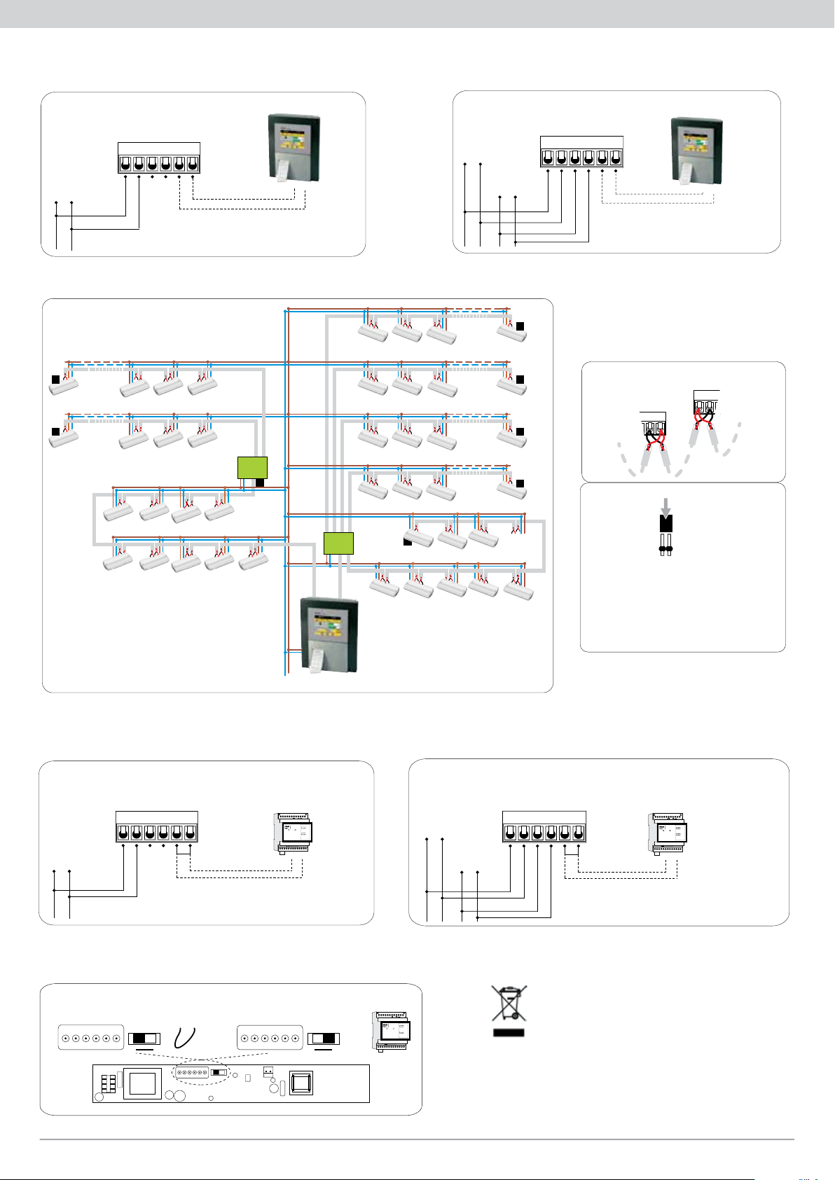
COLLEGAMENTI PER LAMPADE E-WAY TEST
Fig. 3
Fig. 1 Fig. 2
COLLEGAMENTI PER LAMPADE AUTO TEST (Test di autodiagnosi)
Fig. 4 Fig. 5
Fig. 6
SE SA
230V~
50Hz
A
B
543216
SE
B
A
- NON PERMANENTE (SE)
COLLEGAMENTI ELETTRICI
Collegare sempre la rete SE
Non collegare il ponticello A-B se si utilizza il 02795
230V~
50Hz
A
B
543216
B
A
- PERMANENTE (SA)
SE
COLLEGAMENTI ELETTRICI
SE SA
Collegare sempre la rete SE
Non collegare il ponticello A-B se si utilizza il 02795
230V~
50Hz
SA
Massimo 128 Plafoniere su questa linea Bus. Lunghezza massima del Cavo 500m
Massimo 128 Plafoniere su questa linea Bus. Lunghezza massima del Cavo 500m
Massimo 128 Plafoniere su questa linea Bus. Lunghezza massima del Cavo 500m
Massimo 128 Plafoniere su questa linea Bus. Lunghezza massima del Cavo 500m
Massimo 128 Plafoniere su questa linea Bus. Lunghezza massima del Cavo 500m
Massimo 128 Plafoniere su questa linea Bus. Lunghezza massima del Cavo 500m
Bus Termination
Bus Termination
Rete di Alimentazione 230V~
L
N
Massimo 128 Plafoniere su questa linea Bus.
Lunghezza massima del Cavo 500mt.
Plafoniere Palazzina Uffici
Plafoniere Palazzina Officine
Plafoniere Locali Tecnici
Plafoniere Locali Tecnici 2
Terminare il Bus
sul Ripetitore
T
T
T
Collegamento alla centrale con ripetitori 02829 e 02828
Linea Bus 2
Plafoniere al Piano Terra
Plafoniere al Piano Seminterrato
Plafoniere al Primo Piano
Plafoniere al Secondo Piano
Plafoniere al Terzo Piano
Plafoniere al Quarto Piano
Terminare il Bus
su quest’ultima
Plafoniera.
Terminare il Bus
su quest’ultima
Plafoniera.
Terminare il Bus
su quest’ultima
Plafoniera.
Terminare il Bus
su quest’ultima
Plafoniera.
Terminare il Bus
su quest’ultima
Plafoniera.
T
T
T
T
T
Linea Bus 1
BUS 4
BUS 3
BUS 2
BUS 1
IN OUT
BUS MASTER
02828
IN OUT
BUS MASTER
BUS 2
BUS 1
T
02829
T
Terminazione del Bus
Il Bus utilizzato deve essere un cavo bipolare (minimo
2x0,50mm²) twistato e schermato. La tipologia di
connessione deve essere Punto - Punto, ossia si deve
entrare ed uscire da ogni plafoniera come è visibile negli
schemi a lato. Il collegamento deve essere fatto rispettando
le polarità di “A” e “B” sia sulle lampade che sulla centrale.
B
B
A
A
Rispettare la polarità del Bus.
J8
Avvertenze:
Per un corretto funzionamento di tutto l’impianto occorre
Terminare il Bus inserendo i ponticelli forniti con la
centrale o con il ripetitore, sugli strip all’interno della
scheda elettronica, di tutte le lampade che si trovano alla
fine delle linee di ogni serie.
Nel caso in cui l’ultimo apparecchio sia un ripetitore
occorre terminarlo come se fosse una plafoniera, lo strip
si trova tra le morsettiere di Bus IN e Bus OUT.
SE SA
230V~
50Hz
A
B
543216
SE
B
A
230V~
02795
MODO DI RIPOSO
(OPZIONALE)
- NON PERMANENTE (SE)
COLLEGAMENTI ELETTRICI
Non collegare il ponticello A-B se si utilizza il 02795
RESTCONTROL
02795
POWEREMERGENCY
STATE
ON
OFF
EMERGENCY
MODE
AB
Collegare sempre la rete SE
SE SA
230V~
50Hz
A
B
543216
MODO DI RIPOSO
(OPZIONALE)
- PERMANENTE (SA)
230V~
50Hz
SE
SA
COLLEGAMENTI ELETTRICI
Collegare sempre la rete SE
Non collegare il ponticello A-B se si utilizza il 02795
B
A
230V~
02795
RESTCONTROL
02795
POWEREMERGENCY
STATE
ON
OFF
EMERGENCY
MODE
AB
SE SA BA
INIBIZIONE
SE SA BA
MODO DI RIPOSO
INIBIZIONE/MODO DI RIPOSO
BA
B
A
ponticello
02795
RESTCONTROL
02795
POWEREMERGENCY
STATE
ON
OFF
EMERGENCY
MODE
AB
INFORMAZIONE AGLI UTENTI AI SENSI DELLA DIRETTIVA 2002/96 (RAEE)
Al fine di evitare danni all’ambiente e alla salute umana oltre che di incorrere in
sanzioni amministrative, l’apparecchiatura che riporta questo simbolo dovrà essere
smaltita separatamente dai rifiuti urbani ovvero riconsegnata al distributore all’atto
dell’acquisto di una nuova. La raccolta dell’apparecchiatura contrassegnata con il
simbolo sopra riportato dovrà avvenire in conformità alle istruzioni emanate dagli
enti territorialmente preposti allo smaltimento dei rifiuti. Per maggiori informazioni
contattare il numero verde 800-862307.
Viale Vicenza, 14 - I 36063 Marostica VI
Tel. +39 0424 488 600 - Fax (Export) +39 0424 488 709
www.vimar.eu
Instruction sheet
E-way
02703-02704-02705-02706-02709-02710-02713-02714-02719-02720
02723-02724-02725-02726-02729-02730-02733-02734-02739-02740
GENERAL CHARACTERISTICS.
• Power supply: 230 V~, 50 Hz .
• Indicator green Led for the presence of the power supply and for the charge of the
battery.
• Indicator red led for the inhibition mode.
• Operation with rechargeable Ni-Cd and NiMH batteries.
• Constant current electronic device for the charge of the battery.
• Electrical protection device for the excessive discharge of battery.
• Possibility to be put in the stand-by mode by remote control 02795 (optional)
• Plastic body in accordance with the rules in force.
• Protection degree: IP40.
• Insulating class: II .
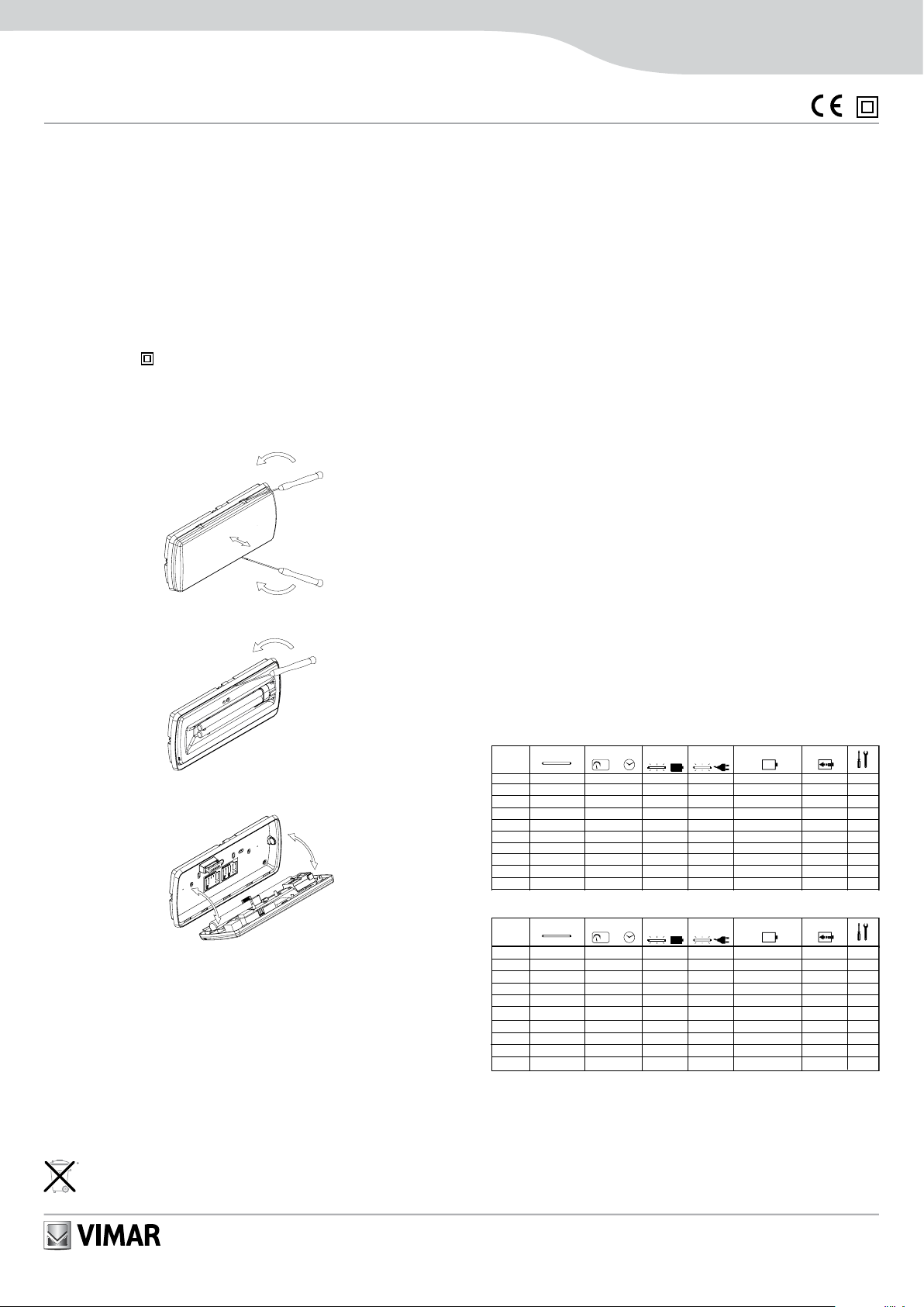
INSTALLATION.
The following procedure must be performed by qualified personnel only.
1) Remove the transparent cover pushing with a screwdriver;
2) Unhook the body of the lamp from the base with a screwdriver;
3) Drill if necessary one of the three possible entries for the power supply cable and
fix the base to the wall using the holes on the base;
4) Make the connections illustrated in figures 1 or 2 or 4 or 5.
5) Hook the body to the base making release the tooth;
6) Hook the transparent cover to the base making release the tooth.
Important: In the case of flush mounting the product must be installed with the
LED facing uppermost.
BATTERIES:
It is recommended to substitute each battery every four years or when the nominal
autonomy is not guaranteed. The model and the date of production of the battery are
written on it. Fill the field with the date of the first starting.
Warning: The Ni-Cd and Ni-MH batteries are sold uncharged: the first charge
must be 48h long.
WARNING:
Dispose of batteries in the specific differentiated collection bins.
OPERATION.
• The lamp provides auxiliary lighting in the event of a mains power failure.
• When the mains power returns the lamp will automatically switch off and the green
LED will switch on.
• Battery charging takes place continuously when there is mains voltage.
TEST FUNCTIONS.
• The lamp makes three kinds of deliberate time tests: the battery test, the functional
test and the duration test. The functional test and the duration test can be made also
in the manual way with the use of the 02795 in the normal charge mode.
• All the manual tests can be made only if there is the good ambient condition of
external light. If theexternal conditions aren’t good the test is postponed to the first
coming of the good conditions. In the time of waiting the green led flashes to indicate
that the lamp is waiting for the test.
The battery test: is done every 24 hours, it is an internal test on the conditions
of the battery.
The functional test: is done every 15 days and consists in the lighting of the fluorescent
lamp for a duration of 5 seconds. To start the manual functional test push one time the
02795 ON (make a short push no more than 2 seconds)
The duration test: is done every 90 days and consists in the complete discharge
of the battery. To start the duration test push one time the 02795 ON (make a long
push no less than 5 seconds).
Disabilitation of the tests: all deliberate time tests can be disabled with a pushing
of the button of 02795 OFF, with a second pushing of the 02795 ON deliberate time
tests will be enabled.
LED SIGNALLING.
Green Led On = Mains supply on, no warning
Green Led Fast Flashing = Battery in fast charge
Green Led Slow Flashing = Test in progress
Red Led Slow Flashing = Test disabled and inhibit luminaire
Red Led Fast Flashing = Battery fault
Red Led On = Warning luminaire
USE.
• Permanent (SA): the lamp is always on (typical used for indicator lighting).
• Non-Permanent (SE): the lamp only switches on when there is a mains power
cut (typical used for emergency lighting).
LAMPS WITH AUTO-TEST FUNCTION:
LAMPS WITH E-WAY TEST FUNCTION:
INSTALLATION RULES.
Installation should be carried out observing current installation regulations for
electrical systems in the country where the products are installed.
CONFORMITY TO STANDARDS.
LV directive. Standards EN 60598-1, EN 60598-2-22, EN 60598-2-2.
EMC directive. Standards EN 61547, EN 61000-3-2, EN 61000-3-3, EN 55015.
1.
1.
2.
3.
3.
Surface mounting emergency lighting device, supply voltage 230
V~ 50 Hz, rechargeable battery. Provided with lamp.
ART. LAMPADA
AUT.
TIPO BATTERIA
NiCd 6V 0,8Ah
NiCd 6V 2,5Ah
NiCd 6V 1,3Ah
NiMH 6V 3,3Ah
1h
3h
1h
3h
02703
02704
02705
02706
02713
02714
02709
02710
02719
02720
11W - 2G7
11W - 2G7
FLUSSO (lm) FLUSSO (lm)
139
135
195
215
–
–
NiCd 6V 1,3Ah
NiMH 6V 3,3Ah
–
–
8W - G5
8W - G5
8W - G5
8W - G5 1h
3h
142
143
288
290
NiCd 6V 1,8Ah
NiCd 6V 1,8Ah
NiMH 6V 4,0Ah
NiMH 6V 4,0Ah
NiCd 6V 1,8Ah
NiCd 6V 1,8Ah
NiMH 6V 4,0Ah
NiMH 6V 4,0Ah
312
312
294
294
284
284
308
308
445
445
445
445
24W - 2G11
24W - 2G11
24W - 2G11
24W - 2G11
24W - 2G11
24W - 2G11
24W - 2G11
24W - 2G11
1h
1h
3h
3h
1h
1h
3h
3h
RICARICA
12h
12h
12h
24h
12h
24h
12h
12h
24h
24h
12h
12h
24h
24h
POT.
3
3
3
3
11
11
W
3
3
3
3
15
15
15
15
Fig. 4
Fig. 4
Fig. 4
Fig. 4
Fig. 5
Fig. 5
Fig. 4
Fig. 4
Fig. 5
Fig. 5
NiCd 6V 0,8Ah
NiCd 6V 2,5Ah
NiCd 6V 1,3Ah
NiMH 6V 3,3Ah
1h
3h
1h
3h
11W - 2G7
11W - 2G7
139
135
195
215
–
–
NiCd 6V 1,3Ah
NiMH 6V 3,3Ah
–
–
8W - G5
8W - G5
8W - G5
8W - G5 1h
3h
142
143
288
290
12h
12h
12h
24h
12h
24h
3
3
3
3
11
11
Fig. 1
Fig. 1
Fig. 1
Fig. 1
Fig. 2
Fig. 2
Fig. 2
Fig. 2
Fig. 2
Fig. 2
02723
02724
02725
02726
02733
02734
02729
02730
02739
02740
SE SA

Fig. 3
Fig. 1 Fig. 2
Fig. 4 Fig. 5
Fig. 6
SE SA
230V~
50Hz
A
B
543216
SE
B
A
- NON MANTAINED (SE)
WIRING DIAGRAMS
Always connect the main voltage SE
Do not short the A B terminals if you are using the 02795
A
B
543216
B
A
- MANTAINED (SA)
WIRING DIAGRAMS
SE SA
Always connect the main voltage SE
Do not short the A B terminals if you are using the 02795
230V~
50Hz
SE
230V~
50Hz
SA
Max 128 luminaires on this Bus Line. 500m Max Cable Extension.
Max 128 luminaires on this Bus Line. 500m Max Cable Extension.
Max 128 luminaires on this Bus Line. 500m Max Cable Extension.
Max 128 luminaires on this Bus Line. 500m Max Cable Extension.
Bus Termination
Bus Termination
Bus Termination
on the Repeater.
Max 128 luminaires on this Bus Line. 500m Max Cable Extension.
Max 128 luminaires on this Bus Line. 500m Max Cable Extension.
Max 128 luminaires on this Bus Line.
500m Max Cable Extension.
Power supply 230V~
L
N
Luminaires Offices buildings
Luminaires workshops buildings
Luminaires Technical locals
Luminaires Technical locals 2
T
T
T
Connection to the central using 02829 and 02828 repeaters.
Line Bus 2
Line Bus 1
Downstairs
Basement
First Floor
Second Floor
Third Floor
Fourth Floor
Bus
Termination
Bus
Termination
Bus
Termination
Bus
Termination T
T
T
T
T
BUS 4
BUS 3
BUS 2
BUS 1
IN OUT
BUS MASTER
02828
IN OUT
BUS MASTER
BUS 2
BUS 1
T
02829
T
The bus used must have a bipolar, twisted and shielded
cable (min. 2x0,5 mm²). The connection is a Point to
Point type, i.e. input and output of the fixtures must be,
as shown in fig. no. 2. The connection must be done
respecting the polarity of "A" and "B" both on the lamps
and on the plant.
B
B
A
A
Respect the polarity of the Bus
J8
Attention:
For a correct operation of the whole plant it is necessary
to terminate the bus, inserting the jumpers, supplied
with the plant or with the repeater, on the strips inside
the electronic board of all the lamps that are placed at
the end of the lines of each series.
If at the end there is repeater, it is necessary to terminate
it as if it were a fixture, the strip is between the terminal
board of Bus In and Bus Out
Bus Termination
SE SA
230V~
50Hz
A
B
543216
SE
REST MODE
(OPTIONAL)
- NON MANTAINED (SE)
WIRING DIAGRAMS
Do not short the A B terminals if you are using the 02795
B
A
230V~
02795
RESTCONTROL
02795
POWEREMERGENCY
STATE
ON
OFF
EMERGENCY
MODE
AB
Always connect the main voltage SE
SE SA
230V~
50Hz
A
B
543216
REST MODE
(OPTIONAL)
- MANTAINED (SA)
230V~
50Hz
SE
SA
WIRING DIAGRAMS
Always connect the main voltage SE
Do not short the A B terminals if you are using the 02795
B
A
230V~
02795
RESTCONTROL
02795
POWEREMERGENCY
STATE
ON
OFF
EMERGENCY
MODE
AB
CONNECTION FOR E-WAY TEST LAMPS
CONNECTION FOR AUTO TEST LAMPS
SE SA BA
INHIBITION
SE SA BA
REST MODE
INHIBITION / REST MODE
BA
B
A
bridge 02795
RESTCONTROL
02795
POWEREMERGENCY
STATE
ON
OFF
EMERGENCY
MODE
AB
USER INFORMATION IN COMPLIANCE WITH DIRECTIVE 2002/96 (RAEE)
In order to prevent damage to the environment and human health as well as incur-
ring administrative sanctions, appliances bearing this symbol must be disposed of
separately from urban waste, or handed in to the distributor when buying a new
one. Appliances marked with the above symbol must be collected in conformity
with the instructions issued by the local authorities in charge of waste disposal. For
more information call the free-phone number 800-862307.
This manual suits for next models
19
Table of contents
Languages:
Other Vimar Lighting Equipment manuals


Popular Lighting Equipment manuals by other brands

superbrightleds
superbrightleds WPA-SW Series user manual

North Light
North Light WX-31VLED44-C-750WW-10-1 manual

Lightmybricks
Lightmybricks 71016 installation instructions

Sound Sation
Sound Sation LIGHTBLASTER 102 COB user manual

superbrightleds
superbrightleds WPGL Series user manual

LIVARNO LUX
LIVARNO LUX 275153 Operation and safety notes


