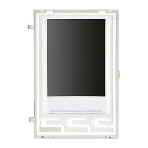
Vimar ELVOX 41018 Assembly instructions

Installer guide
41018
Display 3.5 in

16
EN
The instruction manual can be downloaded from www.vimar.com
Contents
1. BRIEF DESCRIPTION OF DEVICE ART. 41018 ...............................................................................................................15
2. FEATURES ........................................................................................................................................................................16
3. CONFIGURATION VIA PC.................................................................................................................................................17
4. CONFIGURATION VIA MENU ...........................................................................................................................................20
5. USING THE DISPLAY MODULE .......................................................................................................................................24
Installation rules
Installation should be carried out observing current installation regulations for electrical systems in the Country where the prod-
ucts are installed.
Regulatory Compliance
EMC directive
Standards EN 60065, EN 61000-6-1 and EN 61000-6-3.
INFORMATION FOR USERS UNDER DIRECTIVE 2002/96 (WEEE)
In order to avoid damage to the environment and human health as well as any administrative sanctions, any appliance marked with
this symbol must be disposed of separately from municipal waste, that is it must be reconsigned to the dealer upon purchase of a
new one. Appliances marked with the crossed out wheelie bin symbol must be collected in accordance with the instructions issued by the
local authorities responsible for waste disposal.
ENGLISH
1. BRIEF DESCRIPTION OF DEVICE
The display module provides the function of calling via the contacts list of the panel on which it is installed.
If the panel has a keypad art. 41019, calls to the indoor units can also be made by entering the desired number via
the keypad.
The device also provides visual feedback on the operating phases of the panel, such as the indications for "call in
progress" and "talking", in addition to that associated with the entry control modules.
The display module is equipped with an installation menu with which the basic panel conguration parameters can be
managed.
3.5 in display for audio or audio-video modules, 3 buttons for calls from
contacts list backlit with white LEDs, 1 input congurable as external but-
ton for CA door opener or PA door open, to be completed with front cover
This product was developed using FreeRTOSTM software - http://www.freertos.org/

17
EN
Description of wiring terminal block
Terminal function
CA- “Door open” signal sensor input: congurable function on audio/audio-video module using SaveProg (default: lock
control).
CA+
5V- External additional power supply.
Caution: You must observe the polarity in the connection.
5V+
a) Display, 3.5”
b) button (UP)
c) button (DOWN)
d) button (OK)
e) Mini USB connector for connecting to a PC.
f) Removable wiring terminal block
g) Connector for the connection to the previous electronic module
h) Connector for the connection to the next electronic module
Front and rear view
5V- 5V+CA+CA-
g
h
bcd
e
a
f
2. FEATURES
2.1. Features
• The 3.5" display has the following features: 320 x 480 pixels, 65K colours, 500 lux.
• The device must always be accompanied by an audio video module 41003, 41004 or an audio module 41001
(except for the basic audio module 41000).
• Power supply: 5V DC from audio video or audio module via harness. Maximum current draw: 220 mA. When connect-
ing the modules, observe the limit of the maximum current that can be supplied by the specic Audio/Video module
being used; if it is necessary to provide an independent power supply to the display module, the device is equipped
with an additional power supply unit on the 5V+ and 5V- terminals with a voltage of 5V DC ± 5% and a minimum
current of 220 mA.
Connecting an additional power supply unit disables the power supply input from the connected Audio/Video module,
which must in its turn be powered for the display module to work properly.
•
Operating temperature: -25 °C / +55°C.
•
Protection class: IP54
•
IK08-rated for protection against impact (Pixel)

18
EN
3. CONFIGURATION VIA PC
3.1. Programming the Contacts List and entry control codes
The contacts list (up to 8192 items) and the entry control codes (up to 2000 codes) can be programmed via the PC
programming SW (SaveProg), connecting to the audio/video module.
Follow the instructions given on SaveProg.
3.1.1. Standby views
When rst switching on, without having programmed any contacts list, the device looks like this:
Without a keypad
With a keypad installed
Press
After programming the contacts list, the standby view looks like this.
Without a keypad
With a switchboard
With switchboard and
keypad
Contacts
Press
Porter
Contacts
Extension
Contacts
Porter
3.2. Setting contacts list lters
SaveProg lets you enable a set of lters for targeted access to the subsets of the contacts list.
The available lters are described below.
3.2.1. Initials pre-lter
This lter lets you access a section of the contacts list identied by the names that start with the chosen letter.
Extension
Contacts
Porter
Users
Users

19
EN
3.2.2. Building lter
This lter lets you access the subset of users paired with a specic building.
Extension
Contacts
Porter
Buildings
Users
The Building lter can be combined with the names pre-lter.
Extension
Contacts
Porter
Buildings
Users
Users
3.2.3. Stair lter
The Stair lter lets you access the subset of users paired with a specic stair or all users.
It can be combined with the two previous lters.
In particular, with the buildings lter you obtain:
Extension
Contacts
Porter
Buildings
Stairs
Stair A
Stair B
Stair E
Stair D
Stair C
Users
Stair A
With the buildings and names lter
Extension
Contacts
Porter
Buildings
Stairs
Stair A
Stair B
Stair E
Stair D
Stair C
Users
Stair A
Users
Stair A

20
EN
3.3. Additional information
Additional information is displayed on a contacts list entry when the user hovers over it for more than 3 s.
Can be managed via SaveProg, by enabling the ag.
In order of priority:
• if present, the string of the User Information eld is displayed
• if there is no string in the Information eld, but there is one in the Secondary Name eld then the latter is dis-
played;
• if there are no strings in either User Information or Secondary Name, and there is another user with the same
ID then the name of this second user is displayed;
Extension
Contacts
Porter
Users
Back
OK
3.4. Updating
The device is updated via the USB connection.
Follow the WinBoot user instructions.
To update you need to disconnect the device from the other modules and from any auxiliary power
supply, connect the USB to the PC and start updating within 30 s.
After the 30s the device automatically exits the updating phase.
During the update the LED of the OK button will remain lit and the display will not show any images
Carry out the display update with a suitably powered PC, or with a fully-charged battery.
If, in the case of a battery-powered PC, the updating process is stopped, this will be due to an low battery level, which
is not sufcient to power the USB output used for the update. It will therefore be necessary to repeat the procedure
while the PC is powered directly from the mains electricity supply.

21
EN
4. CONFIGURATION VIA MENU
The display provides the ability to congure the basic parameters of the panel.
There are two menus:
1. administrator: the administrator side lets you modify the display module interface;
2. installer: lets you change some of the functional parameters of the panel.
You access the menu by simultaneously pressing (UP) + (DOWN) for 5 s and entering the respective pass-
words.
The passwords have a xed length and are composed of a sequence of the “ (UP)” “ (DOWN)” “ (OK)”
buttons.
The default passwords are:
Administrator: (UP) + (UP) + (UP) + (UP) + (UP)
Installer: (DOWN) + (DOWN) + (DOWN) + (DOWN) + (DOWN)
The passwords can be changed via SaveProg.
4.1. Administrator menu
The structure is summarized below:
Label Settings
Level 0 Level 1 Level 2
Display
Language
Italian, English, French, German, Spanish, Greek, Por-
tuguese, Russian, Swedish, Dutch and Polish (Default:
Italian)
Menu Navigation Navigable/Direct (Default: Navigable)
Font Normal/Large (Default: Normal)
LCD
Brightness 1-5 (Default:5)
Colours B/W, BLUE, GREEN (Default: B/W)
Standby ON/OFF (Default: ON)
The items are accompanied by the current value of the set parameter.
4.1.1. Language
This lets you choose the language of the messages of the user and installer menus.
• Language: Italian, English, French, German, Spanish, Greek, Portuguese, Russian, Swedish, Dutch and Polish
4.1.2. Menu
This lets you choose the variant of the menu structure according to need.
• Navigation: Navigable/Direct
Navigable: lets you scroll through the menu selecting the items with the arrows and entering the selected
sections with (OK);
Direct: lets you enter the items directly by pressing the (UP)/ (DOWN) control buttons of the display
module

22
EN
Select
Contacts
Porter
Contacts
Porter
Navigation Direct
• Font: Normal/Large
Changes the font size, to improve readability.
Extension
Contacts
Porter
SELEZIONA
SELECT
PORTER
EXTENSION
CONTACTS
Normal Large
4.1.3. LCD
This lets you dene the operating parameters of the display
• Brightness: 0-5
Brightness level. When there are high internal temperatures, the display is automatically dimmed.
• Colours: B/W, BLUE, GREEN
Lets you select one of the predened colour schemes for viewing the menu, according to readability.
Extension
Delete
Confirm
Extension
Delete
Confirm
Extension
Delete
Confirm
B/W BLUE GREEN
• Standby: ON, OFF
Lets you disable display standby mode, i.e. not decreasing the brightness level of the LCD when it is not being
used.
4.2. Installer menu
The structure is shown below:

23
EN
Label Settings
Level 0 Level 1 Level 2
Display
Language
Italian, English, French, German, Spanish, Greek,
Portuguese, Russian, Swedish, Dutch and Polish
(Default: Italian)
Menu Navigation Navigable/Direct (Default: Navigable)
Font Normal/Large (Default: Normal)
LCD
Brightness 1-5 (Default:5)
Colours B/W, BLUE, GREEN (Default: B/W)
Standby ON/OFF (Default: ON)
Panel
Audio Speaker 4 levels
Microphone 4 levels
Push-buttons
Setting ID - Status screen (in progress)
- Status screen (OK/fail)
Module order - Status screen (in progress)
- Status screen (OK/fail)
Grouping Single, Double, Quadruple
Addressing
Interphones - Status screen (in progress)
- Status screen (OK/fail)
Panels - Status screen (in progress)
- Status screen (OK/fail)
Timing Lock 10 values
Talk 10 values
Info
AV FW Ver xxxxx
LCD FW Ver xxxxx
KP FW Ver xxxx
System
Reset Settings OK/C (Conrm/Delete)
Reset Panel OK/C (Conrm/Delete)
Reboot Panel OK/C (Conrm/Delete)
Reboot Installation OK/C (Conrm/Delete)
External Memory
Reset OK/C (Conrm/Delete)
The Display section is described in the previous chapter "4.1 Administrator menu".
4.3. Panel
This section lets you set the basic parameters of the audio/video module of the panel. Refer to the specic instruc-
tions of the specic audio/video module for details of the settings.
4.3.1. Audio
This lets you set the operating levels of the loudspeaker and microphone.
• Speaker: 4 levels
• Microphone: 4 levels
4.3.2. Push-buttons
This lets you manage push-button conguration.
• Setting ID
Starts the "call button remapping" procedure.
• Module order

24
EN
Starts the procedure of assigning the order of the button modules.
• Grouping: Single rocker, single axial, double axial button
Lets you choose the type of grouping of the panel.
4.3.3. Addressing
This lets you start the panel and indoor unit addressing procedures.
• Interphones
Starts the indoor unit address assignment procedure.
• Panels
Starts the panel address assignment procedure.
4.3.4. Times
This lets you choose the times for:
• Lock
Lock command duration
• Talk
Maximum talk duration
4.4. Info
This section gives the release information for the devices installed on the panel.
Av fw ver = audio video module version
lcd fw ver = display module version
Kp. fw ver = keypad version
4.5. System
This section lets you restore the factory settings of the various devices or restart the panel.
• Reset Settings: Yes/No
Restores the factory default settings of the display module, after conrmation.
• Reset Panel: Yes/No
Restores the factory default settings of the panel, after conrmation.
• Reboot Panel: Yes/No
Restarts the panel.
• Reboot Installation: Yes/No
Restarts the entire Due Fili installation.
After the reboot, the display shows the screen described in paragraph 5.6.
• External Memory Reset
Conrming the External Memory Reset deletes any names in the contacts list, entry codes and button remap-
ping.

25
EN
5. USING THE DISPLAY MODULE
In standby mode the device gives the instructions to follow to access the available features depending on the type of
installation.
Depending on the programming of the contacts list and the presence of an alphanumeric keyboard, the main screen
of the display module will show the switchboard, contacts list and entry code items.
5.1. Calling from the contacts list to an extension
Go to the contacts list menu:
with switchboard without
switchboard
Select
Contacts
Porter
Contacts
Press
Scroll through the sequence of pre-lters and select the contacts list entry you want to call
Back
Pressing (OK) cancels the current call.
5.1.1. Searching for a name in the contacts list
You can search for a specic name in the contacts list also by using the multi tap function of the keypad.
From the list of names in the contacts list, press the letters forming the name on the keypad.
Each button must be pressed repeatedly until the desired letter appears on the display.
The name being formed appears at the top of the display.
In this way the display is refreshed, indicating the rst name that satises the search.
Then select the desired name and press (OK).

26
EN
Clearing the name being formed, with button C, restores the initial view.
The multi-tap function is only active if the pre-lter by initial is not active.
5.2. Calling a Switchboard
To call a switchboard there is a quick item in the main menu.
In addition, any other switchboards are accessible as contacts list entries.
5.3. Calling from the keypad
When there is a keypad you can directly enter the extension number you want to call.
Enter the extension number by following the indications on the display:
• “OK” sends the call;
• “C” clears the entry.
Extension
Contacts
Porter
Extension
Delete
Confirm
If the extension keyed in does not match a valid number, a warning is issued:
Invalid

27
EN
5.4. Call information
The device returns the status information associated with the call phase:
Calling Talking Call ended No answer
DeleteBack
Delete
Back
Concluded
Porter
No Reply
If the system is busy, with another call, the wait signal is returned:
Busy
If the user is busy or has set the user absent service, these warnings are issued:
Busy
Absent
5.5. Entry control
When there is a keypad on the panel, the display shows the feedback of the operation of the entry control mode.
This mode lets you activate a previously congured command (e.g. lock, relay, etc.).
For its operation, please refer to the instructions of the keypad module, summarized here.

28
EN
5.5.1. Operation
The keypad has 2 function keys referred to here as and .
Press the button and the display to go into “Code Entry” mode.
Each time a digit button is pressed, the display will show the digit for a short time and then overwrite it with an aster-
isk.
The entered code is conrmed by following the instructions shown on the display or by pressing again.
Personal code entry sequence: + <code> + .
5.5.2. Display feedback
The device returns the status information associated with the entry control phase:
Access to the
mode for
Entry control Entering code
Waiting for
conrmation
Code
Delete
Confirm
Code
Delete
Confirm
Code
Delete
Confirm
Feedback on actuation, after entering the code:
Done Not completed
Done
Wrong code
Audio feedback of the loudspeaker: Done -> high tone, Not done -> low tone.

29
EN
5.6. Notication messages
The device displays a variety of notication messages, whose meanings are summarized in the following table.
Notication Action required
Loading... Wait for the start-up phase to complete
Communication Timeout Check the module connections and restart the electronic unit.
Registration Error Check the module connections and restart the electronic unit.
Upgrade the modules Upgrade the display module and the audio video module to the latest FW release,
which can be downloaded from the Vimar website.
Comm. Error If the problem persists, please contact customer service.
UPGRADE TO FONTS v.1 Update via SaveProg the display fonts to version 1, using SAVEPROG version
3.1.1.12“ or major.
CHECK THE CONNECTIONS Check the connection to the electronic module and restart the device.
INCORRECT INSTALLATION Incorrect installation. Check the indications in the instructions.
For example, the following screen appears in the device start-up phase and requires waiting for the start-up phase to
complete.
Starting
Loading...
Other manuals for ELVOX 41018
3
Table of contents
Other Vimar Monitor manuals
Vimar
Vimar ELVOX 41018 User manual
Vimar
Vimar ELVOX 46910.H22B User manual
Vimar
Vimar ELVOX 46910.H18 User manual
Vimar
Vimar ELVOX 46910.H10A.01 User manual
Vimar
Vimar Elvox 46910.H32 User manual
Vimar
Vimar 46910.H10A User manual
Vimar
Vimar ELVOX 46910.H22 User manual
Vimar
Vimar Elvox TVCC 46910.43K User manual
Vimar
Vimar ELVOX Due Fili Assembly instructions
Vimar
Vimar Elvox 7200 Series Assembly instructions
