Vimar ELVOX Due Fili Assembly instructions

Manuale installatore - Installer guide
Manuel installateur - Technisches Handbuch
Instrucciones instalador - Manual do instalador
Art. 7211
Videocitofono vivavoce incasso Due Fili
Due Fili ush-mount speakerph. monitor
Portier-vidéo enc. mains libres Due Fili
UP-Freisprech-Videohaustelefon DueFili
Videoportero manos libres empotrar Due Fili
Video porteiro alta-voz de embeber Due Fili
7200

2
7200
DESCRIZIONE
L’ Art. 7211 è un videocitofono viva voce della serie 7200 con schermo a
colori TFT LCD 7” (Transistor a pellicola sottile per display a matrice attiva),
formato 16:9 Wide Screen per impianti videocitofonici DUE FILI ELVOX.
E’ dotato di una tastiera retro illuminata composta da 8 pulsanti, 4 per le
funzioni tradizionali: apertura della serratura, autoaccensione del videoci-
tofono, conversazione, servizio luce scale, e di 4 pulsanti per l’attivazione
di funzioni ausiliarie supplementari o chiamate intercomunicanti che, in
seconda funzione, si utilizzano anche per le seguenti regolazioni: regola-
zione della luminosità e del contrasto, regolazione ed esclusione del volume
suoneria, selezione del tipo suoneria, regolazione del volume di conversa-
zione, scelta della modalità di comunicazione e attivazione della funzione
di risposta automatica.
Sono inoltre presenti due LED (rosso e verde) per le segnalazioni di esclu-
sione della suoneria, porta/cancello aperto e modalità di regolazione.
Il videocitofono è fornito di una cover estraibile sostituibile con altre colo-
razioni diverse.
L’installazione del videocitofono Art. 7211 richiede l’utilizzo della scatola da
incasso Art. 7249. La scatola è in materiale ABS, è dotata di un coperchio
che impedisce l’ingresso della malta durante le fasi di muratura e la sue
dimensioni sono 189x160x52 mm.
Attenzione: Nel caso di impianti con telecamere separate, è consigliabile
adottare telecamere con risoluzione minima 420 linee TV.
Caratteristiche tecniche videocitofono
- Videocitofono in ABS.
- Morsettiera estraibile.
- Monitor a colori TFT LCD 7”, formato 16:9 Wide Screen.
- Segnale video standard PAL.
- Temperatura di funzionamento da 0° a +40° C.
- Suoneria elettronica.
- Ingresso per chiamata fuori porta con suoneria distinta dalla chiamata da
targa.
- Uscita per suoneria supplementare Art. 860A.
- Alimentazione data dal bus.
- Ingresso per alimentazione supplementare (Art. 6923) nel caso in cui si
desideri l’accensione di più di due videocitofoni contemporaneamente.
- Possibilità di scegliere tra la modalità di comunicazione “hands free”,
ovvero a mani libere senza la necessità di tenere premuto il tasto parla/
ascolta; oppure la modalità tradizionale, ovvero tenendo premuto il pul-
sante parla/ascolta.
- Dimensioni: 193x159x18 mm + 31 mm (per incasso) Connettori A-B-C
per la stabilizzazione del segnale video
Pulsante di RESET
Morsettiera di collegamento estraibile
Fig. 1B
Morsettiera di collegamento
+12, CH) Collegamento suoneria supplementare.
1, 2) Linea BUS.
E+, E-) Alimentazione supplementare per videocitofono con
alimentatore Art. 6923.
FP, M) Collegamento per pulsante di chiamata fuoriporta.
B
A
D
L
ECFHGI
M
Fig. 1A
Morsettiera di collegamento e regolazioni sul retro del videocitofono
Trimmer
per la regolazione
del colore
Comandi e controlli frontali
A) Schermo a colori TFT LCD 7”, formato 16:9 Wide Screen.
B) Microfono.
C) Altoparlante.
D) Coppia di pulsanti “” e “ ”: per l’attivazione di funzioni
ausiliarie o chiamate intercomunicanti e per la regolazione del contrasto
(con display acceso), del volume di conversazione e del volume della
suoneria (con display spento).
E) Coppia di pulsanti “ ” e “ ”: per l’attivazione di fun-
zioni ausiliarie o chiamate intercomunicanti e per regolazione della lumi-
nosità (con display acceso), e la selezione della melodia (con display
spento).
F) Pulsante : per l’autoaccensione del videocitofono sulla teleca-
mera di un posto esterno o di una telecamera scorporata (previa pro-
grammazione sulla targa) e/o per entrare in modalità di regolazione.
G) Pulsante : per servizio ausiliario, 1° relè del 1° attuatore art.
69RH (es. luci scale).
H) Pulsante : per apertura serratura.
I) Pulsante parla/ascolta: per comunicare con il posto esterno
alla ricezione di una chiamata o dopo l’autoaccensione oppure per co-
municare con apparecchi intercomunicanti. Di default la conversazione
avviene in modalità “MANI LIBERE” (Hands free). In alternativa può
essere programmato per conversazione mantenendo premuto il pul-
sante (vedi paragrafo Funzione di scelta della modalità di comunica-
zione).
L)
Segnalazione chiamata esclusa: l’accensione della segnalazione
(LED rosso) indica che la chiamata è esclusa. Inoltre il LED rosso rimane
acceso per tutta la durata della conversazione, cioè fino a che la fonica
è attiva.
M) Segnalazione porta aperta: l’accensione della segnalazione (LED
verde) indica che almeno una porta è aperta (la funzione è opzionale in
relazione al tipo di installazione).
Il lampeggio del LED verde segnala anche la modalità di regolazione
tramite i tasti frecce “ , , e ” di luminosità,
Contrasto, Volume o Melodie.
IT

3
7200
STABILIZZAZIONE SEGNALE VIDEO
Sul retro dei videocitofoni Art. 7211 sono
presenti dei connettori (A-B-C) per la stabi-
lizzazione del segnale video. Questo pon-
ticello deve essere utilizzato negli impianti
videocitofonici dove sono presenti più ap-
parecchi (citofoni e videocitofoni) collegati
in serie (fig. 6).
In configurazione serie, spostare il pon-
ticello solo dell’ultimo apparecchio nella
posizione B e mantenere i ponticelli degli
altri citofoni o videocitofoni nella posizione
iniziale ovvero A (Fig. 6).
Per altre configurazioni di collegamento
vedere: la “TABELLA TERMINAZIONE
PER IMPIANTI DUE FILI ELVOX“ riportata
nella sezione schemi di collegamento.
B
A
A
A
Fig. 7
Fig. 6
Connettori A-B-C
per la stabilizzazione del segnale video
Fig. 2A Fig. 2B
Fig. 4 Part. A
1,45 m
Fig. 6
Fig. 5
INSTALLAZIONE ART. 7211 - Montaggio da incasso parete
Il videocitofono viene fornito con cover frontale separata, in quanto deve
essere applicata solo alla fine dell’installazione.
- Installare il videocitofono lontano da fonti luminose e di calore.
- Incassare la scatola Art. 7249 al muro ad un’altezza di circa 1,45 m dal
pavimento al bordo inferiore (Fig. 2A, 2B).
Attenzione: Durante l’installazione della scatola da incasso parete Art.
7249, è necessario inserire il coperchio copriforo fornito in dotazione per
evitare eventuali deformazioni della scatola stessa.
- Estrarre la morsettiera dal fondo del videocitofono, utilizzando un caccia-
vite adeguato, facendo attenzione a far leva sui due morsetti estremi e
non sulla scheda elettronica (Fig. 3).
- Eseguire il cablaggio secondo gli schemi di collegamento.
- Ricollegare la morsettiera cablata al videocitofono assicurandosi che sia
premuta fino in fondo.
- Fissare il videocitofono alla scatola tramite le 4 viti in dotazione (Fig. 4).
- Togliere la pellicola protettiva del display (Fig. 4 - Part. A)
- Applicare la cover frontale.
Nota: Nel caso in cui fosse necessario
togliere o sostutuire la cover fron-
tale, agire con un cacciavite adeguato come illustrato in fig. 6.
Fig. 3
IT

4
7200
6) Dopo 2 secondi il citofono emette un tono acuto e viene messo in comu-
nicazione con la targa principale.
7) Rilasciare i punti e .
8) Nelle targhe a pulsanti premere il pulsante di chiamata corrispondente
al citofono/videocitofono di capogruppo. Nelle targhe alfanumeriche
comporre lo stesso codice di chiamata del citofono/videocitofono di
capogruppo e premere il pulsante .
9) Se nell’impianto esiste già un citofono/videocitofono con lo stesso co-
dice identificativo associato, la targa emette un segnale sonoro basso
ed è necessario ripetere l’operazione dall’inizio.
10) Associato l’identificativo secondario al videocitofono, la comunicazione
viene terminata.
Per conoscere il numero assegnato fare riferimento alla tabella riportata
nella sezione schemi di collegamento del manuale due fili per la targa o
unita elettronica.
Programmazione pulsanti
Il videocitofono viene fornito con tre pulsanti per le funzioni di serratura,
autoaccensione e per il servizio ausiliario “luce scale”, il quale attiva il 1°
relè del 1° attuatore (art. 69RH), se collegato all’impianto e di altri quattro
pulsanti per chiamate intercomunicanti o servizi ausiliari. Per cambiare il
tipo di funzionamento dei pulsanti è necessario utilizzare il programmatore
art. 950C o il Software per PC SaveProg, ad eccezione per l’assegnazione
delle funzioni chiamate intercomunicanti ed autoaccensione verso una targa
specifica.
Programmazione pulsanti per chiamate intercomunicanti
(Nel citofono/videocitofono dove si deve indirizzare la chiamata inter-
comunicante è necessario: per le serie 8870, Petrarca, Giotto sgan-
ciare il microtelefono, per le serie 6600 e 7200 tenere premuto il
pulsante ).
Fase di programmazione:
1) Premere e tenere premuto .
2) Successivamente premere e tenere premuto anche insieme
ad .
3) Attendere 3 secondi circa fintanto che il LED rosso inizia a lam-
peggiare.
4) Rilasciare i pulsanti e .
5) Premere e tenere premuto il pulsante da programmare (oppure
uno dei pulsanti: , , , ).
6) Dopo 2 secondi il citofono emette un tono acuto mentre l’altro citofono/
videocitofono emette una scala tritonale ascendente.
7) Rilasciare il pulsante relativo alla chiamata intercomunicante
(oppure uno dei pulsanti: , , , ).
8) Premere nel citofono/videocitofono chiamato (quello con il suono trito-
nale), il pulsante serratura.
9) Un tono acuto conferma la fine della procedura. Ripetere la stessa pro-
cedura anche per gli altri citofoni/videocitofoni ed eventuali pulsanti di
chiamata intercomunicante.
Programmazione pulsante autoaccensione verso targa specifica.
Fase di programmazione:
1) Premere e mantenere premuto .
2) Successivamente premere e tenere premuto anche “ ” insieme ad
.
3) Attendere 3 secondi circa fintanto che il LED rosso inizia a lampeg-
giare.
4) Rilasciare i pulsanti e .
5) Premere e tenere premuto il pulsante da programmare (oppure
uno dei pulsanti: , , , ).
6) Dopo 2 secondi il videocitofono emette un tono acuto.
7) Rilasciare il pulsante relativo all’autoaccensione (oppure uno dei
pulsanti: , , , ).
8) Nelle targhe a pulsanti premere il pulsante di chiamata corrispondente
al videocitofono. Nelle targhe alfanumeriche comporre il codice di chia-
mata e premere il pulsante .
9) Un tono acuto conferma la fine della procedura.
PROGRAMMAZIONE
Le programmazioni del videocitofono sono di tre tipi:
- Assegnazione codice identificativo o codice di chiamata (indispensabile);
- Assegnazione codice identificativo secondario (per videocitofoni associati
ad un citofono/videocitofono di “capogruppo”);
- Programmazione pulsanti per servizi ausiliari e chiamate intercomuni-
canti (dove necessario).
Le programmazioni devono essere effettuate con l’impianto acceso, senza
comunicazioni attive e solamente dopo aver collegato i citofoni/videocitofoni
all’impianto e programmato le targhe.
Programmazione codice identificativo
Il codice identificativo va programmato per mezzo di una targa (principale
”MASTER”), presente nell’impianto e già configurata. Il videocitofono viene
fornito senza codice identificativo associato. Per verificare ciò premere il
pulsante e il videocitofono emetterà un triplo “Bip”.
Attenzione: durante la programmazione del codice di identificazione
del videocitofono si hanno a disposizione 30 secondi dal momento in
cui si entra in programmazione nel videocitofono al momento in cui si
preme il pulsante di chiamata sulla targa o si invia il codice.
Fase di programmazione
1) Premere e tenere premuto .
2) Successivamente premere e tenere premuto anche insieme ad
.
3) Attendere 3 secondi circa fintanto che il LED rosso inizia a lampeg-
giare.
4) Rilasciare entrambi i pulsanti e . A questo punto si
hanno 5 secondi circa per eseguire una qualsiasi delle programmazioni
descritte.
5) Premere e mantenere premuto il pulsante .
6) Dopo circa 2 secondi il videocitofono emette un suono acuto, si autoac-
cende e si mette in conversazione con la targa principale.
7) Nelle targhe a pulsanti premere il pulsante di chiamata corrispondente
al videocitofono. Nelle targhe alfanumeriche comporre il codice di chia-
mata e premere il pulsante .
8) Se nell’impianto esiste già un citofono/videocitofono con lo stesso co-
dice identificativo associato, la targa emette un segnale sonoro basso
ed è necessario ripetere l’operazione dall’inizio per assegnare un codice
diverso.
9) In caso contrario il codice viene associato al videocitofono e la comuni-
cazione viene terminata.
Programmazione codice identificativo secondario
La programmazione del codice identificativo secondario è richiesta sola-
mente quando si vuole far suonare contemporaneamente più di un cito-
fono/videocitofono con lo stesso pulsante o codice di chiamata. I citofoni/
videocitofoni che devono suonare contemporaneamente vengono associati
con lo stesso pulsante ad uno stesso gruppo. Il citofono/videocitofono di
“capogruppo” viene programmato per primo attraverso la precedente pro-
cedura “programmazione codice identificativo”. I citofoni/videocitofoni ag-
giuntivi vengono programmati con il codice identificativo secondario (vedi
tabella riportata nella sezione schemi di collegamento allegati alle targhe
elettroniche DUE FILI ELVOX).
Il numero di citofoni/videocitofoni che si possono associare ad uno stesso
gruppo, senza l’ausilio del programmatore Art. 950C o SaveProg, sono tre
e un capogruppo.
Fase di programmazione:
1) Premere e tenere premuto il tasto .
2) Successivamente premere e tenere premuto anche insieme ad
.
3) Attendere 3 secondi circa fintanto che il LED rosso inizia a lampeg-
giare.
4) Rilasciare i pulsanti e .
5)
Premere contemporaneamente e mantenere premuti i pulsanti e
.
IT

5
7200
Riprogrammazione valore di default dei pulsanti.
Fase di programmazione:
1) Premere e mantenere premuto .
2) Successivamente premere e tenere premuto anche insieme ad
.
3) Attendere 3 secondi circa fintanto che il LED rosso inizia a lampeg-
giare.
4) Rilasciare i pulsanti e .
5) Premere e tenere premuto il pulsante da riportare a default.
6) Dopo 2 secondi il videocitofono emette un tono acuto.
7) Rilasciare e ripremere nuovamente il pulsante da riportare a default.
Cancellazione totale delle programmazioni.
Questa procedura è consigliata quando si vuole cambiare l’ID di un vi-
deocitofono precedentemente programmato e non si vuole mantenere
la programmazione di funzionamento dell’apparecchio.
Fase di programmazione:
1) Premere e mantenere premuto .
2) Successivamente premere e tenere premuto anche insieme
ad .
3) Attendere 3 secondi circa fintanto che il LED rosso inizia a lampeg-
giare.
4) Rilasciare i pulsanti e .
5) Premere e tenere premuto il pulsante .
6) Dopo 2 secondi il videocitofono emette, per 2 secondi, un tono lungo.
7) Rilasciare il pulsante .
8) Durante il tono lungo premere il pulsante “ ”. Se la procedura di
cancellazione è andata a buon fine, premendo il pulsante il vi-
deocitofono emetterà un triplo “Bip”.
FUNZIONAMENTO
Le chiamate da targa esterna, intercomunicanti e fuoriporta sono differen-
ziate tra loro da toni diversi.
Chiamata da targa
Le chiamate da targa non seguono la pressione del pulsante di chiamata
ma vengono generate internamente dal videocitofono. Il periodo di chia-
mata o ciclo di chiamata è 1 secondo di suono e 2 secondi di pausa ripetuto
per 2 volte (valore di default impostato nella targa). La durata delle suonerie
di tipo “Din-Don” e “Din-Don-Dan” non segue il tempo imposto dal ciclo di
chiamata ma segue il tempo naturale della suoneria.
- Fuzionamento per videocitofono programmato in modalità di comu-
nicazione “MANI LIBERE” (hands free)
Per rispondere, premere e rilasciare il pulsante . Se il pulsante
è già premuto durante la chiamata rilasciarlo e ripremerlo. Il
tempo di risposta alla chiamata (30 s) e il tempo di conversazione (2
minuti di default) sono impostati nei parametri della targa.
Per terminare la conversazione premere il pulsante .
Durante il tempo nel quale la fonica è attiva, il LED rosso rimane
acceso.
- Fuzionamento per videocitofono programmato in modalita con pul-
sante parla/ascolta PREMUTO
Per rispondere, premere e tenere premuto il pulsante . Se il pul-
sante è già premuto durante la chiamata rilasciarlo e ripremerlo.
Il tempo di risposta alla chiamata (30 s) e il tempo di conversazione (2
minuti di default) sono impostati nei parametri della targa. Scaduto il
tempo di conversazione, si può continuare, senza rilasciare il pulsante
, se viene eseguita di nuovo la chiamata entro 10 s dalla stessa
targa.
Durante la conversazione si può interrompere momentaneamente la fo-
nica (5 s massimo), rilasciando il pulsante . Per riprendere la con-
versazione ripremere il pulsante entro 5 s, altrimenti la
comunicazione decade.
Per terminare la conversazione rilasciare il pulsante .
Durante il tempo nel quale la fonica è attiva, rimane acceso il LED rosso
.
Chiamata intercomunicante
Premere il pulsante intercomunicante, se programmato, relativo al citofono/
videocitofono da chiamare. Dall’altoparlante del videocitofono chiamante si
udrà un tono di chiamata (se la chiamata è possibile) o tono di occupato (se
la chiamata non è possibile). Nel citofono/videocitofono chiamato la suone-
ria inizierà a suonare ciclicamente con un ritmo di 1 s di suono e 4 s di
pausa. La durata massima della chiamata sarà di 30 s (6 cicli). Se si desi-
dera interrompere la chiamata, premere il pulsante prima che il chia-
mato risponda. Per rispondere alla chiamata, dal videocitofono chiamato
sollevare il microtelefono o premere il pulsante (tenendolo premuto
se il videocitofono è programmato in modalità tasto parla/ascolta premuto).
Alla risposta il videocitofono sarà messo direttamente in comunicazione con
il chiamato per 5 s. La connessione della fonica avviene automaticamente.
La durata massima della conversazione è di 5 minuti. Scaduto il tempo
di conversazione si può continuare la conversazione, se viene eseguita di
nuovo la chiamata entro 10 s. Un’eventuale chiamata da targa ha priorità
su quella intercomunicante.
Chiamate rifiutate
L’esclusione della suoneria è indicata dall’accensione permanente del LED
rosso . Se vengono eseguite delle chiamate da targa verso il videoci-
tofono quando è in condizione di chiamata esclusa, queste vengono rifiu-
tate. Il rifiuto delle chiamate determina un breve spegnimento del LED rosso
tante volte quante sono le chiamate rifiutate (fino ad un massimo di 4
chiamate). La segnalazione viene ripetuta ogni 10 s circa. La cancellazione
delle chiamate rifiutate avviene con: la riabilitazione della suoneria, con il
RESET del videocitofono o l’assenza di alimentazione nell’impianto. Nelle
targa il rifiuto è segnalato con il tono dissuasione (una serie di “Bip” di
100ms con pausa di 100ms per 5 s totali). Nella targa con display viene
anche visualizzato il messaggio “Non disturbare”.
Tasto Serratura
Il tasto serratura di ogni apparecchio funziona nel modo seguente.
- Apparecchio con microtelefono a riposo serratura verso l’ultima
targa con la quale ha parlato o dalla quale è stato chiamato.
- Apparecchio con microtelefono sollevato ma non impegnato in conver-
sazione chiamata a centralino se il flag Centralino è SI. Altrimenti
si riconduce al primo caso.
- Apparecchio con microtelefono sollevato e impegnato in conversazione
interna come il primo caso
- Apparecchio con microtelefono sollevato e impegnato in conversazione
esterna o chiamato da targa apre la serratura verso la targa con
la quale sta parlando o dalla quale è stato chiamato.
N.B.: nella famiglia 7200 e 6600 la manovra equivalente è premere per un
attimo il pulsante e poi . Anche in questo caso viene chia-
mato il centralino.
IT

6
7200
Funzione di risposta automatica
La funzione, disponibile solo in modalità MANI LIBERE (hands free), consi-
ste nell’attivare la fonica del videocitofono automaticamente al ricevimento
della chiamata da posto esterno o da apparecchio intercomunicante, senza
la necessità di premere il pulsante PARLA/ASCOLTA . La condi-
zione di “fonica attiva” viene segnalata dall’accensione del LED rosso
in basso a sinistra del videocitofono, normalmente utilizzato per segnalare
l’ESCLUSIONE DELLA SUONERIA.
La fonica si attiva automaticamente dopo circa 5 secondi dal ricevimento
della chiamata.
Per abilitare questa funzione, a partire dalla situazione di videocitofono
spento, occorre premere per 2 secondi il pulsante per entrare nella
modalità di REGOLAZIONE; tenere contemporaneamente premuti i pul-
santi e fino a che il LED rosso sottostante non inizia a
lampeggiare. A questo punto, durante il lampeggio, premere il pulsante
PARLA/ASCOLTA per confermare la modifica. La funzione è stata
acquisita se il LED rosso si spegne.
Per disabilitare questa funzione, si utilizza la stessa procedura.
Nel caso in cui la modalità MANI LIBERE (hands free) non fosse stata attiva
all’atto dell’abilitazione, questa verrà automaticamente attivata all’abilita-
zione della funzione di RISPOSTA AUTOMATICA. Se successivamente
viene disabilitata la funzione di ingresso in fonica automatico, la funzione
MANI LIBERE rimane attiva.
Regolazione del volume di conversazione
Per “volume di conversazione” si intende il volume con cui percepiamo la
voce dell’interlocutore che si trova di fronte al posto esterno (targa), oppure
che parla attraverso un citofono o videocitofono intercomunicante.
Per regolare il volume di conversazione è necessario essere in comunica-
zione con un posto esterno oppure un apparecchio intercomunicante. Pre-
mere per 2 secondi il pulsante per entrare nella modalità di
REGOLAZIONE; una volta che il LED verde lampeggia, tenere pre-
muto il pulsante PARLA/ASCOLTA e regolare il volume con i pul-
santi e .
Questa procedura è valida sia in modalità MANI LIBERE (hands free) che
nella modalità con pulsante PARLA/ASCOLTA premuto.
Pulsanti , , e
Questi quattro pulsanti possono essere programmati per eseguire, quando
il videocitofono non è in modalità di regolazione, fino ad un massimo di 4
funzioni tra chiamate intercomunicanti e comandi ausiliari.
Di default il pulsante è associato al comando AUX 2, il pulsante
è associato al comando F1, il ad F2. Il pulsante non
è associato ad alcun comando, per la programmazione del pulsante
o per cambiare la funzione dei pulsanti , , o
e necessario utilizzare il programmatore Art. 950C oppure il Software per
PC SaveProg, ad eccezione per l’assegnazione delle funzioni chiamate in-
tercomunicanti ed autoaccensione verso una targa specifica, come descritto
in seguito nel paragrafo “Programmazione pulsanti”.
REGOLAZIONI
Funzioni regolazione volume suoneria e scelta melodia
Queste regolazioni avvengono in condizioni di display spento.
Premere il pulsante (autoaccensione) per 2 secondi, fino al lam-
peggio del LED verde in basso a destra , normalmente utilizzato per la
segnalazione di PORTA APERTA. Questo lampeggio segnala lo stato di
“REGOLAZIONE” durante il quale è possibile utilizzare i pulsanti e
per regolare il volume suoneria ed i pulsanti e per
scegliere la melodia.
Il videocitofono rimarrà nello stato di “REGOLAZIONE” (LED verde lampeg-
giante) fino a che i pulsanti frecce verranno premuti.
Lo stato di REGOLAZIONE termina quando i pulsanti frecce non vengono
premuti per più di 5 secondi consecutivi. È comunque possibile uscire da
questo stato premendo nuovamente il tasto fino allo spegnimento
del LED verde.
Funzione esclusione della suoneria
L’esclusione della suoneria si ottiene con la stessa procedura espressa
sopra per regolare il volume della suoneria. Una volta raggiunto il “fondo
scala” avendo ripetutamente premuto il tasto freccia giù, si accende il LED
rosso in basso a sinistra, per segnalare lo stato di “suoneria esclusa”.
Funzioni regolazione luminosità e contrasto
Queste regolazioni avvengono in condizioni di display acceso.
Premere il pulsante (autoaccensione) per 2 secondi, fino al lam-
peggio del LED verde in basso a destra, normalmente utilizzato per la
segnalazione di PORTA APERTA. Questo lampeggio segnala lo stato di
“REGOLAZIONE” durante il quale è possibile utilizzare i pulsanti e
per regolare il contrasto ed i pulsanti e per scegliere
la luminosità. I valori di fondo scala (massimo e minimo) sono segnalati da
un beep.
Il videocitofono rimarrà nello stato di “REGOLAZIONE” (LED verde lampeg-
giante) fino a che i pulsanti frecce verranno premuti.
Lo stato di REGOLAZIONE termina quando i pulsanti frecce non vengono
premuti per più di 5 secondi consecutivi. È comunque possibile uscire da
questo stato premendo nuovamente il tasto fino allo spegnimento
del LED verde.
Funzione di scelta della modalità di comunicazione (pulsante )
È possibile scegliere tra due diverse modalità di comunicazione con i posti
esterni o con apparecchi intercomunicanti:
1. Modalità MANI LIBERE (hands free): premo il pulsante PARLA/
ASCOLTA solo all’inizio della conversazione per “attivare la fo-
nica”, ed alla fine della conversazione per “disattivare la fonica”. La con-
dizione di “fonica attiva” viene segnalata dall’accensione del LED rosso
in basso a sinistra del videocitofono, normalmente utilizzato per
segnalare l’ESCLUSIONE DELLA SUONERIA.
2. Modalità con pulsante parla/ascolta PREMUTO: tengo premuto il pul-
sante parla ascolta durante la conversazione; lo rilascio alla fine
della conversazione.
Il videocitofono serie 7200 è programmato in fabbrica con la modalità di
comunicazione a MANI LIBERE (Hands free).
Per passare da una modalità all’altra, a partire dalla situazione di videocito-
fono a spento, occorre premere per 2 secondi il pulsante per en-
trare nella modalità di REGOLAZIONE; tenere contemporaneamente
premuti i pulsanti e fino a che il LED rosso sottostante
non inizia a lampeggiare. A questo punto, durante il lampeggio, premere il
pulsante PARLA/ASCOLTA per confermare la modifica. La fun-
zione è stata acquisita se il LED rosso si spegne.
IT

7
7200
Monitor technical specifications
- ABS video interphone
- Removable terminal block
- 7” TFT LCD monitor, 16:9 widescreen aspect ratio
- Standard PAL video signal
- Operating temperature from 0° to +40° C
- Electronic ringtone
- Input for landing calls with different ringtone from entrance panel calls.
- Output for additional ringtone type 860A.
- Supply of data from bus.
- Input for additional power supply (type 6923) if the user wishes simulta-
neous activation of more than two monitors.
- Option of selecting hands-free communication mode (e.g. no need to
keep the talk/listen button pressed) or push-to-talk mode
- Dimensions: 193x159x18 mm + 31 mm (for flush-mounting)
Front panel commands and controls
A) 7” TFT LCD colour screen, 16:9 aspect ratio
B) Microphone
C) Loudspeaker
D) Pair of push-buttons “ ” and “ ”: for activation of auxi-
liary functions or intercom calls and for contrast control (when display is
switched on), conversation volume and ringtone volume (when display is
switched off).
E) Pair of push-buttons “ ” and “ ”: for activation of au-
xiliary functions or intercom calls and for brightness control (when display
is switched on) and melody selection (when display is switched off).
F) Push-button : for monitor self-start on activation of the speech
unit camera or a standalone camera (programmed on the entrance
panel) and/or to enter setting mode.
G) Push-button : for auxiliary service, 1st relay of 1st actuator type
69RH (e.g. stair lights).
H) Push-button : for door lock release.
I) Talk/listen push-button: to communicate with the speech unit
on receiving a call or after self-start or to communicate with intercom
devices. The default conversation mode is “HANDS FREE”. Alternatively
the unit can be set to push-to-talk mode (see paragraph “Communication
mode selection function”).
L) Ringtone mute indicator: if the red LED lights up, this indicates
that the call tone is off. The red LED also remains on throughout the
conversation, e.g. as long as the audio connection is active.
M)
Door open indicator: if the green LED lights up, this indicates that
the door is open (this function is optional depending on the type of instal-
lation). If the green LED is flashing, this also indicates setting mode,
enabling the brightness, contract, volume or melody to be adjusted using
the arrow buttons “ , , “ and ” ”.
A-B-C connectors
for stabilisation of the video signal
RESET push-button
Removable connection terminal block
Fig. 1B
Connection terminal block
+12, CH) Additional ringtone connection.
1, 2) BUS line.
E+, E- ) Additional supply voltage for video-interphone with power
supply type 6923.
FP, M) Connection for landing call push-button.
B
A
D
L
ECFHGI
M
Fig. 1A
Connection terminal block and settings on back of monitor
Colour adjustment
trimmer
DESCRIPTION
Type 7211 is a 7200 series open-voice monitor with 7” TFT LCD screen
(thin film transistor for active matrix display) with 16:9 widescreen aspect
ratio, for ELVOX TWO-WIRE video interphone installations. It is equip-
ped with a backlit keypad consisting of 8 push-buttons, 4 for conventional
functions: door lock release, monitor self-start, conversation, stair light ser-
vice, and 4 push-buttons for activation of additional auxiliary functions or
intercom calls. These latter push-buttons are also used for the following
settings: brightness and contrast control, ringtone volume control and mute,
selection of different ringtones, conversation volume control, selection of
communication mode and activation of automatic answer function. The de-
vice also has two LEDs (red and green) for indicating ringtone mute, door/
gate open and setting mode.
The monitor is equipped with a removable cover and is available in a range
of alternative colours. Installation of monitor type 7211 requires the use of
back box type 7249.
The back box is made of ABS plastic and is equipped with a cover to pre-
vent the ingress of mortar and grout during masonry work. Its dimensions
are 189x160x52 mm.
Caution: In the case of systems with separate cameras, we recommend
using cameras with a minimum resolution of 420 TV lines.
EN

8
7200
VIDEO SIGNAL STABILISATION
On the rear of monitor type 7211 there are
some connectors (A-B-C) for the video si-
gnal stabilization.
This jumper must be used in installations
with several appliances (interphones and
monitors) connected in series (Fig. 6).
In series configuration displace the jum-
per (only in the last set) into “B” position
and keep the jumpers of other interpho-
nes or monitors in the initial position, i.e.
“A” (Fig. 6).
For other connection configurations see
the: TERMINATION TABLE FOR THE
TWO WIRE ELVOX INSTALLATIONS”
shown in the wiring diagram section.
B
A
A
A
Fig. 7
Fig. 6
Fig. 2A Fig. 2B
Fig. 4 Part. A
1,45 m
Fig. 6
Fig. 5
Fig. 3
INSTALLATION OF TYPE 7200 - Flush-mount assembly
The monitor is supplied with a separate front cover, since it must only be
fitted at the end of the installation.
- Install the monitor away from sources of light and heat
- Install the flush-mount back box type 7249 at a height of approximately
1.45 m from the floor to the lower edge (Fig. 2A, 2B)
Caution: When installing flush-mount back box type 7249, it is necessary
to insert the bezel supplied in order to prevent deformation of the box
itself
- Extract the terminal block from the bottom of the monitor, using a suitable
screwdriver, taking care to lever the two end terminals and not the circuit
board (Fig. 3)
- Make the connection following the wiring diagrams
- Reconnect the wired terminal block to the monitor, ensuring that it fits
snugly
- Fit the monitor to the box using the 4 screws supplied (Fig. 4)
- Remove the protective film from the display (Fig. 4 - Part A)
- Fit the front cover
Note: If for any reason you need to remove or replace the front cover, use
a suitable screwdriver as shown in Fig. 6.
A-B-C connectors
for stabilisation of the video signal
EN

9
7200
8) On the push-buttons entrance panels press the call push-button corre-
sponding to the main (already programmed) interphone / video-inter-
phone, on the alphanumeric entrance panel, on the contrary, enter the
same call code of the “Master” interphone / video-interphone and press
“”.
9) If on the installation there is already an interphone / video-interphone with
the same associated identification code, the panel emits a low-pitched tone
and you must repeat the operation from the beginning.
10) Once the secondary identification code is associated to the video-inter-
phone, the communication is terminated.
To find out the assigned number, refer to the table given in the wiring dia-
grams section of the Two-Wire manual entrance panel or electronic unit.
Programming the push-buttons
The video-interphone is supplied with 3 push-buttons for the following
functions: lock release, self-start and “stair light” auxiliary service, which
activates the 1st relay of the 1st actuator (type 69HR), if connected to the
installation and with other 6 push-buttons for intercommunicating calls or
auxiliary services.
To change the operation type of push-buttons it is necessary to use pro-
grammer type 950C or SaveProg, with the exception of the assignation of
the functions for the intercommunicating calls and self-start to a specific
entrance panel.
Programming the push-buttons for the intercommunicating calls
(In the audio/video door entry unit where the intercom call is to be sent
it is necessary to pick up the handset (8870, Petrarca and Giotto se-
ries) or hold down push-button (for the 6600 and 7200 series).
Programming phase:
1) Press and hold down .
2) Press and hold down also together with .
3) Wait for nearly 3 seconds until the red led flashes.
4) Release both push-buttons and .
5) Press and hold down the push-button to be programmed (or
one of push-button: , , , ).
6) After 2 seconds the video-interphone emits a high-pitched tone, while
the other interphone / video-interphone emits a three-tone ascending
scale.
7) Release the push-button related to the intercommunicating call
(or one of push-button: , , , ).
8) On the interphone/monitor called (with the 3-tone ring), press the lock
release push-button.
9) A high-pitched tone confirms the end of the procedure.
Repeat the procedure also for the other interphones / video-interphones
ad possible intercommunicating call push-buttons.
Programming the self-start push-button to a specific entrance panel.
Programming phase:
1) Press and hold down .
2) Press and hold down also
“ ”
together with “ ”.
3) Wait for nearly 3 seconds until the red led “ ” flashes.
4) Release both push-buttons and .
5) Press and hold down the “ ” push-button to be programmed (or
one of push-button: , , , ).
6) After nearly 2 seconds the video-interphone emits a high-pitched tone.
7) Release the push-button “ ” related to the self-start (or one of
push-button: , , , ).
8) On the entrance panels with push-buttons press the call push-button
corresponding to the video -interphone; on the alphanumeric entrance
panel, on the contrary, enter the call code and press “ ”.
9) A high-pitched tone will confirm the end of the procedure.
PROGRAMMING
There are three monitor programming modes: assignment of an identifica-
tion code or call code (indispensable), assignment of a secondary identifica-
tion code (for video interphones associated with a master video interphone),
programming of push-buttons for auxiliary services and intercommunicating
calls (when necessary).
Programming must be performed with the system switched on, without
active communication and only after connecting the interphones/video in-
terphones to the system and programming the panels.
Programming the identification code
The identification code is to be programmed by means of an entrance panel
(main- “Master”), present on the installation and already configurated. The
video-interphone is supplied without associated identification code. To
check this, press the push-button and the video-interphone will emit
a triple “Beep”.
Attention: during the interphone/video interphone identification code
programming you have 30 seconds from the moment you enter the
programming in the interphone/video interphone and the moment you
press the call push-button on the panel or you send the code.
Programming phase:
1) Press and hold down .
2) Press and hold down also together with .
3) Wait for nearly 3 seconds until the red led flashes.
4) Release both push-buttons and . You have now 5 se-
conds to carry out any of the described programmings.
5) Press and hold down the lock push-button.
6)
After approximately 2 seconds the video door entry unit emits a high tone,
it self-starts and communication is enabled with the main entrance panel.
7) On the entrance panels with push-buttons press the call push-button
corresponding to the video-interphone, on the alphanumeric entrance
panel, on the contrary, enter the call code and press “ ”.
8)
If the system already contains an audio/video door entry unit that has the
same associated identification code, the panel emits a low sound signal
and the operation needs to be repeated from the start in order to assign a
different code.
9) If not, the code is associated to the video-interphone and the commu-
nication is terminated.
Programming the secondary identification code
The programming of the secondary identification code is required only
when you want more than a video- interphone to ring at the same time
with the same push-button or call code. The video-interphones which must
ring simultaneously are associated with the same push-button to the same
group. The “master” interphone / video-interphone is programmed in first
place by means of the previous procedure: “programming the identification
code”. The additional interphones / video-interphones are programmed with
the secondary identification code (see table shown in the wiring diagram
section enclosed with the electronic TWO WIRE ELVOX entrance panels).
A maximum of three audio door entry units plus one group master can be
associated with the same group, without the need for programmer Type
950C or SaveProg.
Programming phase:
1) Press and hold down .
2) Press and hold down also together with
.
3) Wait for nearly 3 seconds until the red led flashes.
4) Release both push-buttons and .
5) Press both push-buttons and .
6) After 2 seconds the video-interphone emits a high-pitched tone and
gets in communication with the entrance panel.
7) Release the door lock and the self-start push-buttons.
EN

10
7200
Restoring the default values of push-buttons
Programming phase:
1) Press and hold down .
2) Press and hold down also together with .
3) Wait for nearly 3 seconds until the red led flashes.
4) Release both push-buttons and
5) Press and hold down the push-button to be restored to its default set-
ting.
6) After 2 seconds the video-interphone emits a high-pitched tone.
7) Release and press again the push-button to be restored to default.
Deleting all settings
This procedure is recommended when you want to change the ID of
a previously programmed video-interphone without retaining its pro-
gramming parameters.
Programming phase:
1) Press and hold down .
2) Then press and hold down also together with .
3) Wait for nearly 3 seconds until the red led flashes.
4) Now the microprocessor is physically reset.
5) Release both push-buttons and .
6) Press and hold down the self-start push-button .
7) After 2 seconds the video-interphone emits a continuous tone for two
seconds.
8) Release the self-start push-button .
9) During the long tone press the lock push-button .
If the deletion procedure was successful, press the lock push-button
and the video-interphone will emit a triple “BEEP”.
OPERATION
Calls from an entrance panel, intercommunicating calls and landing calls
are differentiated by means of different tones.
Call from entrance panel
Calls from entrance panels are not activated after the push-button is pres-
sed but are generated inside the monitor. The call interval or call cycle is a
1-second ringtone and a 2-second pause repeated twice (default value set
on panel). The duration of “Ding-Dong” and “Ding-Dong-Dang” ringtones
follows the natural length of the ringtone, rather than the time set by the
call cycle.
- Operation for monitor programmed in “HANDS FREE” communica-
tion mode
To answer, press and release push-button . If push-button
is already pressed during the call, release and press it again.
The call answer time (30 secs) and the conversation time (2 minutes by
default) are set in the panel parameters. To end the conversation, press
push-button . The red LED remains on as long as the audio
connection is active.
- Operation for monitor programmed in “PUSH-TO-TALK” communi-
cation mode
To answer, press and release push-button . If push-button
is already pressed during the call, release and press it again. The call
answer time (30 secs) and the conversation time (2 minutes by default)
are set in the panel parameters. When the conversation time has elap-
sed, the user can continue without pressing push-button again,
if a new call is made within 10 seconds from the same panel. During
conversation, the audio connection can be momentarily interrupted (5
seconds max), by releasing push-button . To resume the conver-
sation, press push-button again within 5 seconds, otherwise
communication is lost.
To end the conversation, release push-button . The red LED
remains on as long as the audio connection is active.
Intercom call
Press the intercom button, if programmed, for the interphone/monitor to be
called. From the loudspeaker of the monitor called, a call tone will ring (if the
call is enabled) or an engaged tone will ring (if not enabled). On the called
interphone/monitor the ringtone starts sequentially at intervals of 1 second
ringing and 4 seconds pause. The maximum duration of the call is 30 se-
conds (6 cycles). To interrupt the call, press push-button before the
call recipient answers. To answer the call from the called monitor, lift the
handset or press push-button (keeping it pressed if the monitor is
programmed to push-to-talk mode). When the call is answered, the monitor
will be put directly in communication with the call recipient for 5 seconds.
The audio connection is made automatically. The maximum duration of the
conversation is 5 minutes. When the conversation time has elapsed, the
user can continue the conversation if a new call is made within 10 seconds.
Calls from entrance panel have priority over intercommunicating calls.
Denied calls
Call mute is indicated by steady illumination of the red LED . If calls are
made from the entrance panel to the monitor when call mute is enabled, they
are denied. A denied call causes the red LED to briefly switch off ac-
cording to the number of times calls are denied (maximum 4 denied calls).
The signal is repeated every 10 seconds (approx.). Deletion of denied calls
is by: re-enabling the ringtone, pressing the RESET button on the monitor,
or a system power failure. On the panel, a denied call is indicated by means
of a dissuasion tone (a series of beeps at 100ms intervals with a pause of
100ms for a total of 5 seconds). The message “Do not disturb” also appears
on panels with display.
Lock Release Button
The lock release button of each device functions as follows.
- Device with handset on hook : opens the lock corresponding to the
last entrance panel in communication with the device (whether incoming
or outgoing call).
- Device with handset off hook but not engaged in conversation : call
to switchboard if the Switchboard flag is YES. Otherwise it reverts to the
first case.
- Device with handset off hook and engaged in internal conversation
: as per first case
- Device with handset off hook and engaged in external conversation or
call from entrance panel : opens the lock corresponding to the last
entrance panel in communication with the device (whether incoming or
outgoing call).
NOTE: in the 7200 and 6600 family the equivalent operation is performed
by briefly tapping push-button and then . Also in this case the
switchboard is called.
EN

11
7200
Automatic answer function
This function, which is only available in HANDS FREE mode, activates the
monitor audio connection automatically when a call is received from the
speech unit or intercom device, without the need to push the TALK/LISTEN
button . The “audio active” condition is indicated by the illumination
of the red LED at the bottom left corner of the monitor, which is nor-
mally used to indicate RINGTONE MUTE. The audio is activated automati-
cally 5 seconds after the call is received. To enable this function, with the
monitor switched OFF press push-button for 2 seconds to enter
SETTING mode; simultaneously press and hold down push-buttons
and until the red LED underneath starts flashing. At this point,
while the LED is flashing, press the TALK/LISTEN push-button to
confirm the change. The function is confirmed if the red LED switches off.
To disable this function, follow the same procedure. If HANDS FREE mode
was not active during the enabling process, it will be activated automatically
when the AUTOMATIC ANSWER function is enabled. If the automatic an-
swer function is subsequently disabled, the HANDS FREE function will re-
main active.
Adjusting the conversation volume
The term “conversation volume” refers to the perceived volume of the cal-
ler’s voice when he/she is standing in front of the speech unit (entrance
panel), or speaking through an intercommunicating interphone or monitor.
To adjust the conversation volume, the user must be in communication with
a speech unit or intercom device. Press push-button for 2 seconds
to enter SETTING mode; once the green LED starts flashing, press
and hold the TALK/LISTEN push-button and adjust the volume with
push-buttons and . This procedure applies both in HANDS
FREE mode and in PUSH-TO-TALK mode.
Push-buttons , , and
These four push-buttons can be programmed to perform up to 4 functions
including intercom calls and auxiliary commands, when the monitor is not in
setting mode. By default, push-button is associated with the AUX 2
command, push-button is associated with the F1 command, pu-
sh-button with F2.
Push-button is not associated with any command. To program pu-
sh-button or to change the function of push-buttons , ,
or , use programmer type 950C or the SaveProg software
for PC, except for assigning the functions of intercommunicating calls and
self-start service to a specific panel, as described below in the paragraph
“Programming push-buttons”.
SETTINGS
Ringtone volume and melody selection functions
These settings can be adjusted with the display switched off. Press pu-
sh-button (self-start) for 2 seconds, until the green LED at the
bottom right flashes. This LED is normally used to indicate DOOR OPEN.
This flashing indicates “SETTING” mode, during which buttons and
can be used to adjust the ringtone volume and push-buttons
and to select the melody.
The monitor will remain in “SETTING” mode (green LED flashing) until the
arrow buttons are pressed. SETTING mode is cancelled when the arrow
buttons are not pressed for more than 5 seconds. Nevertheless the user can
exit this mode by pressing button again until the green LED swi-
tches off.
Ringtone mute function
Ringtone mute is activated using the same procedure described above for
adjusting the ringtone volume. Once the volume has been adjusted to the
lowest setting by repeatedly pressing the down arrow, the red LED in
the bottom left-hand corner illuminates to indicate that ringtone mute is acti-
vated.
Brightness and contrast control functions
These settings can be adjusted with the display switched on. Press pu-
sh-button (self-start) for 2 seconds, until the green LED at
the bottom left flashes. This LED normally serves as the OPEN DOOR indi-
cator. This flashing indicates entry into “SETTING” mode, during which but-
tons and can be used to set the contrast and buttons
and to select the brightness. When the maximum and minimum
values are reached, this is indicated by a beep. The monitor will remain in
“SETTING” mode (green LED flashing) until the arrow buttons are pressed.
SETTING mode is cancelled when the arrow buttons are not pressed for
more than 5 seconds. Nevertheless the user can exit this mode by pressing
button again until the green LED switches off.
Communication mode selection function ( button)
It is possible to choose between two different modes of communication with
speech units or intercom devices:
1. HANDS FREE mode: press the TALK/LISTEN push-button at the
start of the conversation only, to activate the audio, and at the end of the
conversation to deactivate the audio. The “audio active” condition is indi-
cated by the illumination of the red LED at the bottom left corner of
the monitor, which is normally used to indicate RINGTONE MUTE.
2. PUSH-TO-TALK mode: keep the talk/listen push-button pressed
during the conversation; release it at the end of the conversation.
The 7200 series monitor is factory set to HANDS FREE communication
mode. To switch from one mode to the other, with the monitor switched OFF
press push-button for 2 seconds to enter SETTING mode; simul-
taneously press and hold down push-buttons and until the
red LED underneath starts flashing. At this point, while the LED is
flashing, press the TALK/LISTEN push-button . to confirm the
change. The function is confirmed if the red LED switches off.
EN

12
7200
DESCRIPTION
L’Art. 7211 est un moniteur mains libres de la série 7200 avec écran
couleurs TFT LCD 7” (Transistor à pellicule fine pour afficheur à matrice
active), format 16:9 Wide Screen pour systèmes visiophoniques DEUX
FILS ELVOX. Il est équipé d’un clavier rétro-éclairé comprenant 8 boutons,
4 pour les fonctions traditionnelles : ouverture de la gâche, auto-allumage
du moniteur, conversation, service lumières d’escalier, et 4 boutons pour
l’activation de fonctions auxiliaires supplémentaires ou appels intercom-
municants qui, selon la fonction, s’utilisent également pour les réglages
suivants : réglage de la luminosité et du contraste, réglage et exclusion du
volume de la sonnerie, sélection du type de sonnerie, réglage du volume de
conversation, choix du mode de communication et activation de la fonction
de réponse automatique. En outre, deux leds (rouge et verte) signalent
l’exclusion de la sonnerie, la porte ouverte ou le portail ouvert et le mode
de réglage.
Le moniteur possède une façade amovible qui permet de choisir parmi de
nombreuses colorations différentes. Pour installer le moniteur Art. 7211,
utiliser la boîte d’encastrement Art. 7249. La boîte est en matière plastique
ABS, équipée d’un couvercle pour éviter que le mortier n’entre dans la boîte
durant les phases de murage. Ses dimensions sont : 189x160x52 mm.
Attention : En cas d’installations avec caméras séparées, il est conseillé
d’adopter des caméras avec résolution minimum de 420 lignes TV.
Caractéristiques techniques du moniteur
- Moniteur en ABS.
- Bornier amovible.
- Moniteur couleurs TFT LCD 7”, format 16:9 Wide Screen.
- Signal vidéo standard PAL.
- Gamme de température de fonctionnement de 0° à +40°C.
- Sonnerie électronique.
- Entrée pour appel de palier avec sonnerie différente de l’appel de la
plaque de rue.
- Sortie pour sonnerie supplémentaire art. 860A.
- Alimentation fournie par bus.
- Entrée pour alimentation supplémentaire (Art. 6923) si l’on désire avoir
l’allumage de plus de deux moniteurs en même temps.
- Possibilité de choisir entre le mode de communication “hands free”
c’est-à-dire mains libres sans avoir besoin de maintenir la touche parler/
écouter appuyée ; ou bien le mode traditionnel c’est-à-dire en mainte-
nant la touche parler/écouter enfoncée.
- Dimensions : 193x159x18 mm + 31 mm (pour encastrement)
Commandes et contrôles frontaux
A) Écran TFT LCD 7” couleurs, format 16:9
B) Microphone.
C) Haut-parleur.
D) Paire de boutons “ ” et “ ” : pour l’activation de
fonctions auxiliaires ou appels intercommunicants et pour le réglage du
contraste (avec afficheur allumé), du volume de conversation et du vo-
lume de la sonnerie (avec afficheur éteint).
E) Paire de boutons “ ” et “ ” : pour l’activation de
fonctions auxiliaires ou appels intercommunicants et pour le réglage de
la luminosité (avec afficheur allumé), et la sélection de la mélodie (avec
afficheur éteint).
F) Bouton : pour l’auto-allumage du moniteur sur la caméra d’un
micro haut-parleur ou d’une caméra déportée (après programmation
sur la plaque de rue) et/ou pour entrer en mode de réglage.
G) Bouton : pour service auxiliaire, 1er relais du 1er actionneur
art. 69RH (ex. lumières d’escalier).
H) Bouton : pour ouverture de la gâche.
I) Bouton parler/écouter : pour communiquer avec le micro
haut-parleur à la réception d’un appel ou après l’auto-allumage ou pour
communiquer avec des appareils intercommunicants. Par défaut, la
conversation a lieu en mode “MAINS LIBRES” (Hands free). En alter-
native, on peut le programmer pour la conversation en maintenant le
bouton appuyé (voir paragraphe Fonction de choix du mode de com-
munication).
L) Signalisation appel exclu : l’allumage de la signalisation (led
rouge) indique que l’appel est exclu. En outre, la led rouge reste allu-
mée pendant toute la durée de la conversation c’est-à-dire tant que la
fonction phonique est active.
M) Signalisation porte ouverte : l’allumage de la signalisation (LED
verte) indique qu’au moins une porte est ouverte (cette fonction est une
option selon le type d’installation). Le clignotement de la led verte si-
gnale également le mode de réglage au moyen des touches fléchées “
, , et ” de luminosité, contraste, volume
ou mélodies.
Connecteurs A-B-C
pour la stabilisation du signal vidéo
Bouton de RESET
Bornier de connexion amovible
Fig. 1B
Bornier de connexion
+12, CH) Raccordement sonnerie supplémentaire
1, 2) Ligne BUS.
E+, E- ) Alimentation supplémentaire pour moniteur avec alimentateur
art. 6923.
FP, M) Raccordement pour bouton d’appel de palier.
B
A
D
L
ECFHGI
M
Fig. 1A
Bornier de raccordement et réglages au dos du moniteur
Variateur de rég-
lage de la couleur
FR

13
7200
STABILISATION DU SIGNAL VIDÉO
Derrière les moniteurs Art. 7211 il y a des
connecteurs (A-B-C) et des pontages pour
la stabilisation du signal vidéo.
Ce pontage doit être employé dans les in-
stallations avec plusieurs appareils (postes
d’appartement et moniteurs) et raccordés
en série (Fig. 6).
Dans la configuration en série déplacer le
pontage (seulement dans le dernier ap-
pareil) sur la position “B” et maintenir les
pontages des autres postes d’appartement
ou moniteurs sur la position initiale ou “A“
(Fig. 6).
Pour les autres configurations de raccor-
dement voir la « TABLE TERMINATION
POUR INSTALLATIONS DE DEUX FILS
ELVOX » indiquée dans la section schémas
de raccordement.
B
A
A
A
Fig. 7
Fig. 6
Connecteurs A-B-C
pour la stabilisation du signal vidéo
Fig. 2A Fig. 2B
Fig. 4 Part. A
1,45 m
Fig. 6
Fig. 5
INSTALLATION ART. 7211 - Montage à encastrer
Le moniteur est équipé d’une façade séparée qui ne doit être appliquée qu’à
la fin de l’installation.
- Installer le moniteur loin des sources lumineuses et de chaleur.
- Encastrer la boîte Art. 7249 dans le mur à une hauteur de 1,45 m environ
du sol au bord inférieur (Fig. 2A, 2B).
Attention : Durant l’installation de la boîte d’encastrement Art. 7249, in-
sérer le couvercle cache-trou fourni pour éviter les éventuelles déformat-
ions de ladite boîte.
- Extraire le bornier au fond du moniteur, en utilisant un tournevis approprié
et en faisant levier sur les deux bornes aux extrémités et non sur la carte
électronique (Fig. 3).
- Effectuer le câblage selon les schémas de raccordement.
- Reconnecter le bornier câblé au moniteur en le pressant bien jusqu’au
fond.
- Fixer le moniteur à la boîte au moyen des 4 vis fournies (Fig. 4).
- Enlever la pellicule de protection du display (Fig. 4 - Pièce A)
- Appliquer la façade.
Remarque : Pour ôter ou remplacer la façade en cas de besoin, utiliser
un tournevis approprié comme illustré sur la fig. 6.
Fig. 3
FR

14
7200
7) Rélâcher les boutons gâche et autoallumage .
8) Appuyer sur le bouton d’appel correspondant à l’interphone / portier-vi-
déo “Master” sur les plaques de rue à boutons. Taper le code d’appel
de l’interphone / vidéo-portier et appuyer sur le bouton “ ” sur les
plaques de rue alphanumériques.
9) Si dans l’installation existe déjà un interphone / portier-vidéo avec le
même code d’identification associé, la plaque émet un signal sonore
faible et il est nécessaire de répéter l’opération du point 1.
10) Une fois l’identificateur secondaire associé au portier-vidéo, la commu-
nication termine.
Pour connaître le numéro attribué, se référer au tableau présent dans la
section Schémas de raccordement du manuel deux fils pour la plaque de
rue ou l’unité électronique.
Programmation des boutons
Le portier-vidéo est fourni avec 3 boutons pour les fonctions de gâche, au-
toallumage et pour le service auxiliaire d’éclairage escalier, lequel active le
1er relais du 1er actionneur (Art. 69R4), si connecté au système et d’autres
6 boutons pour les appels intercommunicants ou services auxiliaires. Pour
changer le type de fonctionnement des boutons il est nécessaire d’utiliser
le programmateur Art. 950C ou SaveProg, excepté pour l’affectation des
fonctions des appels intercommunicants et autoallumage vers une plaque
de rue spécifique.
Programmation des boutons pour appels intercommunicants
(dans le poste/moniteur où il faut adresser l’appel intercommunicant
il est nécessaire : pour les séries 8870, Petrarca, Giotto, de décrocher
le combiné, pour les séries 6600 et 7200, de maintenir le bouton
enfoncé).
Étape de la programmation:
1) Appuyer et garder le doigt sur le bouton .
2) Appuyer et garder le doigt sur le bouton en même temps que
le bouton .
3) Attendre environ 3 secondes jusqu’à ce que la led rouge ne cli-
gnote.
4) Rélâcher les boutons et .
5) Appuyer et garder le doigt sur le bouton à programmer (ou un
bouton: , , , ).
6) Après 2 secondes, l’interphone émet une tonalité aiguë, tandis que
l’autre interphone/portier-vidéo émet une échelle tritonale ascendante.
7) Rélâcher le bouton relatif à l’appel intercommunicant (ou un
bouton: , , , ).
8) Appuyer sur le bouton gâche sur le poste d’appartement/moniteur ap-
pelé (celui avec le son à trois tonalités).
9) Une tonalité aiguë confirme la fin de la procédure.
Répéter la même procédure pour les autres interphones / portiers-vi-
déos et éventuels boutons d’appel l’intercommunicant.
Programmation du bouton d’autoallumage vers la plaque de rue spécifique.
Étape de la programmation:
1) Appuyer et garder le doigt sur le bouton .
2) Appuyer et garder le doigt sur le bouton en même temps que
sur .
3) Attendre environ 3 secondes jusqu’à ce que la led
ne clignote.
4) Rélâcher les boutons et .
5) Appuyer et garder le doigt sur le bouton à programmer (ou un
bouton: , , , ).
6) Après 2 secondes, le portier-vidéo émet une tonalité aiguë.
7) Relâcher le bouton d’autoallumage (ou un bouton: ,
, , ).
8) Appuyer sur le bouton d’appel correspondant au portier-vidéo sur les
plaques de rue à boutons. Taper lecode d’appel et appuyer sur le
bouton “ ” sur les plaques de rue alphanumériques.
9) Une tonalité aiguë confirme la fin de la procédure..
PROGRAMMATION
Les programmations du portier-vidéo sont de trois types : attribution d’un
code d’identification ou d’un code d’appel (indispensable), d’un code d’i-
dentification secondaire (pour portiers-vidéos associés à un portier-vidéo
“Master”), programmation des boutons pour services auxiliaires et commu-
nication entre postes (lorsque cela est nécessaire).
Les programmations doivent être effectuées avec le système allumé, sans
communication en cours et seulement après avoir relié les interphones et/
ou portiers- vidéos au système et programmé les plaques de rue.
Programmation code identification
Le code d’identification doit être programmé par l’intermédiaire d’une plaque
de rue (principale-”MASTER”), montée dans le système et déjà configurée.
Le portier-vidéo est fourni sans code d’identification associé. Pour vérifier
cette condition, appuyer sur le bouton de commande de la gâche .
Le portier-vidéo émettra un triple “Beep”.
Attention: pendant la programmation du code d’identification du poste
d’appartement/portier-vidéo il y a 30 seconds du moment dans lequel
on entre en programmation dans le poste d’appartement/portier-vidéo
au moment dans lequel on appuie sur le bouton-poussoir d’appel ou
on envoie le code.
Étape de la programmation:
1) Appuyer et garder le doigt sur le bouton .
2) Appuyer et garder le doigt sur les boutons en même temps que
le bouton
.
3) Attendre environ 3 secondes jusqu’à ce que la led rouge ne cli-
gnote.
4) Rélâcher les deux boutons et .
Vous avez environ 5 secondes pour programmer une de n’importe
quelle programmation décrite.
5) Appuyer et garder le doigt sur le bouton .
6) Après 2 secondes environ, le moniteur émet un son aigu, il s’auto-al-
lume et il se met en conversation avec la plaque de rue principale.
7) Appuyer sur le bouton d’appel correspondant au vidéo-interpohone sur
les plaques de rue à boutons. Taper le code d’appel et appuyer sur le
bouton “ ” sur les plaques de rue alphanumériques.
8)
Si l’installation comprend déjà un poste/moniteur avec le même code
d’identification associé, la plaque de rue émet un signal sonore faible et il
faut nécessairement reprendre l’opération depuis le début pour attribuer
un code différent.
9) Dans le cas contraire, le code est associé au portier-vidéo et la com-
munication est coupée.
Programmation du code d’identification secondaire
La programmation du code d’identification secondaire n’est requise que
pour faire sonner simultanément plus d’un portier-vidéo avec le même bou-
ton ou code d’appel. Les portiers-vidéos qui doivent sonner simultanément
sont associés avec le même bouton à un même groupe. L’interphone /
portier-vidéo “Master” est programmé le premier en utilisant la procédure
précédente de “programmation du code d’identification”. Les interphones /
portiers-vidéos supplémentaires sont programmés avec le code d’identifi-
cation secondaire (voir table indiquée dans les schémas de raccordement
avec les plaque de rue électroniques DEUX FILS ELVOX). Le nombre d’in-
terphones que l’on peut associer au même groupe, sans l’aide du program-
mateur art. 950C ou SaveProg, est 3 plus un chef de groupe.
Étape de la programmation:
1) Appuyer et garder le doigt sur le bouton .
2) Appuyer et garder le doigt simultanément sur les boutons
et
.
3) Attendre 3 secondes jusqu’à ce que la led rouge ne clignote.
4) Relâcher les boutons et .
5) Appuyer simultanément et garder le doigt sur les boutons gâche
et autoallumage
.
6) Après 2 secondes environ, le moniteur émet un son aigu, il s’auto-al-
lume et il se met en conversation avec la plaque de rue principale.
FR

15
7200
Reprogrammation de la valeur par défaut (autrement dit d’usine) des
boutons.
Étape de la programmation :
1) Appuyer et garder le doigt sur le bouton .
2) Appuyer et garder le doigt sur le bouton en même temps que
le bouton .
3) Attendre environ 3 secondes jusqu’à ce que la led rouge ne cli-
gnote.
4) Rélâcher les boutons et .
5) Appuyer et garder le doigt sur le bouton à rétablir en position de défaut.
6) Après 2 secondes, le portier-vidéo émet une tonalité aiguë
7) Relâcher et appuyer à nouveau sur le bouton à remettre au réglage par
défaut.
Effacement total des programmations.
Cette procédure est conseillée si l’on désire changer l’ID d’un por-
tier-vidéo programmé auparavant et si l’on ne veut pas maintenir la
programmation de fonctionnement de l’appareil.
Étape de la programmation:
1) Appuyer et garder le doigt sur le bouton .
2) Appuyer et garder le doigt sur le bouton en même temps que
le bouton .
3) Attendre environ 3 secondes jusqu’à ce que la led rouge ne cli-
gnote.
4) Rélâcher les boutons et .
5) Appuyer et garder le doigt sur le bouton d’autoallumage .
6) Après 2 secondes, le portier-vidéo émet une tonalité longue pendant 2
secondes.
7) Relâcher le bouton d’autoallumage .
8) Pendant le retentissement de la tonalité longue, appuyer sur le bouton
de commande de la gâche “ ” . Si la procédure d’effacement est
réussie, le portier-vidéo émettra un triple “Beep” en appuyant sur le
bouton de commande de la gâche “ ”.
FONCTIONNEMENT
Les appels de plaque externe, intercommunicants et de palier se distinguent
par leur tonalité différente.
Appel depuis plaque
Les appels de la plaque de rue ne répondent pas à la pression du bouton
d’appel ; ils sont générés à l’intérieur par le moniteur. La période d’appel ou
le cycle d’appel est de 1 seconde de tonalité et de 2 secondes de pause,
qui se répète deux fois (valeur par défaut définie dans la plaque de rue). La
durée des sonneries de type “Ding-Dong” et “Ding-Dang-Dong” ne répond
pas au temps programmé par le cycle d’appel ; elle répond au temps naturel
de la sonnerie.
- Fonctionnement pour moniteur programmé en mode de communi-
cation “MAINS LIBRES” (hands free)
Pour répondre, appuyer et relâcher le bouton . Si le bouton
. a déjà été appuyé durant l’appel, le relâcher et l’appuyer de nouveau.
Le temps de réponse à l’appel (30 s) et la durée de conversation (2 mi-
nutes par défaut) sont définies dans les paramètres de la plaque de rue.
Pour terminer la conversation, appuyer sur le bouton . Durant la
durée d’activation de la phonie, la led rouge reste allumée.
- Fonctionnement pour moniteur programmé en mode avec bouton
parler/écouter APPUYÉ
Pour répondre, appuyer sans le relâcher le bouton .
Si le bouton . a déjà été appuyé durant l’appel, le relâcher et l’ap-
puyer de nouveau. Le temps de réponse à l’appel (30 s) et la durée de
conversation (2 minutes par défaut) sont définies dans les paramètres de
la plaque de rue. Une fois le temps de conversation terminé, on peut
continuer sans relâcher le bouton , si l’appel est effectué à nou-
veau dans les 10 s depuis la même plaque de rue. Durant la conversa-
tion, on peut interrompre momentanément la phonie (5 s maximum), en
relâchant le bouton .
Pour reprendre la conversation, appuyer à nouveau sur le bouton .
dans les 5 s, sinon la communication tombe.
Pour terminer la conversation, relâchez le bouton . Durant la durée
d’activation de la phonie, la led rouge
reste allumée.
Appel intercommunicant
Appuyer sur le bouton intercommunicant, si programmé, relatif au poste
d’appartement/moniteur à appeler. Dans le haut-parleur du moniteur appe-
lant, on entendra une tonalité d’appel (si l’appel est possible) ou une tonalité
d’occupé (si l’appel est impossible). La sonnerie du poste/moniteur appelé
commencera à retentir par séquences répétitives de 1 s de tonalité et de 4
s de pause. La durée maximale de l’appel sera de 30 s (6 cycles). Si l’on
désire interrompre l’appel, appuyer sur le bouton avant que le poste
appelé ne réponde. Pour répondre à l’appel, depuis le moniteur appelé
soulever le combiné ou appuyer sur le bouton (et le maintenir en-
foncé si le moniteur est programmé en mode touche parler/écouter ap-
puyé). Au moment de la réponse, le moniteur sera mis directement en
communication avec l’appelé pendant 5 s. La connexion de la phonie a lieu
automatiquement. La durée maximale de la conversation est de 5 minutes.
Une fois la durée de conversation écoulée, il est possible de continuer à
dialoguer, si l’appel est effectué de nouveau dans les 10 s. Un éventuel
appel depuis la plaque de rue a la priorité sur celui intercommunicant.
Appels refusés
L’exclusion de la sonnerie est indiquée par l’allumage permanent de la led
rouge . Si des appels sont effectués depuis la plaque de rue vers le
moniteur lorsqu’il est en condition d’appel exclu, ceux-ci sont refusés. Le
refus des appels détermine une extinction de courte durée de la LED rouge
pour chaque appel refusé (4 au maximum). La signalisation est
répétée environ toutes les 10 s. L’effacement des appels refusés se produit
: avec le rétablissement de la sonnerie, avec la réinitialisation du moniteur
ou à défaut d’alimentation du système. Le refus, sur la plaque de rue, est
signalé par la tonalité de dissuasion (une série de “Bips” de 100 ms avec
une pause de 100 ms pendant une durée totale de 5 s). Le message “Ne
pas déranger“ apparaît en plus sur la plaque de rue avec écran.
Touche gâche
La touche gâche de chaque appareil fonctionne de la manière suivante.
- Appareil avec combiné au repos : gâche vers la dernière plaque
avec laquelle il a parlé ou à partir de laquelle il a été appelé.
- Appareil avec combiné soulevé mais non engagé en conversation
: appel à standard si le flag Standard est OUI. Sinon, on retourne au
premier cas.
- Appareil avec combiné soulevé et engagé en conversation interne
: comme le premier cas
- Appareil avec combiné soulevé et engagé en conversation externe ou
appel depuis plaque : ouvre la gâche vers la plaque avec laquelle
il parle ou depuis laquelle il est appelé.
N.B. : dans la famille 7200 et 6600, la manouvre équivalente est appuyer
pendant un instant sur le bouton puis . Dans ce cas égalem-
ent le standard est appelé.
FR

16
7200
Fonction de réponse automatique
La fonction, disponible uniquement en mode MAINS LIBRES (hands free),
consiste à activer la phonie du moniteur automatiquement à la réception de
l’appel provenant du micro haut-parleur ou d’un poste intercommunicant,
sans avoir besoin d’appuyer sur le bouton PARLER/ÉCOUTER . La
condition de “phonie active” est signalée par l’allumage de la led rouge ......
en bas à gauche du moniteur, normalement utilisée pour signaler l’EXCLU-
SION DE LA SONNERIE. La phonie s’active automatiquement 5 secondes
environ après la réception de l’appel. Pour valider cette fonction, à partir de
la situation de moniteur éteint, il faut appuyer pendant 2 secondes sur le
bouton pour entrer dans le mode RÉGLAGE ; maintenir appuyés les
deux boutons et jusqu’à ce que la led rouge située des-
sous ne commence à clignoter. À ce stade, durant le clignotement, appuyer
sur le bouton PARLER/ÉCOUTER pour confirmer la modification.
La fonction a été acquise si la led rouge s’éteint. Pour invalider cette fon-
ction, utiliser la même procédure. Lorsque le mode MAINS LIBRES (hands
free) n’est pas activé au moment de la validation, il est automatiquement
activé à la validation de la fonction de RÉPONSE AUTOMATIQUE. Si la
fonction d’entrée automatique en phonie est invalidée par la suite, la fon-
ction MAINS LIBRES reste active.
Réglage du volume de conversation
Par “volume de conversation” on entend le volume qui permet d’entendre
la voix de l’interlocuteur qui se trouve devant le micro haut-parleur (plaque
de rue) ou bien qui parle depuis un poste d’appartement ou un moniteur
intercommunicant. Pour régler le volume de conversation, il est nécessaire
d’être en communication avec un micro haut-parleur ou un appareil inter-
communicant. Appuyer pendant 2 secondes sur le bouton pour
entrer dans le mode de RÉGLAGE ; lorsque la led verte clignote,
maintenir le bouton PARLER/ÉCOUTER enfoncé et régler le vo-
lume avec les boutons et . Cette procédure est valable tant
en mode MAINS LIBRES (hands free) qu’en mode avec bouton PARLER/
ÉCOUTER appuyé.
Boutons , , et
Ces quatre boutons peuvent être programmés pour effectuer, lorsque le
moniteur n’est pas en mode de réglage, jusqu’à un maximum de 4 fonctions
entre appels intercommunicants et commandes auxiliaires. Par défaut, le
bouton est associé à la commande AUX 2, le bouton est
associé à la commande F1, le à F2. Le bouton n’est asso-
cié à aucune commande, pour la programmation du bouton ou pour
changer la fonction des boutons , , ou .il est
nécessaire d’utiliser le programmateur Art. 950C ou le Logiciel pour PC
SaveProg, sauf pour l’attribution des fonctions appels intercommunicants
et auto-allumage vers une plaque spécifique, comme décrit ci-après dans
le paragraphe “Programmation boutons”.
RÉGLAGES
Fonctions réglage volume sonnerie et choix mélodie
Ces réglages ont lieu dans des conditions d’écran éteint. Appuyer sur le
bouton (auto-allumage) pendant 2 secondes jusqu’au clignote-
ment de la led verte en bas à droite normalement utilisée pour la si-
gnalisation de PORTE OUVERTE. Ce clignotement signal l’état de
“RÉGLAGE“ durant lequel il est possible d’utiliser les boutons et
pour régler le volume sonnerie et les boutons et
pour choisir la mélodie.
Le moniteur restera dans l’état de “RÉGLAGE” (led verte clignotante) ju-
squ’à ce que les boutons fléchés ne soient appuyés. L’état de RÉGLAGE
se termine lorsque les boutons fléchés ne sont pas appuyés pendant plus
de 5 secondes de suite. Il est possible de quitter cet état en appuyant à
nouveau sur la touche jusqu’à l’extinction de la led verte.
Fonction exclusion de la sonnerie
L’exclusion de la sonnerie s’obtient en suivant la procédure illustrée ci-des-
sus pour régler le volume de la sonnerie. Après avoir atteint la “pleine
échelle” en ayant appuyé à plusieurs reprises sur la touche fléchée vers le
bas, la led rouge en bas à gauche s’allume pour signaler l’état de
“sonnerie exclue”.
Fonctions réglage luminosité et contraste
Ces réglages ont lieu dans des conditions d’écran allumé. Appuyer sur le
bouton (auto-allumage) pendant 2 secondes jusqu’au clignote-
ment de la led verte en bas à droite, normalement utilisée pour la si-
gnalisation de PORTE OUVERTE. Ce clignotement signale l’état de
“RÉGLAGE” durant lequel il est possible d’utiliser les boutons et
pour régler le contraste et les boutons et pour choi-
sir la luminosité. Les valeurs de pleine échelle (maximum et minimum) sont
signalées par un bip. Le moniteur restera dans l’état de “RÉGLAGE” (led
verte clignotante) jusqu’à ce que les boutons fléchés ne soient appuyés.
L’état de RÉGLAGE se termine lorsque les boutons fléchés ne sont pas
appuyés pendant plus de 5 secondes de suite. Il est possible de quitter cet
état en appuyant à nouveau sur la touche jusqu’à l’extinction de la
led verte.
Fonction de choix du mode de communication (bouton )
Il est possible de choisir parmi deux différents modes de communication
avec les micros haut-parleur ou avec les postes intercommunicants :
1. Mode MAINS LIBRES (hands free) : appuyer sur le bouton PARLER/
ÉCOUTER uniquement au début de la conversation pour “acti-
ver la phonie”, et à la fin de la conversation pour “désactiver la phonie”.
La condition de “phonie active” est signalée par l’allumage de la led
rouge en bas à gauche du moniteur, normalement utilisée pour
signaler l’EXCLUSION DE LA SONNERIE.
2. Mode avec bouton parler/écouter APPUYÉ : maintenir le bouton par-
ler/écouter durant la conversation ; le relâcher à la fin de la con-
versation.
Le moniteur série 7200 est programmé en usine avec le mode de commu-
nication MAINS LIBRES (Hands free). Pour passer d’un mode à l’autre, à
partir de la situation de moniteur éteint, il faut appuyer pendant 2 secondes
sur le bouton pour entrer dans le mode RÉGLAGE ; maintenir
appuyés les deux boutons et jusqu’à ce que la led rouge
située dessous ne commence à clignoter. À ce stade, durant le cligno-
tement, appuyer sur le bouton PARLER/ÉCOUTER pour confirmer
la modification. La fonction a été acquise si la led rouge s’éteint.
FR

17
7200
BESCHREIBUNG
Der Art. 7211 ist ein Freisprechmonitor der Serie 7200 mit 7” TFT/
LCD-Farbbildschirm (Dünnschichttransistor für Aktiv-Matrix-Display), For-
mat 16:9 Wide Screen für DUE FILI ELVOX Video-Türsprechanlagen. Er
hat ein hinterleuchtetes Tastenfeld mit 8 Tasten, davon 4 für die traditio-
nellen Funktionen: Türöffner, Selbsteinschaltung des Monitors, Gespräch,
Treppenhausbeleuchtung, sowie 4 Tasten für die Aktivierung weiterer Zu-
satzfunktionen oder Internrufe, die in zweiter Funktion auch für folgende
Einstellungen verwendet werden: Helligkeits- und Kontrastregelung, Re-
gelung und Abschaltung der Ruftonlautstärke, Wahl der Ruftonart, Ein-
stellung der Gesprächslautstärke, Wahl des Kommunikationsmodus und
Aktivierung der Funktion der automatischen Rufbeantwortung. Außerdem
sind zwei LED (rot und grün) vorhanden, die anzeigen, dass der Rufton
abgeschaltet ist, die Tür/das Tor offen ist, der Einstellungsmodus aktiv ist.
Der Monitor ist mit einem abnehmbaren Cover ausgestattet, und es be-
steht die Möglichkeit der Wahl zwischen mehreren anderen Farben.
Die Installation des Monitors Art. 7211 erfordert die Verwendung des Un-
terputzgehäuses Art. 7249. Das Gehäuse ist aus ABS, seine Abdeckung
verhindert das Eindringen von Mörtel während der Maurerarbeiten. Die
Abmessungen des Gehäuses betragen 189x160x52 mm.
Achtung: In Anlagen mit externen Kameras empfiehlt sich die Verwen-
dung von Kameras mit einer Mindestauflösung von 480 TV-Linien.
Technische Merkmale des Monitors
- Monitor aus ABS.
- Abnehmbare Klemmenleiste.
- 7” TFT-LCD-Farbbildschirm, Format 16:9 Wide Screen.
- Standard-Videosignal PAL.
- Betriebstemperatur 0° bis +40° C.
- Elektronisches Läutwerk.
- Eingang für Etagenruf mit anderem Rufton als Ruf von der Türstation.
- Ausgang für Zusatzläutwerk Art. 860A
- Versorgung vom Bus.
- Eingang für Zusatzversorgung (Art. 6923) wenn die Einschaltung von
mehr als zwei Monitoren gleichzeitig gewünscht wird.
- Wahlmöglichkeit zwischen Kommunikationsmodus “Hands-Free”,
das heißt freihändig und ohne die Taste Sprechen/Hören drücken zu
müssen, und dem traditionellen Modus, bei dem die Taste Sprechen/
Hören gedrückt gehalten werden muss.
- Abmessungen: 193x159x18 mm + 31 mm (Unterputz)
Frontseitige Bedien- und Kontrollelemente
A) 7” TFT LCD-Farbbildschirm, Format 16:9
B) Mikrofon.
C) Lautsprecher.
D) Tastenpaar “ ” und “ ”: für die Aktivierung von Zusa-
tzfunktionen oder Internrufen und für die Kontrastregelung (bei einge-
schaltetem Display), für die Einstellung der Gesprächs- und der
Ruftonlautstärke (bei ausgeschaltetem Display).
E) Tastenpaar “ ” und “ ”: für die Aktivierung von
Zusatzfunktionen oder Internrufen und für die Helligkeitsregelung (bei
eingeschaltetem Display), und für die Wahl der Melodie (bei ausge-
schaltetem Display).
F) Taste : für die Selbsteinschaltung des Monitors und der Ka-
mera einer Torstelle oder einer externen Kamera (programmiert im
Klingeltableau) und oder für die Aktivierung des Einstellungsmodus.
G) Taste : für Zusatzfunktion, 1. Relais des 1. Aktors Art. 69RH (z.B.
Treppenhausbeleuchtung).
H) Taste : Türöffner.
I) Taste Sprechen/Hören: Für die Kommunikation mit der Außens-
telle bei Eingehen eines Rufes oder nach Selbsteinschaltung oder für
die Kommunikation mit Internsprechgeräten. Standardmäßig erfolgt das
Gespräch im Modus “HANDS-FREE”. Alternativ hierzu kann der Kom-
munikationsmodus mit gedrückt gehaltener Taste programmiert werden
(siehe Abschnitt “Wahl des Kommunikationsmodus”).
L) Anzeige Rufabschaltung: Das Aufleuchten der Anzeige (rote Led)
bedeutet, dass der Ruf abgeschaltet wurde. Die rote Led leuchtet für die
gesamte Gesprächsdauer, das heißt solange die Sprechleitung aktiv ist.
M) Anzeige Tür offen: Das Aufleuchten der Anzeige (grüne LED)
zeigt an, dass mindestens eine Tür offen ist (optional, die Funktion ist
abhängig von der Installationsart). Das Blinken der grünen LED zeigt
auch den Einstellungsmodus an, in dem mit den Pfeiltasten “ ,
, und ” Helligkeit, Kontrast, Lautstärke oder Me-
lodien eingestellt werden können.
Steckverbinder A-B-C für die
Stabilisierung des Videosignals
RESET-Taste
Abnehmbare Anschlussklemmenleiste
Abb. 1B
Anschlussklemmenleiste und Steckverbinder
+12, CH) Anschluss Zusatzläutwerk.
1, 2) BUS-Leitung.
E+, E-)
Zusatzversorgung für Videohaustelefon mit Netzgerät Art. 6923.
FP, M) Anschluss für Etagenruftaste.
B
A
D
L
ECFHGI
M
Abb. 1A
Anschlussklemmenleiste und Einstellungen an der Rückseite des
Monitors
Trimmer für die
Farbeinstellung
DE

18
7200
B
A
A
A
Abb. 7
Abb. 6
Steckverbinder A-B-C für
die Stabilisierung des Videosignals
Abb. 2A Abb. 2B
Abb. 4 Part. A
1,45 m
Abb. 6
Abb. 5
Abb. 3
INSTALLATION ART. 7211 - Unterputzmontage
Der Monitor wird mit einer separaten Frontblende geliefert, da sie nur nach
erfolgter Installation angebracht werden kann.
- Den Monitor fern von Licht- und Wärmequellen installieren.
- Das Gehäuse Art. 7249 unter Putz auf einer Höhe von ca. 1,45 m vom
Boden bis zur unteren Kante an der Wand installieren (Abb. 2A, 2B).
Achtung: Während der Installation des Unterputzgehäuses Art. 7249,
muss der mitgelieferte Putzabdeckrahmen eingesetzt werden, um even-
tuelle Verformungen des Gehäuses zu verhindern.
- Die Klemmenleiste mithilfe eines geeigneten Schraubendrehers vom
Monitorboden abnehmen, dabei an den zwei äußersten Klemmen und
nicht an der Elektronikplatine aufhebeln (Abb. 3).
- Die Verdrahtung gemäß Anschlussplan vornehmen.
- Die verdrahtete Klemmenleiste wieder am Monitor anschließen und si-
cherstellen, dass sie ganz aufgesetzt ist.
- Den Monitor mit den 4 mitgelieferten Schrauben am Gehäuse befestigen
(Abb. 4).
- Die Schutzfolie des display abziehen (Abb. 4 - Teil A)
- Die Frontblende anbringen.
Hinweis: Falls die Frontblende entfernt oder ausgewechselt werden muss,
mit einem geeigneten Schraubendreher wie auf Abb. 6 dargestellt vor-
gehen.
STABILISIERUNG DES VIDEOSIGNALS
Auf der Hinterseite der Monitore Art.7211 gibt
es einen Verbinder (A-B-C) für den Video-Si-
gnalausgleich.
Diese Brücke muss in Anlagen mit mehreren
seriengeschalteten Geräten (Haustelefone
und Videohaustelefone) entsprechend ge-
setzt werden (Abb. 6).
In Serienkonfiguration die Brücke beim
letzten Gerät in Stellung „B“ (Abschluss 100
Ohm) umstecken und die Brücke der anderen
Haustelefone und Videohaustelefone auf „A“
(Kein Abschluss) stehen lassen (Abb. 6).
Für andere Anschlusskonfigurationen siehe
die „TABELLE FÜR DEN BUSABSCHLUSS
IN ELVOX DUE FILI-ANLAGEN“, bezogen
auf die den DUE FILI Klingeltableaus beige-
legten Schaltplänen.
DE

19
7200
7) Beide Tasten (Türöffner) und (Selbsteinschaltung)
loslassen.
8) Bei Klingeltableaus mit Tasten die Ruftaste drücken, mit der das bereits
programmierte Haupt-Haustelefon / Videohaustelefon gerufen wird, bei
alphanumerischen Klingeltableaus den Rufcode eingeben und die
Taste “ ” drücken.
9) Wenn in der Anlage ein Haustelefon / Videohaustelefon vorhanden ist,
dem bereits derselbe Kenncode zugewiesen wurde, gibt die Türstation
einen leisen Signalton ab und der Vorgang muss ab Punkt 1 wiederholt
werden.
10) Nachdem dem Videohaustelefon der zusätzliche Kenncode zugewie-
sen wurde, wird die Kommunikation beendet.
Um die zugewiesene Nummer zu erfahren, in der Tabelle des Due Fili Han-
dbuchs für das Klingeltableau oder für die Elektronikeinheit, im Abschnitt
Anschlusspläne nachschlagen.
Programmierung der Tasten
Das Videohaustelefon wird mit drei zusätzlichen Tasten für die Funktionen
Türöffner, Selbsteinschaltung und für die Zusatzfunktion “Treppenhausbe-
leuchtung” geliefert. Letztere aktiviert das 1. Relais des 1. Aktuators (Art.
69RH), wenn dieser an der Anlage angeschlossen ist Mit Ausnahme der
Zuweisung der Funktionen “interne Rufe” und “Selbsteinschaltung” an eine
bestimmte Türstation muss zur Änderung der Funktionsart der Tasten das
Programmiergerät Art. 950C oder mit SaveProg benutzt werden.
Programmierung der Tasten für interne Rufe
(Am Gerät, an das der Internruf geleitet werden soll, folgendermaßen
vorgehen: bei den Serien 8870, Petrarca, Giotto den Hörer abnehmen,
bei den Serien 6600 und 7200 die Taste gedrückt halten).
Programmierungsphase:
1) Die Taste drücken und gedrückt halten.
2) Dann die Taste drücken und zusammen mit der Taste
gedrückt halten.
3) Zirka 3 Sekunden warten bis die rote Led zu blinken anfängt.
4) Beide Tasten und loslassen.
5) Die zuprogrammierende Taste drücken und gedrückt halten
(oder ein Taste: , , , ).
6) Nach 2 Sekunden gibt das Videohaustelefon einen lauten Signalton ab,
während das andere Haustelefon / Videohaustelefon einen aufsteigen-
den Dreiklangton abgibt.
7) Die auf den internen Ruf bezogene Taste loslassen (oder ein
Taste: , , , ).
8) Am angerufenen Haustelefon/Monitor (mit dem Dreiklangton ) die
Türöffnertaste drücken.
9) Ein lauter Signalton bestätigt das Ende der Prozedur.
Dieselbe Prozedur kann auch für andere Haustelefone / Videohauste-
lefone und eventuelle Internruftasten wiederholt werden.
Programmierung der Selbsteinschalttaste an einer bestimmten Türs-
tation.
Programmierungsphase:
1) Die Taste drücken und gedrückt halten.
2) Dann die Taste drücken und zusammen mit der Taste
gedrückt halten.
3) Zirka 3 Sekunden warten bis die rote Led zu blinkten anfängt.
4) Beide Tasten und loslassen.
5) Die zuprogrammierende Taste drücken und gedrückt halten
(oder ein Taste: , , , ).
6) Nach 2 Sekunden gibt das Videohaustelefon einen lauten Signalton ab.
7) Die auf die Selbsteinschaltung bezogene Taste loslassen (oder
ein Taste: , , , ).
8) Bei Klingeltableaus mit Tasten die Ruftaste drücken, mit der das Hau-
stelefon / Videohaustelefon gerufen wird, bei alphanumerischen Klin-
geltableaus den Rufcode eingeben und die Taste “ ” drücken.
9) Ein lauter Signalton bestätigt das Ende der Prozedur.
PROGRAMMIERUNG
Es gibt drei Programmierungsarten des Videohaustelefons: Zuweisung
des Kenncodes oder Rufcodes (unbedingt notwendig), Zuweisung des
zusätzlichen Kenncodes (für Videohaustelefone, die mit einem Haupt-Vi-
deohaustelefon verbunden sind), Programmierung der Tasten für Zusa-
tzfunktionen und interne Rufe (sofern erforderlich).
Die Programmierungen müssen mit eingeschalteter Anlage ohne aktive
Kommunikationen durchgeführt werden, und zwar erst, nachdem die
(Video-)Haustelefone an die Anlage angeschlossen, und die Türstationen
programmiert wurden.
Programmierung des Kenncodes
Der Kenncode wird mit Hilfe einer in der Anlage vorhandenen und bereits
konfigurierten Türstation (MASTER) programmiert.
Das Videohaustelefon wird ohne zugewiesenen Kenncode geliefert. Um
dies zu überprüfen, die Türöffnertaste drücken: das Videohaustele-
fon gibt einen dreifachen “Piepton” ab.
Achtung: für die Programmierung des ID-Codes des Videohaustele-
fons hat man ab dem Aufruf der Programmierungbis zum Drücken des
Klingeltasters oder Sendung des Codes 30 Sekunden Zeit.
Programmierungsphase:
1) Die Taste drücken und gedrückt halten
2) Die Taste drücken und zusammen mit der Taste ge-
drückt halten.
3) Zirka 3 Sekunden warten bis die rote Led
zu blinkten anfängt.
4) Beide Tasten und loslassen. Jetzt hat man ca. 5
Sekunden Zeit um eine der beliebigen vorgeschriebenen.
Programmierungen durchzuführen.
5) Die Türöffnertaste drücken und gedrückt halten.
6) Nach etwa 2 Sekunden gibt der Monitor einen lauten Ton ab; er wird
eingeschaltet und mit dem Haupttableau in Kommunikation gesetzt.
7) Bei Klingeltableaus mit Tasten die Ruftaste drücken, mit der das Vide-
ohaustelefon gerufen wird, bei alphanumerischen Klingeltableaus den
Rufcode des Haupt-Haustelefons / Videohaustelefon eingeben und die
Taste “ ” drücken
8) Wenn in der Anlage bereits ein Haustelefon/Monitor vorhanden ist, dem
derselbe Kenncode zugewiesen wurde, gibt das Klingeltableau einen
leisen Ton ab und der Vorgang muss von Anfang an für die Zuweisung
eines anderen Codes wiederholt werden.
9) Andernfalls wird der Code dem Videohaustelefon zugewiesen und die
Kommunikation beendet.
Programmierung des zusätzlichen Kenncodes
Die Programmierung des zusätzlichen Kenncodes ist nur erforderlich, wenn
mit derselben Taste bzw. mit demselben Rufcode gleichzeitig mehrere
Videohaustelefone läuten sollen. Die Videohaustelefone, die gleichzeitig
läuten sollen, werden mit derselben Taste derselben Gruppe zugeord-
net. Das “Haupt-Haustelefon / Videohaustelefon wird zuerst mit der obi-
gen Prozedur zur “Programmierung des Kenncodes” programmiert, die
Neben-Haustelefone / Videohaustelefone derselben Gruppe werden mit
dem zusätzlichen Kenncode programmiert (siehe Tabelle auf Abschnitt der
Schaltpläne, i.e. die mit den elektronischen “DUE FILI Klingeltableaus“ bei-
gelegten Schaltpläne).
Ohne Hilfe des Programmiergerätes Art. 950C oder mit SaveProg können 3
Haustelefone und ein Master-Gerät derselben Gruppe zugeordnet werden.
Programmierungsphase:
1) Die Taste drücken und gedrückt halten.
2) Dann die Taste drücken und zusammen mit der
Taste gedrückt halten.
3) Zirka 3 Sekunden warten bis die rote Led
zu blinken anfängt.
4) Beide Tasten und loslassen.
5) Die Tasten (Türöffner) und (Selbststart) gleichzeitig
drücken und gedrückt halten.
6) Nach etwa 2 Sekunden gibt der Monitor einen lauten Ton ab; er wird
eingeschaltet und mit dem Haupttableau in Kommunikation gesetzt.
DE

20
7200
BETRIEB
Die Rufe von der Türstation, die internen Rufe und die Etagenrufe unter-
scheiden sich durch verschiedene Ruftöne.
Ruf vom Klingeltableau
Die Rufe vom Klingeltableau folgen nicht auf den Druck der Ruftaste,
sondern werden intern vom Monitor generiert. Die Rufperiode bzw. der
Rufzyklus erfolgt mit 1 Sekunde Ton und 2 Sekunden Pause und wird zwei
Mal wiederholt (am Klingeltableau eingegebener Defaultwert). Die Rufdauer
der Melodien “Ding-Dong” und “Ding-Dong-Dang” folgt nicht dem vom
Rufzyklus vorgegebenen Takt sondern dem eigenen Takt des Türgongs.
- Funktionsweise des im Kommunikationsmodus “HANDS-FREE”
programmierten Monitors
Um den Anruf zu beantworten, die Taste drücken und wieder
loslassen. Wenn die Taste während des Anrufs bereits gedrückt
wurde, muss sie losgelassen und erneut gedrückt werden. Die Zeit für
die Beantwortung des Rufs (30 Sek.) und die Gesprächszeit (2 Minuten,
Defaultwert) sind in den Parametern des Klingeltableaus eingegeben.
Um das Gespräch zu beenden, die Taste drücken. Solange die
Sprechleitung aktiv ist, bleibt die rote LED eingeschaltet.
- Funktionsweise des im Kommunikationsmodus mit gedrückter
Taste Sprechen/Hören programmierten Monitors
Um den Anruf zu beantworten, die Taste drücken und gedrückt
halten. Wenn die Taste während des Anrufs bereits gedrückt
wurde, muss sie losgelassen und erneut gedrückt werden. Die Zeit für
die Beantwortung des Rufs (30 Sek.) und die Gesprächszeit (2 Minuten,
Defaultwert) sind in den Parametern des Klingeltableaus eingegeben.
Nach Ablauf der Gesprächszeit kann das Gespräch fortgesetzt werden,
ohne die Taste loszulassen, wenn der Ruf innerhalb 10 Sekun-
den vom selben Klingeltableau erneut ausgeführt wird. Während des
Gesprächs kann die Sprechleitung durch Loslassen der Taste
kurz (max. 5 Sekunden) unterbrochen werden.
Um das Gespräch wieder aufzunehmen, die Taste innerhalb 5
Sekunden erneut drücken, andernfalls wird die Verbindung getrennt.
Um das Gespräch zu beenden, die Taste loslassen. Solange die
Sprechleitung aktiv ist, bleibt die rote LED eingeschaltet.
Internruf
Die Internruftaste des gewünschten Haustelefons/Monitors drücken, sofern
programmiert. Im Lautsprecher des anrufenden Monitors ist entweder das
Rufzeichen (wenn der Ruf möglich ist) oder das Besetztzeichen (wenn der
Ruf nicht möglich ist) zu hören. Im angerufenen Haustelefon/Monitor be-
ginnt das Läutwerk zyklisch im Rhythmus von 1 Sekunde Ton und 4 Sekun-
den Pause zu läuten. Die maximale Rufdauer beträgt 30 Sekunden (6
Zyklen). Wenn der Ruf unterbrochen werden soll, die Taste drücken
bevor der angerufene Teilnehmer antwortet. Um den Anruf zu beantworten,
am angerufenen Monitor den Hörer abnehmen oder die Taste
drücken (die Taste gedrückt halten, wenn der Monitor im Kommunikation-
smodus mit gedrückter Taste Sprechen/Hören programmiert ist). Bei Ruf-
beantwortung wird der Monitor für 5 Sekunden direkt mit dem angerufenen
Teilnehmer in Verbindung gesetzt. Die Verbindung der Sprechleitung wird
automatisch hergestellt. Die maximale Gesprächsdauer beträgt 5 Minuten.
Nach Ablauf der Gesprächszeit kann das Gespräch fortgesetzt werden,
wenn der Ruf innerhalb 10 Sekunden erneut ausgeführt wird. Ein eventuel-
ler Ruf vom Klingeltableau hat Vorrang vor dem internen Ruf.
Nicht angenommene Rufe
Die Abschaltung des Ruftons wird durch Dauerleuchten der roten LED
angezeigt.. Wenn der Monitor vom Klingeltableau angerufen wird, solange
der Ruf abgeschaltet ist, werden die Rufe nicht angenommen. Die Nichtan-
nahme von Anrufen wird durch kurzes Erlöschen der roten LED in der
Zahl der nicht angenommenen Rufe angezeigt (max. 4 Rufe). Die Anzeige
wird etwa alle 10 Sekunden wiederholt. Die Löschung der nicht angenom-
menen Rufe erfolgt bei: erneuter Aktivierung des Läutwerks, bei Reset des
Monitors oder bei Stromausfall in der Anlage. Am Klingeltableau wird die
Nichtannahme durch einen ablehnenden Ton (mehrere 100 ms lange “Piep-
töne” mit einer 100 ms langen Pause für die Dauer von insgesamt 5 Sekun-
den) gemeldet, Am Klingeltableau mit Display wird auch die Meldung “Nicht
stören” angezeigt.
Türöffnertaste
Die Türöffnertaste jedes Geräts funktioniert folgendermaßen.
- Gerät mit aufliegendem Hörer : Die Tür an dem Klingeltableau wird
geöffnet, mit dem zuletzt gesprochen bzw. von dem angerufen wurde.
- Gerät mit abgehobenem Hörer, aber ohne bestehender Gesprächsverb-
indung : Ruf an Zentrale, wenn das Flag der Zentrale auf JA ge-
setzt ist. Andernfalls wie im ersten Fall.
- Gerät mit abgehobenem Hörer und mit bestehender interner Gesprächs-
verbindung : wie im ersten Fall
- Gerät mit abgehobenem Hörer und mit bestehender Gesprächsverbind-
ung mit Klingeltableau bzw. nach Ruf : Die Tür an dem Klingel-
tableau wird geöffnet, mit dem gerade gesprochen wird bzw. von dem
angerufen wurde.
HINWEIS: In der Produktfamilie 7200 und 6600 erfolgt der entsprechende
Vorgang durch kurzes Drücken der Taste und anschließend
. Auch in diesem Fall wird die Zentrale angerufen.
Wiederherstellung des Defaultwerts der Tasten.
Programmierungsphase:
1) Die Taste drücken und gedrückt halten.
2) Die
Taste drücken und gedrückt halten zusammen mit der
Taste.
3) Zirka 3 Sekunden warten bis die rote Led blinkt.
4) Beide Tasten und loslassen.
5) Die auf Defaultwert zuprogrammierende Taste drücken und gedrückt
halten.
6) Nach 2 Sekunden gibt das Videohaustelefon einen lauten signalton ab.
7) Die Taste, die auf Standardeinstellung zurückgesetzt werden soll, lo-
slassen und erneut drücken.
Totale Löschung der Programmierungen
Diese Prozedur wird empfohlen, wenn der zuvor programmierte ID-
Code eines Haustelefons/Videohaustelefons geändert, und die Pro-
grammierung der Funktionen des Geräts nicht beibehalten werden
soll.
Programmierungsphase:
1) Die Taste drücken und gedrückt halten.
2) Dann die Taste drücken und zusammen mit der Taste
gedrückt halten.
3) Zirka 3 Sekunden warten bis die rote Led zu blinken anfängt.
4) Beide Tasten und loslassen.
5) Die Selbsteinschalttaste drücken und gedrückt halten.
6) Nach 2 Sekunden gibt das Videoaustelefon einen 2 Sekunden langen
Ton ab.
7) Die Selbsteinschalttaste bezogene Taste loslassen.
8) Während des langen Tons die Türöffnertaste drücken. Nach
erforgreicher Programmierung hört man einen dreifachen Biep-Ton.
DE
This manual suits for next models
2
Table of contents
Languages:
Other Vimar Monitor manuals
Vimar
Vimar ELVOX 46910.H22 User manual
Vimar
Vimar Elvox TVCC 46910.43K User manual
Vimar
Vimar ELVOX 46910.H18 User manual
Vimar
Vimar Elvox 7200 Series Assembly instructions
Vimar
Vimar 46910.H10A User manual
Vimar
Vimar ELVOX 46910.H10A.01 User manual
Vimar
Vimar Elvox 46910.H32 User manual
Vimar
Vimar Elvox 6624 Assembly instructions
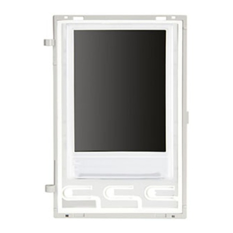
Vimar
Vimar ELVOX 41018 Assembly instructions

Vimar
Vimar ELVOX 41018 User manual
