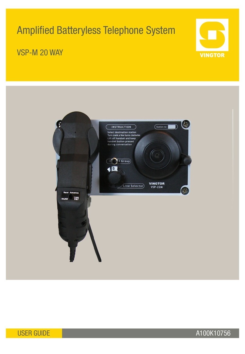
Vingtor Stentofon VSP Series Instruction Manual

VSP-Ex System Installation & User Manual
Doc.no.A100K10872 Page 1
VSP Ex Batteryless Telephone System
Installation & User Manual
TECHNICAL MANUAL
A100K10872

VSP-Ex System Installation & User Manual
2A100K10872
Contents
1BASIC INFORMATION 1
1.1 Revision History 1
1.2 Certificates 1
2GENERAL DESCRIPTION 2
2.1 Introduction 2
2.2 Operating Unit 2
2.3 Buffer Unit 2
3SYSTEM DESCRIPTION 3
3.1 Call from VSP-512 Station (Operative Unit) in Hazardous Area 3
3.2 Being Called in Hazardous Area 3
4INSTALLATION DESCRIPTION 4
4.1 General Installation Instructions 4
4.2 Startup Procedure 4
5SERVICE & MAINTENANCE 4
5.1 General 4
5.2 Approved Spare Parts List VSP-50xx 5
6TECHNICAL DATA 6
6.1 Operative Unit VSP-512 6
6.2 Buffer Units VSP-5004 / VSP-5008 / VSP-5012 6
6.3 Audio Accessories 6
6.4 Marking VSP- 512 7
6.5 Marking VSP-5004 / VSP-5008 / VSP-5012 7
6.6 Ex Components Used 8


VSP-Ex System Installation & User Manual
Doc.no.A100K10872 Page 1
1 Basic Information
1.1 Revision History
Version no.
Date
Author
Status
00
06.03.20
Sen
First version
25.08
ER
Doc.no. VSP-Ex_iu Rev.00 is replaced
with A100K10872 New Template
2.0
22.06.2011
Sen
Add revision status on front and pages Add
supplement to Nemko certificate
3.0
17.07.2015
Sen
Headset VSP-512-PEL w/adapter replaced
by AK5850HS, Cable with switch AK6797
(10mtr.) and AK6799 (20mtr)
Ex relay MK13-222Ex-R replaced by IM1-
22Ex-R2ch. Drawings updated
New template
3.1
14.06.2017
Sen
7 Appendix 7.1Technical drawings
Headset removed from zone 0 on drawing
VSP-5012_sl Rev.04 and VSP-5012_cc2
Rev.04 Changed drawing VSP-IS28-
MK4_wd Rev.01
Declaration of conformity added after
recommendation from Nemko
3.2
5.12.2018
HKL
New Nemko CE Declaration of Conformity
1.2 Certificates
ATEX Certificate Number
Presafe 15 ATEX 6475
IECEx Certificate Number
IECEx PRE 15.0024
Tested according to standards:
EN 60079-0: 2012 and EN 60079-11: 2012 for ATEX
IEC 60079-0: 2011 and IEC 60079-11: 2011 for IECEx CE0470

VSP-Ex System Installation & User Manual
2A100K10872
VSP-512
Select station, press call
for 10 seconds,
giving signal to the station.
Lift of the handset, press
the handset button and
keep it pressed during
the whole conversation.
2 General Description
2.1 Introduction
The Intrinsically Safe Set for VSP consists of:
VSP-5012 Buffer unit for a safe area, and operating unit VSP-512 to be mounted in a hazardous
area.
The VSP-512 can call all other units in the total system.
Alternative:
Buffer unit VMP-5004 / VMP-5008 for safe area, and Operating unit VSP-512 to be mounted in a
hazardous area.
The VSP-512 can call 4 - 8 other units in the total system.
Buffer unit: VSP-5012 VSP-512
Alternative: VSP-5004/VSP-5008
The operative unit VSP-512 is designed for use in a hazardous area: II (1)G Ex ia IIC T4 Ta=60°C
The buffer unit VSP-5012 is designed for use in a safe area: II (1)G [Ex ia] IIC Ta=60°C
2.2 Operating Unit
The Operating Unit VSP-512 enables communication to and from a person located in hazardous
areas. The conversation is possible via the unit handset.
2.3 Buffer Unit
The two Zener barriers MTL 7760ac handle the communication lines.
The relay IM1-22Ex-R2-ch (6 pieces in VSP-5012 and 2-4 pieces in VSP-5004/VSP-5008) provide
for call functions from the operation unit in a hazardous area to the VSP system units in a safe
area.
Other relays provide output for connection of Ex-approved external signaling units operating on
24V DC.
When calling a VSP station in the hazardous area from a VSP station located in the safe area, a
relay K2 to K5 in the buffer opens up for supplied power to the separate call signal device in the
hazardous area.

Installation & User Manual VSP-Ex System
A100K10872 3
3 System Description
3.1 Call from VSP-512 Station (Operative Unit) in Hazardous Area
You may select between 12 (alternative 4 or 8) other stations in the system.
Select the station by operating the station selector switch, and then press the call button for
several seconds, giving a signal to the selected station.
Lift the handset, and press and hold the handset button during the whole conversation.
You can now communicate with full power for guaranteed periods of 20 minutes.
After 20 minutes, you may extend the speech time by pressing the actual call button at the station
front.
3.2 Being Called in Hazardous Area
A received call in a hazardous area is indicated by audible or visible Ex-approved signal unit(s) for
Ex category II 2 G (Zone 1), or horn and sounder for Ex II 1 G (Zone 0), operated and fed with
power via the buffer unit in the safe area.
Lift the handset, and press and hold the handset button during the whole conversation.

VSP-Ex System Installation & User Manual
4A100K10872
4 Installation Description
4.1 General Installation Instructions
The installation cable enters the VSP-512 from the bottom through the K-M20 or K-M12 cable
glands.
This installation cable, coming from the buffer unit in the safe area, terminates inside the station on
the X1 terminal list.
VSP-512 is for wall mounting, and can be installed inside –Ex II 1 G (Zone 0)
The buffer unit VSP5012 and VSP-5004/008 are built into a steel cabinet.
The buffer is for wall mounting and must be located outside the hazardous area - in SAFE area.
The cables to and from the safe area part of the system are connected to the grey terminal plug
located on PC-board PCB-VSP-5012 Plugs P1 to P4.
The cables to and from the VSP-512 located in the hazardous area must be connected to blue
terminal list X10.
See drawings: VSP-5012_sl, VSP-5012_cc1, VSP-5012_cc2, VSP-5012_lo, and VSP-EX_sd
All installations in the hazardous area must be according to the EN 60079-14:2013 standard.
4.2 Startup Procedure
-Complete all wirings as shown in included example drawings VSP-5012_cc1 and
VSP-5012_cc2 or project drawings.
-Power up the system with 24Vdc and check that all PWR lamps on IM1-22Ex-R2ch relays
in buffer unit are lit.
-The 24V DC signal output must be wired to the correct extensions. Strap the relay circuits
on connector P4 (pin 1 to 4) to the actual extension on P3 (pin 1 to 16).
This is usually factory-set according to your specification.
-Test a call from the safe area VSP station to one of the VSP main stations. Check the
sound quality. If the extension is connected to one of the relay outputs, check that there is
24Vdc on terminals P4 (pins 5 to 12) and that the signal unit is working.
-Test a call from one of the VSP-512 stations to the safe area VSP stations. Check the
sound quality.
-If the sound quality is bad, then check whether the wiring is correct, and the shield is
isolated and grounded in terminal 2 on VSP-211-L only.
5 Service & Maintenance
5.1 General
All maintenance and service must be performed by competent personnel with sufficient Ex
knowledge. These persons must take sole responsibility that the system conforms to the required
standards.
Spare parts are listed in the included spare part lists, and must be purchased or approved by
Zenitel.
Installation & User Manual VSP-Ex System
A100K10872 5
Other than changing spare parts, NO modifications to the equipment are allowed.
A Zenitel approved partner must perform any further service and other work than what is described
here.
5.2 Approved Spare Parts List VSP-50xx

VSP-Ex System Installation & User Manual
6A100K10872
6 Technical Data
6.1 Operative Unit VSP-512
Blue Terminal List X1
Blue Terminal List
X1
Microphone Capsule Line
Terminal 1-2
Speaker Capsule Line
Terminal 3-4
Call Out
Terminal 5-18
Ui
2.2V
Inductance
0.75 uH
Inductance
4.3 uH
Uo
9.6 V
Li
200mA
Impedance
150 ohm
Impedance
180 ohm
Lo
22 mA
Pi
0.35W
Po
52 mW
Co
3.6 μF
Lo
70 mH
L/R
674 uH/Ώ
6.2 Buffer Units VSP-5004 / VSP-5008 / VSP-5012
Blue Terminal List X10
Audio Signal
Terminal 1-4
Call Out
Terminal 5-6,7-8,9-10
Uo
2,2V
Uo
9.6 Vac
Io
200mA
Io
22 mA
Po
0.35W
Po
52 mW
Co
100 μF
Co
3.6 μF
Lo
0.91 mH
Lo
70 mH
L/R
71 uH/Ώ
L/R
674 uH/Ώ
6.3 Audio Accessories
Only Ex-certified audio accessories which comply with the input and output values in
sections 6.1 and 6.2 may be used with the Ex Products.
The following Zenitel accessories comply with the input and output values stipulated above, and
are approved for use with the Ex Products:
Ex audio accessories
2330040026
AK5850HS
Ex-Approved Headset with plug **
2330040027
AK6797
Cable with latching switch for headset 10mtr.
1008150030
AK6799
Cable with latching switch for headset 20mtr.
** Headset AK5850HS is only certified for use in ATEX areas (NOT IECEx)

Installation & User Manual VSP-Ex System
A100K10872 7
6.4 Marking VSP- 512
Based on the requirements of zone 0, T4 and the chosen concept of protection, the Ex Product
shall include the following marking:
II (1)G Ex ia IIC T4 Ta=60°C
6.5 Marking VSP-5004 / VSP-5008 / VSP-5012
Based on the requirements of a nonhazardous area, T4 and the chosen concept of protection, the
Ex Product shall include the following marking:
II (1)G [Ex ia] IIC Ta=60°C

VSP-Ex System Installation & User Manual
8A100K10872
6.6 Ex Components Used
Ex Component
Certificate
CENELEC Standard
IECEx Standard
Weidmüller Interface
GmbH & Co. KG,
Empty enclosure
IBExU 13 ATEX 1004X
IECEx IBE 13.0003U
EN 60079-0:2012, EN
60079-7:2007, EN
60079-31:2008
IEC 60079-0:2011, IEC
60079-7:2006, IEC
60079-31:2008
Phoenix contact
GmbH&Co. KG,
Terminal block MUT 2,5
BU
SEV 13ATEX0178U
IECEx SEV 13.0012U
EN 60079-0:2012, EN
60079-7:2007
IEC 60079-0:2011, IEC
60079-7:2006
Measurement
Technology Limited,
MTL7760 ac Series
shunt Zener diode
barriers
BAS 01ATEX7217
IECEx BAS 04.0025
EN 60079-0:2012, EN
60079-11:2012
IEC 60079-0:2011, IEC
60079-11:2011
Hans Turck GmbH & Co.
KG,
Isolating Switch
Amplifier type IM1-
22Ex-R 2ch
TÜV 04ATEX2553
IECEx TUN 06.0006X
EN 60079-0:2009, EN
60079-11:2007
IEC 60079-0:2007, IEC
60079-11:2006

Installation & User Manual VSP-Ex System
A100K10872 9
7 Appendix
7.1 Technical Documentation
Relevant documentation including certificates and declarations of conformity may be downloaded
from: www.zenitel.com/customer-service/library
Document no.
Rev.
Description
VSP-EX_sd
04
System Description
VSP-5012_sl
04
Single line diagram
VSP-5012_cc1
00
Cable connection diagram
VSP-5012_cc2
04
Cable connection diagram
VSP-IS28-MK4_wd
01
Wiring of VSP-5012 for 2x Sounder
VSP-5012_lo
05
Layout buffer unit VSP-5012/ 5008/ 5004
Product label VSP-Ex.pl
05
Product label VSP-512 & VSP-5012/ 5008/ 5004
A100K10446
27.01.2015
Datasheet buffer unit VSP-5012
VSP-5012_wd
03
Wiring diagram for VSP-5012
A100K10446
27.01.2015
Datasheet buffer unit VSP-5008
VSP-5008_wd
01
Wiring diagram for VSP-5008
VSP-5004_ds
27.01.2015
Datasheet buffer unit VSP-5004
VSP-5004_wd
01
Wiring diagram for VSP-5004
VSP-512_ds
27.01.2015
Datasheet for VSP-512
VSP-512_lo
04
Layout telephone VSP-512
VSP-512_wd
02
Wiring diagram for VSP-512
A100K11514
27.01.2015
Datasheet Headset AK5850HS
A100K11569
02.02.2015
Connection & User manual AK6797 & AK6799 Cable with
toggle switch for headset AK5850HS
VSP-Ex-CE.04.pdf
5.12.2018
Declaration of Conformity - CE

VSP-Ex System Installation & User Manual
10 A100K10872

Installation & User Manual VSP-Ex System
A100K10872 11

VSP-Ex System Installation & User Manual
12 A100K10872

Installation & User Manual VSP-Ex System
A100K10872 13

VSP-Ex System Installation & User Manual
14 A100K10872

Installation & User Manual VSP-Ex System
A100K10872 15

VSP-Ex System Installation & User Manual
16 A100K10872
This manual suits for next models
4
Table of contents
Other Vingtor Stentofon Telephone System manuals
Popular Telephone System manuals by other brands

ADC
ADC InterReach Office 105880AE Specification sheet

RCA
RCA 25450 user guide

Toshiba
Toshiba Strara CTX Series Installation and maintenance manual

AT&T
AT&T Definity 6402D user guide

Samsung
Samsung OFFICESERV 100 Series installation manual

Lucent Technologies
Lucent Technologies MERLIN LEGEND Release 5.0 System planning

Polycom
Polycom SpectraLink 6000 System Maintenance and Diagnostics

Nortel
Nortel Meridian Meridian 1 General maintenance information

3Com
3Com SuperStack 3 NBX Administrator's guide

BT Quantum
BT Quantum 8568 user guide

Avaya
Avaya 4600 Series installation manual

Radio Shack
Radio Shack Automatic Desktop Dialer user manual