Gate Stop - 1 pc Gate - 1 pc
MODEL 2008GP
MODEL 2008GPMODEL 2008GP
MODEL 2008GP
-
--
- GATE PACKAGE
GATE PACKAGE GATE PACKAGE
GATE PACKAGE
for mode s 2008AF
for mode s 2008AF for mode s 2008AF
for mode s 2008AF -
--
- 2008CE
2008CE 2008CE
2008CE -
--
- 2008G2D
2008G2D 2008G2D
2008G2D
Poo Entry Systems & Decks
Poo Entry Systems & DecksPoo Entry Systems & Decks
Poo Entry Systems & Decks
IMPORTANT INSTRUCTIONS
IMPORTANT INSTRUCTIONSIMPORTANT INSTRUCTIONS
IMPORTANT INSTRUCTIONS: Read all instructions carefully & completely to become familiar ith
: Read all instructions carefully & completely to become familiar ith : Read all instructions carefully & completely to become familiar ith
: Read all instructions carefully & completely to become familiar ith
parts, assembly, safety and proper use of this product. Failure to follo these instructions may
parts, assembly, safety and proper use of this product. Failure to follo these instructions may parts, assembly, safety and proper use of this product. Failure to follo these instructions may
parts, assembly, safety and proper use of this product. Failure to follo these instructions may
result in serious personal injury. SWIM RESPONSIBLY & SAFELY !
result in serious personal injury. SWIM RESPONSIBLY & SAFELY !result in serious personal injury. SWIM RESPONSIBLY & SAFELY !
result in serious personal injury. SWIM RESPONSIBLY & SAFELY !
TOOLS REQUIRED
TOOLS REQUIREDTOOLS REQUIRED
TOOLS REQUIRED: 7/16" socket
: 7/16" socket : 7/16" socket
: 7/16" socket -
--
- nut driver, rench or pliers, Phillips (star) scre driver, pencil, 1/8"
nut driver, rench or pliers, Phillips (star) scre driver, pencil, 1/8" nut driver, rench or pliers, Phillips (star) scre driver, pencil, 1/8"
nut driver, rench or pliers, Phillips (star) scre driver, pencil, 1/8"
drill bit & drill + a pad lock for security hen the pool is not in use
drill bit & drill + a pad lock for security hen the pool is not in usedrill bit & drill + a pad lock for security hen the pool is not in use
drill bit & drill + a pad lock for security hen the pool is not in use
SAFETY INSTRUCTIONS & PROPER USE
SAFETY INSTRUCTIONS & PROPER USE SAFETY INSTRUCTIONS & PROPER USE
SAFETY INSTRUCTIONS & PROPER USE -
--
- ASSEMBLY & INSTALLATION
ASSEMBLY & INSTALLATION ASSEMBLY & INSTALLATION
ASSEMBLY & INSTALLATION
•
These pool entry systems have a 300 lb load capacity
These pool entry systems have a 300 lb load capacity These pool entry systems have a 300 lb load capacity
These pool entry systems have a 300 lb load capacity -
--
- one person
one person one person
one person -
--
- hen properly installed
hen properly installed hen properly installed
hen properly installed
•
These entry systems are designed & intended for use ith an above ground pool only (flat bottom)
These entry systems are designed & intended for use ith an above ground pool only (flat bottom)These entry systems are designed & intended for use ith an above ground pool only (flat bottom)
These entry systems are designed & intended for use ith an above ground pool only (flat bottom)
•
Your above ground pool has shallo ater
Your above ground pool has shallo ater Your above ground pool has shallo ater
Your above ground pool has shallo ater -
--
- absolutely NO DIVING or NO JUMPING into the pool
absolutely NO DIVING or NO JUMPING into the pool absolutely NO DIVING or NO JUMPING into the pool
absolutely NO DIVING or NO JUMPING into the pool
•
This product conform to the latest revisions of the ANSI/APSP recommended standards for
This product conform to the latest revisions of the ANSI/APSP recommended standards forThis product conform to the latest revisions of the ANSI/APSP recommended standards for
This product conform to the latest revisions of the ANSI/APSP recommended standards for
above ground/on ground s imming pool ladders
above ground/on ground s imming pool ladders above ground/on ground s imming pool ladders
above ground/on ground s imming pool ladders
•
For entry & exit of the pool, hen climbing, face steps at all times. Use handrails for safe climbing
For entry & exit of the pool, hen climbing, face steps at all times. Use handrails for safe climbingFor entry & exit of the pool, hen climbing, face steps at all times. Use handrails for safe climbing
For entry & exit of the pool, hen climbing, face steps at all times. Use handrails for safe climbing
•
These systems are designed for use by one person at all times
These systems are designed for use by one person at all timesThese systems are designed for use by one person at all times
These systems are designed for use by one person at all times
•
These entry systems are designed ith a protecting gate system
These entry systems are designed ith a protecting gate system These entry systems are designed ith a protecting gate system
These entry systems are designed ith a protecting gate system -
--
- NEVER use system ithout gate attached & fully
NEVER use system ithout gate attached & fully NEVER use system ithout gate attached & fully
NEVER use system ithout gate attached & fully
functional. When pool is not in use, make certain gate is securely closed, latched & locked to prevent un anted entry
functional. When pool is not in use, make certain gate is securely closed, latched & locked to prevent un anted entryfunctional. When pool is not in use, make certain gate is securely closed, latched & locked to prevent un anted entry
functional. When pool is not in use, make certain gate is securely closed, latched & locked to prevent un anted entry
•
Locate entry system on a solid base and free from high traffic areas around the pool
Locate entry system on a solid base and free from high traffic areas around the poolLocate entry system on a solid base and free from high traffic areas around the pool
Locate entry system on a solid base and free from high traffic areas around the pool
•
Secure entry system to top rail of pool for greater stability and safety
Secure entry system to top rail of pool for greater stability and safetySecure entry system to top rail of pool for greater stability and safety
Secure entry system to top rail of pool for greater stability and safety
•
Keep top platform and treads free from obstructions to avoid possible injury. Do not secure any items to the entry systems.
Keep top platform and treads free from obstructions to avoid possible injury. Do not secure any items to the entry systems. Keep top platform and treads free from obstructions to avoid possible injury. Do not secure any items to the entry systems.
Keep top platform and treads free from obstructions to avoid possible injury. Do not secure any items to the entry systems.
Such objects (e.g. thermometers, play toys, ropes) may create a potential for tripping or entrapment
Such objects (e.g. thermometers, play toys, ropes) may create a potential for tripping or entrapmentSuch objects (e.g. thermometers, play toys, ropes) may create a potential for tripping or entrapment
Such objects (e.g. thermometers, play toys, ropes) may create a potential for tripping or entrapment
•
NEVER ALLOW CHILDREN TO SWIM UNATTENDED
NEVER ALLOW CHILDREN TO SWIM UNATTENDED NEVER ALLOW CHILDREN TO SWIM UNATTENDED
NEVER ALLOW CHILDREN TO SWIM UNATTENDED -
--
- Nothing replaces parental supervision
Nothing replaces parental supervision Nothing replaces parental supervision
Nothing replaces parental supervision
•
Install this gate for pool entry system as per the manufacturer’s instructions. Do not deviate from these instructions
Install this gate for pool entry system as per the manufacturer’s instructions. Do not deviate from these instructions Install this gate for pool entry system as per the manufacturer’s instructions. Do not deviate from these instructions
Install this gate for pool entry system as per the manufacturer’s instructions. Do not deviate from these instructions
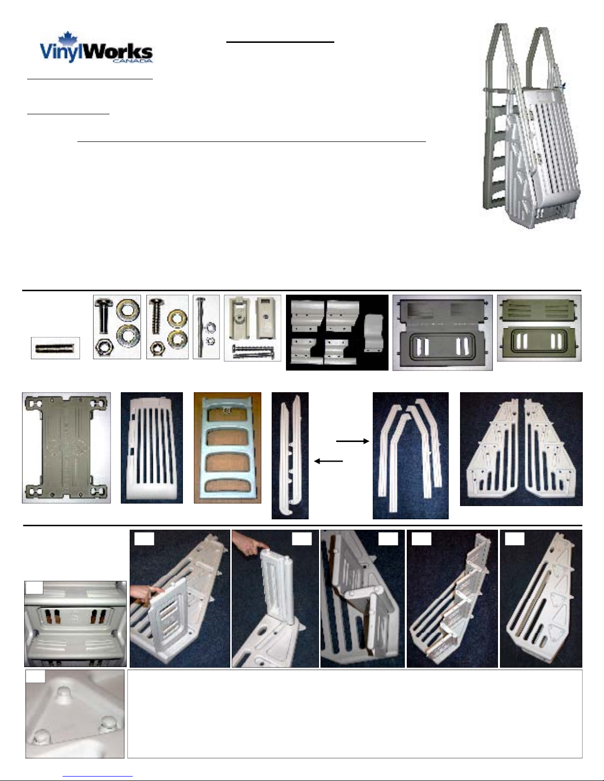
IDENTIFY PARTS
IDENTIFY PARTSIDENTIFY PARTS
IDENTIFY PARTS
Outer Hinge
(2 pcs)
(large)
The gate & gate components are packaged different for different units - make
certain you have all appropriate cartons and parts to complete your chosen
pool entry system or deck assembly & installation (Model 2008AF - 2008CE or
2008G2D used ith SD & FD decks). Familiarize yourself ith all parts and read
instructions before starting assembly & installation. If you notice any parts
damaged or missing please contact our customer service department for
assistance @ 877-VINYL WK.
Hard are &
Instructions
Included
¾"
1/4"
Round
3/16"
Round
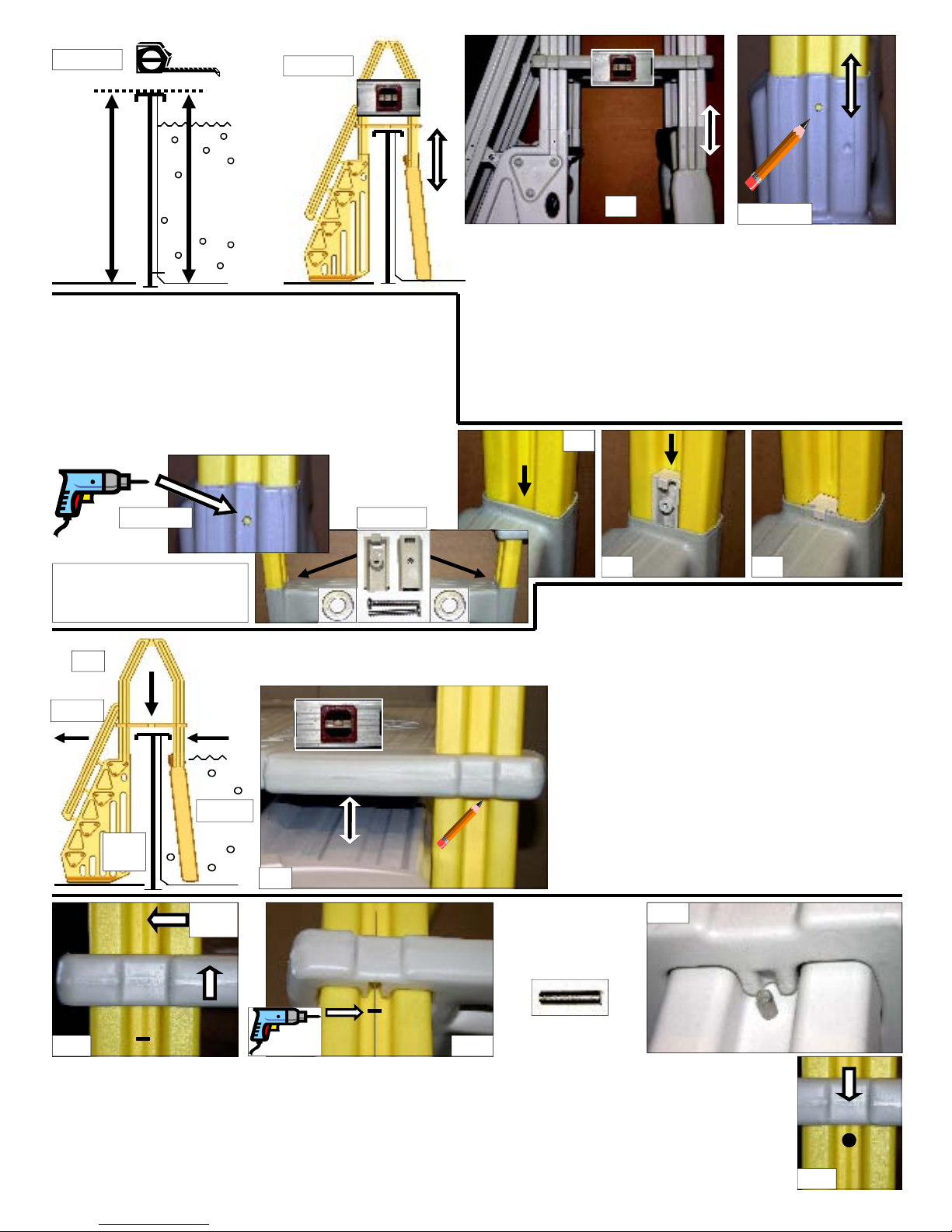
Measurement
Guide
Inner Hinge
(2 pcs)
(small)
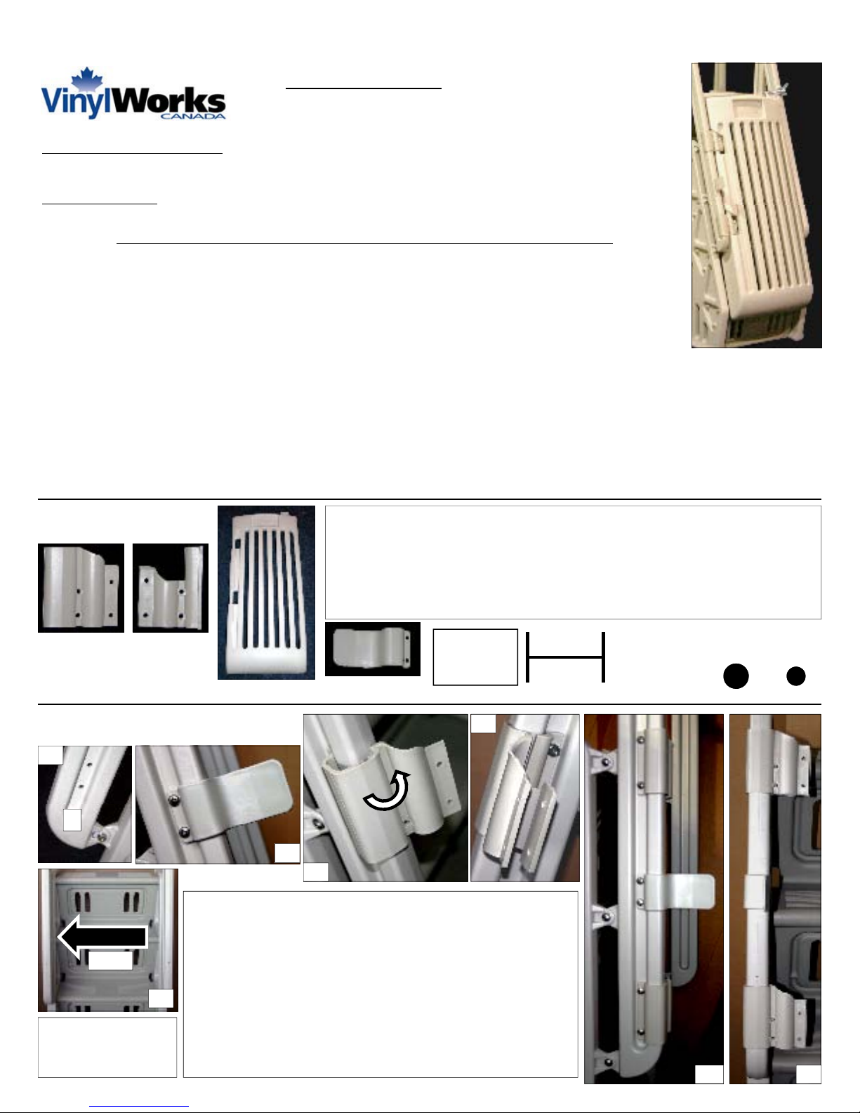
POSITION HINGES & GATE STOP
POSITION HINGES & GATE STOPPOSITION HINGES & GATE STOP
POSITION HINGES & GATE STOP
The LEFT lo er handrail on the exterior portion of the entry
has holes to accept the hinges & gate stop (see 1.1 & 1.2).
Begin by securing the gate stop in place. Fit the stop on the
outside face of the handrail over the center t o holes - it is
form fitting (see 1.3). Secure using t o 1/4 x 3/4" bolts,
ashers on inside & nuts. Tighten hard are. Fit the outer
hinges in place around handrail. Like ise, they are form fitting
and ill snap around handrail (see 1.4). The inner hinge fits on
the inside of handrail and aligns ith the large on the outside.
Use t o 1/4 x 3/4" bolts, ashers & nuts on the inside face and
secure LOOSELY in the back t o holes, only FINGER TIGHT
(see 1.5-1.7). See 1.6 & 1.7 for proper placement of parts
L
1.5
1.6
1.2
LEFT
1.1
1.3
1.7
1.4
READ ALL
INSTRUCTIONS
CAREFULLY