Vinyl Works SD User manual

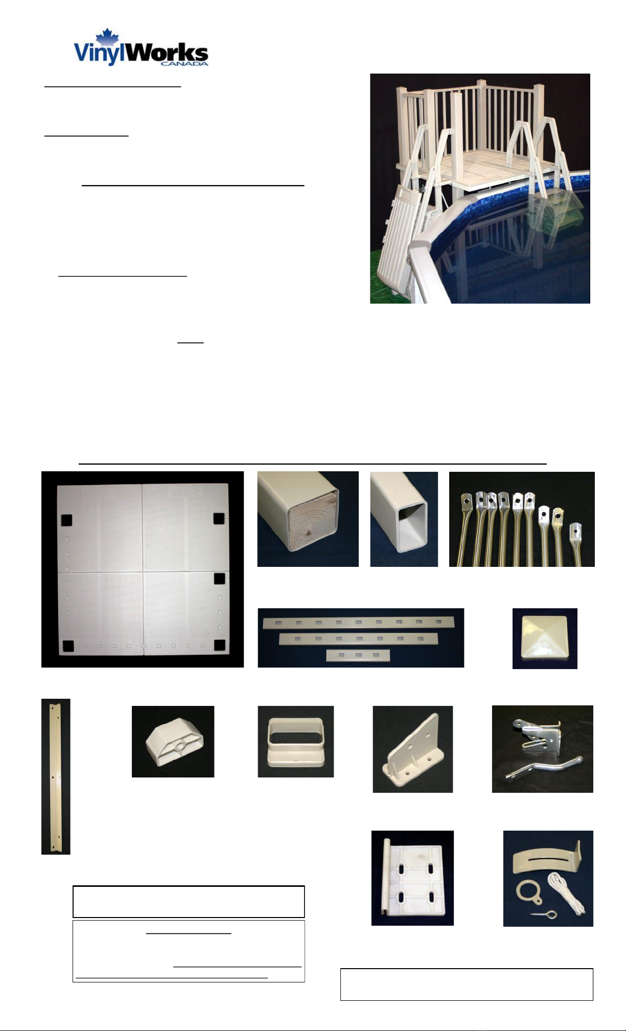
MODEL SD - 5ft x 5ft RESIN POOL DECK
(with In-Pool & Ground to Deck Steps)
IMPORTANT INSTRUCTIONS: Read all instructions carefully &
completely to become familiar with parts, assembly, safety &
proper use of this product. Failure to follow these instructions may
result in serious personal injury. Review with all using this product
TOOLS REQUIRED: sockets, wrench or nut driver, measuring tape,
square, phillips (star) screwdriver, drill & 1/8" & 1/4" drill bits,
pencil, level & hand saw + five (5) 16" x 16" x 2" concrete blocks
• This resin pool deck & step systems has a 1,000 lb load capacity
- four persons max - when properly installed
• Pool steps have a 300 lb load capacity - one person
• The step systems supplied are designed & intended for use with
this resin pool deck - do not change or deviate with another step
• Your above ground pool has shallow water - absolutely
NO DIVING or NO JUMPING from deck into pool
• This product conforms to the latest revisions of the APSP & ANSI
standards for above ground pool decks & entry systems
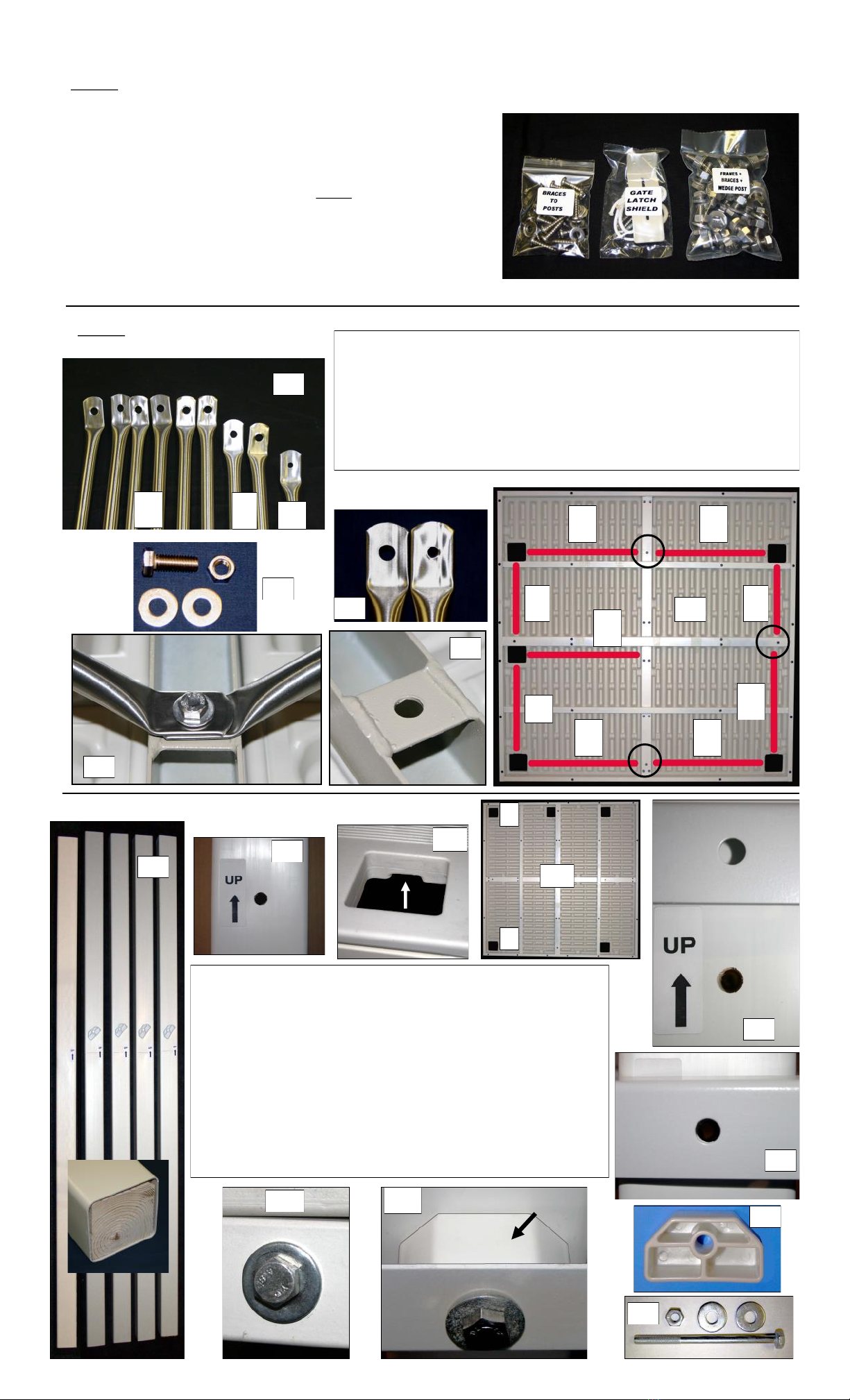
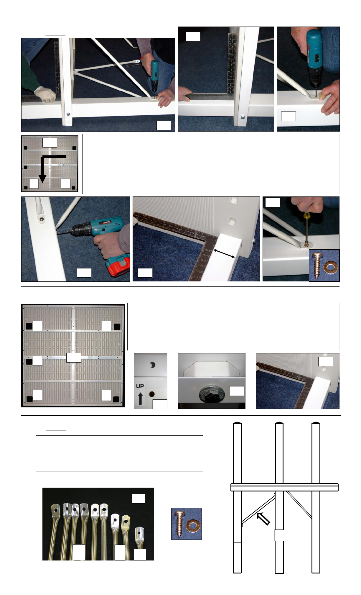
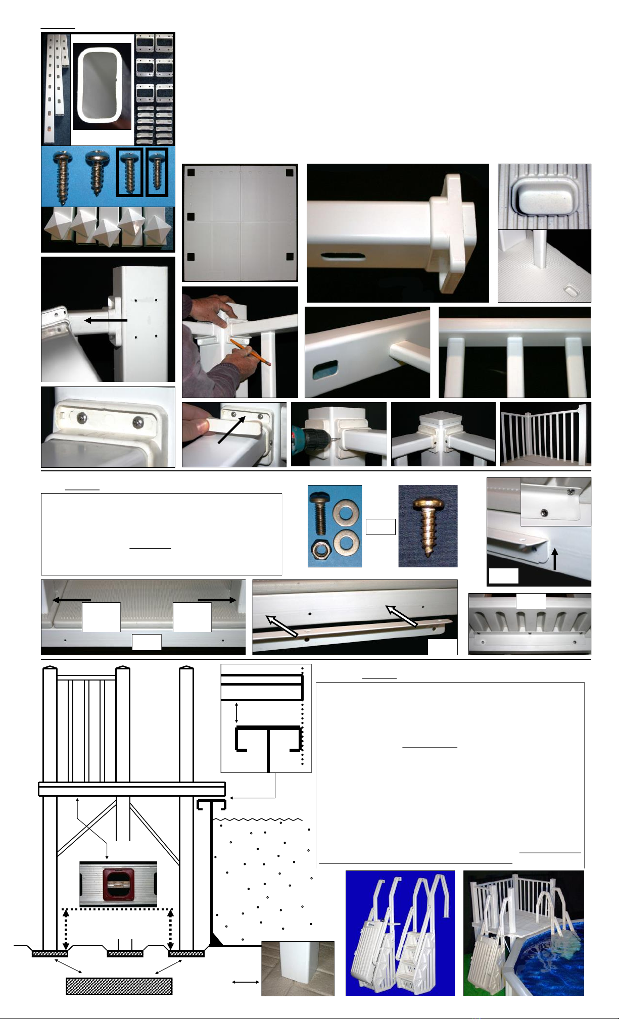
ASSEMBLY & INSTALLATION - IDENTIFY PARTS & COMPONENTS & HARDWARE
SAFETY INSTRUCTIONS & PROPER USE
• For entry to & exit from the pool & deck, face pool steps at all times
• Be aware - chairs or lounges with sharp or pointed legs may damage deck surface
• The ground to deck entry MUST be used with the gate installed & fully functional. Ensure the gate is secure &
locked when the pool is not in use - AT ALL TIMES (Lock not included)
• Locate the ground to deck entry system on a solid base for greater stability & away from high traffic areas
• Secure both entry systems to deck for stability and safety as per instructions
• Keep handrails and treads of both step systems free from obstructions to avoid possible injury. Do not secure any
items to the step systems. Such objects may create a potential for tripping, entanglement and drowning
• NEVER ALLOW CHILDREN TO SWIM UNATTENDED - Nothing replaces parental supervision at all times
• Assemble & install this deck & step systems as per the manufacturer’s instructions. Do not deviate from these
instructions - ALWAYS SWIM SAFELY - NO DIVING & NO JUMPING into the pool - serious injury can occur
Deck Platform & Frame (pre-attached)
G2D
Entry
Support
Angle Handrail Connector
Brackets ( 6 pcs )
Post Braces
( 9 pc )
Handrails
( 3 pcs)
Posts
(5 Long pcs)
Post Caps
( 5 pc )
Post
Spacers
( 5 pcs ) G2D Handrail
Connectors ( 2 pc )
In-Pool Step
Base Plate
(2 pcs)
THE MODEL SD 5x5 RESIN DECK COMES
PACKAGED IN FIVE (5) CARTONS
IMPORTANT NOTE
These instructions are specific to this model of deck.
Instructions included with steps may differ slightly for
other applications. Please follow these deck
instructions closely & do not deviate from them. Make certain to familiarize yourself with all parts before starting
assembly of your deck. If you notice any parts damaged or missing,
please contact our customer service for assistance: 877-VINYL WK
Pickets
(19 pcs)
Gate Latch &
Striker ( 1 set )
Gate Latch
Shield ( 1 set )

Step 2 - Attach Brace Supports Identify & sort braces by length. There are six medium (M), two short (S)
and one special (*) braces (see 2.1). Separate five 3/8" x 1" long bolts &
3/8" small washers & nuts from hardware kit (see 2.2). Lay deck platform
face down & position braces (see 2.3). Two braces are secured to one bolt
position and identified by the circles (see 2.3 & 2.5). Fit bolt (+ washer)
through the large hole in end of the braces and through hole on steel frame
(see 2.4 & 2.5 & 2.6) Secure using washer & nut from bottom. Tighten
hardware to snug only. DO NOT ATTACH THE SPECIAL BRACES UNTIL
STEP 9.
2.2
Step 3 - Position & Attach Long Support Posts
2.6
S
M
S
M
M
M
M
M
*
2.3
Select all five 96" long support posts (see 3.1). Note each post is
marked with direction arrow (see 3.2). Stand deck platform with
braces on it’s edge so the back legs are towards the left (see 3.4).
From bottom to top of platform, fit a support post through the post
hole in platform (see 3.3 above). Start with the post towards the
bottom (see 3.4 - post hole “A”). Make certain the direction arrow
and hole in the post is facing the bolt hole in the platform frame (see
3.5). Position the post so the hole in the post is centered with the
bolt hole in the frame (see 3.6). Using a post spacer (see 3.7) & a
3/8" x 6" bolt and washer (see 3.8), position spacer between post &
frame & pass bolt through holes in frame, spacer & post (see 3.9).
Secure only finger tight using washer & nut so post can move
slightly (see 3.10). With deck still standing on edge, repeat above
procedure for support post located at position “B” in 3.4 above.
3.3
3.4
B
A
C
K
F
R
O
N
T
A
B
3.2
3.5
3.7
3.8
3.6
SPACER
3.9
3.10
3.1
2.5
Step 1 - Organize & Get Ready for Assembly - Separate Hardware & Identify
Your pool deck is packaged in five cartons total. Familiarize
yourself with all components (see parts layout on page 1).
Open the hardware kit (bag) and arrange hardware bags,
parts and pieces. Most hardware is individually packaged and
labelled for easy identification (see 1.1). NOTE: the pool steps /
cartons (boxes 2 & 4) include hardware as well. Follow
hardware layout included for proper identification and usage.
A measurement guide on the hardware layout can be used to
verify length. All hardware included is 18.8 stainless steel (302
-304 stainless) except the gate latch & striker bar.
1.1
2.1
*
S
M
2.4

Step 6 - Attach Remaining Special Post Brace
Select remaining special post brace (6.1). Position brace
between posts B and E and shown in 6.2. Similar to Steps 4 and
5 above, secure both ends of brace to support posts using
#14x1"screws and washers provided (6.3). Make certain to
square posts to deck frame (5.4 above) so they are plumb.
With deck still on edge, gently rotate deck 90 degrees to the left, counter-clockwise (see 4.1). This
way, first two posts will be towards ground and easy to work with. Starting with post in position B
(see 4.1 & Step 3 previously) use a square to be sure the post is plumb (square) to the deck
platform (4.2 & 4.3). Holding post in place, drill a 1/8" pilot hole in center of post, through eye of
brace (see 4.2 & 4.4). Secure using a #14 x 1" screw and 1/4 washer (see 4.5). Similarly, for the
second brace, use square to make sure post is plumb in opposite direction (see 4.6) & drill pilot
hole through eye of brace (see 4.7). Secure using a screw & washer as in 4.5. Repeat procedure
for support post in position A (see 4.1 & Step 3 previously). Make certain all screws are tight into
posts. Once braces securely in place, tighten post bolts (3/8" x 6" - from Step 3 - 3.9 & 3.10)
4.64.7
Step 4 - Secure Braces to Posts
4.4
4.2
4.3
4.5
4.1
B A
Step 5 - Position & Attach Remaining Posts & Braces
5.1
B A
C D
FRONT OF DECK - TO POOL
5.4
As outlined in Steps 3 & 4 previously, position, attach & secure remaining long
support posts & braces to deck platform (see 5.1 for position C, D & E).
Remember, make certain the direction arrow & hole on the posts are facing bolt
hole in the deck (5.2) & be sure to use post spacer (5.3). Before attaching brac-
es, make certain posts are plumb (square) to deck platform (see 5.4). When com-
plete & in place, secure & tighten all hardware (brace screws & post bolts).
Stand the deck on it’s support posts, in the upright position.
5.2
5.3
POST SPACER
6.2
E
6.3
B E
6.1
*
S
M

Step 7 - Attach Handrails Gather parts for handrails (see 7.1 - handrails, pickets, connectors & covers, screws & post
caps). There are three different lengths of handrails - small (S), medium (M) and large (L).
Note positioning of the three handrails (see 7.2). Fit a handrail connector on both ends of all
three handrails (see 7.3). Make certain large, flat surface of connector is towards end of
rail. Insert pickets, section by section (S-M-L), into molded pockets of deck surface (see
7.4). Fit tops of pickets into precut holes in appropriate handrails (see 7.2 & 7.5 & 7.6). Slide
connectors to ends of rails, towards posts. Center connectors against posts and with
pencil, mark holes in connectors on the posts (see 7.7). Once all connectors marked, push
rail & connector out of the way and drill a pilot hole using a 1/8" bit at all pencil marks (see
7.8). Secure all connectors in place using the #8 x 3/4" screws provided (see 7.9 & 1.2).
Snap screw cover caps in place (see 7.10). To keep handrails from moving, drill a 1/8" hole
through side of connector & handrail (see 7.11). Secure using #6 x 5/8" screws provided
(see 7.1 & 1.2 & 7.12). Fit post caps and your railing is complete (see 7.12 & 7.13)
7.1
S
M
L
7.2
7.3
7.4
7.5
7.6
7.7
7.8
7.9
7.10
7.11
7.12
7.13
Step 9 - Position Deck Against Pool
Position deck against pool at desired location. The front of
the deck is designed to cantilever the top rail of the pool
sufficient only to prevent stepping on top rail & to eliminate
gap between deck & top rail (see 9.1.1 & 9.3). The front
edge of the deck should not protrude past the inside face of
the top rail. It is IMPORTANT to leave a 1" to 1½" gap
between the top rail of the pool & the underside of the deck
so the pool is not bearing the weight of the deck. Also, it
allows space to install the winter cover. The five support
posts should sit on 16" square x 2" thick concrete blocks
(see 9.1.2). These concrete footings must be leveled and
set at the proper elevation (see 9.1.3) to maintain proper
clearance between deck & pool. Set elevation of blocks
rather than cutting posts. Once complete, make certain
deck is level, stable & does not rock. Continue with
assembly & installation of steps (see 9.2). ABSOLUTELY
NO DIVING or JUMPING from deck into pool
LEVEL
CONCRETE
BLOCK
POOL
WALL
9.2
9.3
TOP RAIL
9.1.2
9.1.3
9.1.1
1" to 1½"
FRONT OF DECK
Step 8 - Attach Entry Support Angle
Select two 1/4 x 3/4" bolts & three #14 x 3/4 screws
(see 8.1). Position the G2D entry support angle in
place & align the two holes (see 8.2 & 8.3 & 8.4).
Secure angle to deck frame using bolts, washers
both sides & nuts. TIGHTEN. The angle will be used
for the G2D assembly & installation (see 8.5 + accom-
panying instruction page for G2D entry)
8.5
8.4
8.3
LONG
POST
LONG
POST
UP
8.2
8.1
Table of contents
Other Vinyl Works Lighting Equipment manuals
Popular Lighting Equipment manuals by other brands

Larson Electronics
Larson Electronics EPL-FL1524-LED Series instruction manual

ADJ
ADJ ULTRA GO PAR7X User instructions

Daintree
Daintree GE current Tetra PowerStrip Snap DS installation guide

Bresser
Bresser BR-S60 RGB instruction manual

InterTest
InterTest iShot UV/White LED Light Source Kit manual

Color imagination
Color imagination LEDZOOM 1915F user manual