5
This Instruction Manual must be read carefully before starting to use your tube bender. lt contains
important information about installation, use, safety and maintenance of the machine in order to prevent any
accidents or technical incidents.
Keep this document in a safe place.
1.
SAFETY
1.1
General Instructions
•
Read and keep the attached safety instructions for the electrical tool.
•
Read all instructions and the following recommandations.
•
Avoid accidents by using protective equipment such as goggles, gloves, safety shoes, etc.
•
Carry the machine using the handle built into the casing, never use the motor handle.
•
Put the machine away in its box to transport it and protect it from shocks.
•
Never expose the tube bender to the rain.
•
Make sure that the capacity of your extension cable is 16 A and that it is always in perfect condition.
•
Keep the cable away from moving parts.
•
Do not pull on the cable to unplug it.
•
Do not drag or carry the tube bender using the cable.
•
Stop the tube bender immediately if there are any electrical or mechanical problems.
•
Do not take the battery out when bending.
•
Do not press on the switch when changing forms or during transport.
•
When bending, do not bring your hand close to the form.
•
Do not disassemble the tube bender.
1.2
Operating safety
The machine is provided with :
•
A pusher switch that stops bending immediately at any time.
2.
INSTALLATION
2.1
Electrical connection
Insert the electrical plug into a 230 V, 10 A, 50-60 Hz single phase network protected by a dierential circuit
breaker.
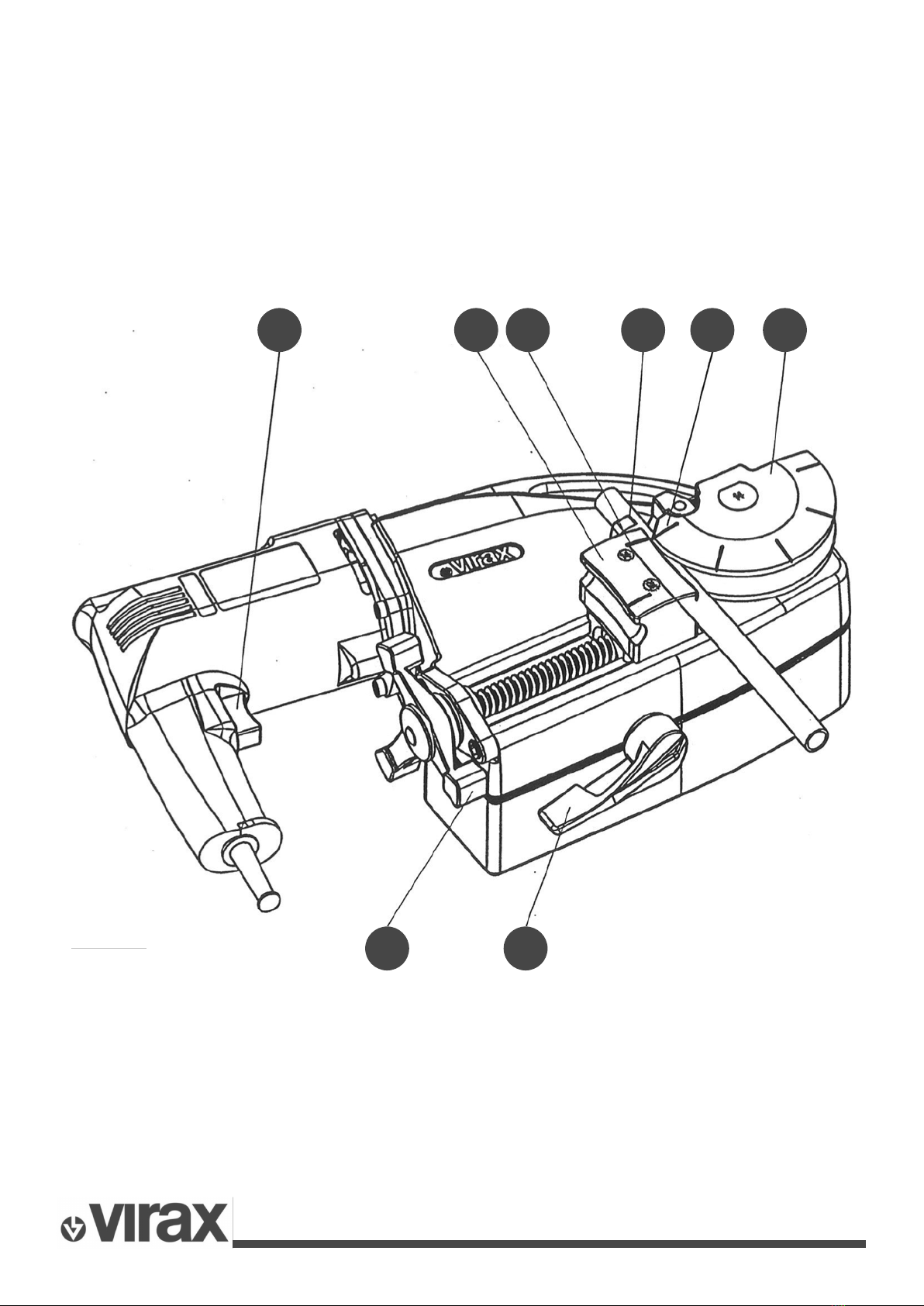
2.2
Bending Tube Ø10 to Ø22 : speed : H Tube Ø25 to Ø28 : speed : L
•
Disengage the bending mechanism by pushing lever 5 down.
•
Place form 6 on the output shaft, search for the indexing position at which hook 7 is placed on the
slide side, by rotating the form manually.
•
Position the mating form 8 on its pivot and rotate until the mark corresponding to the tube to be bent
is on the hook side.
•
lnsert the tube to be bent in the groove of the form.
•
Open hook 7 if necessary to facilitate placement of the tube, and close the hook after placement.
•
Bring the mating form into position untilthe tube is moderately tightened by screwing in hand wheel 9.
Very important:
The rst mark 6a of the form must correspond to mark 8a on the mating form.
•
Press switch 4 to bend, while lifting the mechanism engagement lever 5.
•
Control the bending speed from 0 to the maximum by pressing more or less on the switch.
•
Marks engraved on the form make it easier to produce the required bending angle. Allow for the
bending speed and the elastic return of the tube.
•
Release switch 4 at the end of bending.
•
Retract the mating form by unscrewing hand wheel 9.
•
Disengage the bending mechanism by pushing lever 5 down.
3.
MAINTENANCE
•
Frequently check that the cable and the plug are in good condition.
•
Remove dust frequently and keep motor and charger aeration openings clean an unobstructed.
•
Do not insert sharp objects.
•
Compressed air cleans more eciently.
•
Sorne cleaning products and solvants can damage plastic parts.
•
Excessive sparks on the commutator are usually a sign of excessive brush wear.