Viridian EV EcoLite Basic User manual
Iss 1 - May 2018 Page 1 of 14
Viridian EV is a trading name of EcoHarmony Ltd.
Guidance to Installers of
Viridian EV EcoLite charge point

Iss 1 - May 2018 Page 2 of 14
Viridian EV is a trading name of EcoHarmony Ltd.
This guide is intended to instruct in the proper installation of a Viridian EV EcoLite charge point. Please
note that when installing this equipment care must be taken to ensure that all local and national safety
and planning requirements are met.
INSTALLATION OF THIS EQUIPMENT SHOULD ONLY BE CARRIED OUT BY A
FULLY QUALIFIED INDIVIDUAL. VIRIDIAN EV ACCEPTS NO RESPONSIBILITY FOR
DAMAGE CAUSED BY IMPROPERLY INSTALLED EQUIPMENT.
THIS CHARGE POINT IS PROTECTED BY WEATHERPROOF COAT THAT WILL BE
COMPRIMISED IF HOLES ARE DRILLED. DRILLING ANY HOLES FOR MAINS INLET
WILL VOID THE WARRANTY
Cautions and Dangers
This guide contains several instructions to which the following symbols have been attached. Failure to
comply with instruction could result in:
DANGER Indicates where failure to comply with instructions will cause death or serious
injury.
WARNING Indicates where failure to comply with instructions could lead to death or
serious injury.
CAUTION Indicates where failure to comply with instructions could lead to minor or
moderate injury.
Understanding the model number
E07-T2S-32A-I-W-1P_rcd
Approximate
maximum available
power in kW
i.e 7kW
Series indicator
i.e. EcoLite
Connector Type
i.e Type 2
Outlet style i.e
Socket
Maximum Available
Current per phase
i.e. 32A
Number of phases
i.e. Single Phase
Indicates
integrated SLS or
not
Style indicator, i.e.
White
Iss 1 - May 2018 Page 3 of 14
Viridian EV is a trading name of EcoHarmony Ltd.
WARNING
The charge point is designed for electric vehicle (EV) charging only. It is designed to only allow the flow
of electricity once an EV is connected and correct communication is established. Any tampering of the
charge point to allow the flow of electricity at any times other than this will present a risk of electric
shock.
CAUTION
The Charge point is covered by a manufacturer’s parts and labour warranty (return to base). Alterations
to the charge point that are not permitted will invalidate this warranty.
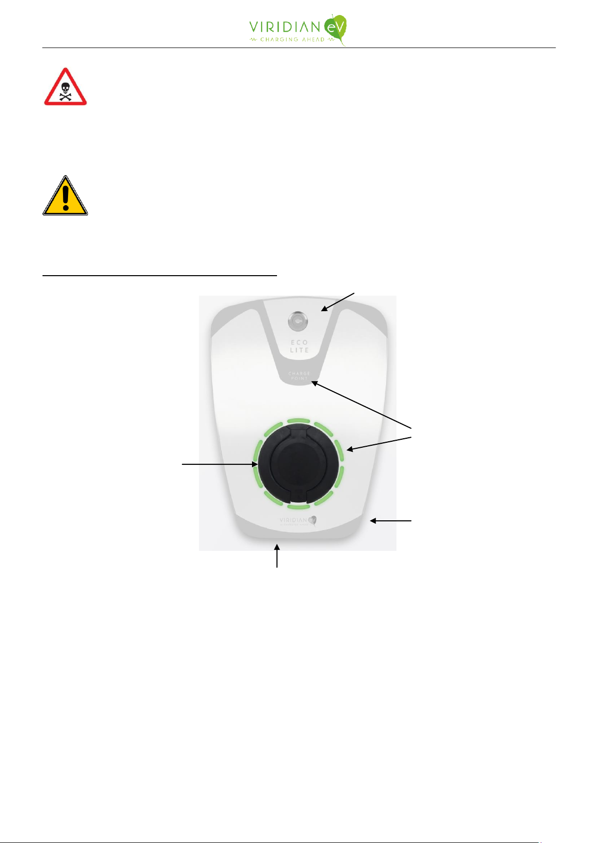
Fig. A - Charge point external features
1. Socket outlet (for Free/Socket versions)
2. Integrated electrical protection suitable for local regulations
3. Status LED text and halo
4. Identification label (side)
5. Electrical protection access panel & key-lock
6. Socket weather drain tube (bottom)
3
1
4
5
6

Iss 1 - May 2018 Page 4 of 14
Viridian EV is a trading name of EcoHarmony Ltd.
Fig. B –Identification/serial label breakdown
Mounting of the charge point
The charge point should be mounted vertically on either a post or a wall. The position of the charge
point should allow all main functions of the charge point to be accessible between 750mm and 1200mm
of the ground in accordance with BS8300:2009, unless otherwise instructed not to. The charge point has
four mounting holes (See Annex 3) that are accessible by removing the enclosure lid. An A3 drill
template, supplied and available online viridianev.co.uk/resources, can be used to aid in preparing
mounting points.
Fig. C - Internal components *
1. Contactor
2. Electrical protection
3. Mains input Earth terminal block
4. EcoLite controller board
5. Socket outlet (Free/Socket versions)
6. Main enclosure earth tag
7. Brightness config. DIP switch
8. Current/SLS config. DIP switch
*contents may vary depending on unit
configuration
Model
Number
Electrical & IP
information
Serial
Number

Iss 1 - May 2018 Page 5 of 14
Viridian EV is a trading name of EcoHarmony Ltd.
Installation method
DANGER
Installation requires access to the properties electrical consumer unit. Ensure that power
to it is isolated before commencing any work.
WARNING
Due to the high and constant current draw, the charge point must be installed on a dedicated spur
within the consumer unit.
CAUTION
The charge point must be installed in accordance with all current safety and legislative requirements
relevant to the location to which it is being installed. If any of the actions listed by the installation
method described below contravene current safety and legislative requirements, they MUST be adjusted
to meet the required standard. If that is NOT possible they MUST NOT be done.
THE INSTALLER MUST ENSURE THE CHARGE POINT IS CORRECTLY EARTHED
It is recommended but not required that an isolation switch should be located near the charge point.
The enclosure lid is removed by removing the 4 black external security-torx screws. A T20 security-
torx driver is required. When the lid is removed, be sure to remove the earth wires from the tabs
inside.
Install a MCCB within the consumer unit that is suitably rated for the charge point(s) that is being
installed –reference the identification label or DIP switch setting & current configuration annex to
confirm
Choose one of the entry points (rear or bottom) and remove blind grommet for wiring mains into
the unit. Ensure suitable cable gland is used for the application/location of charge point.
The charge point should be secured to a wall or post as described on page 4.
If required, set the maximum current output for the unit using the current configuration DIP switch
(Fig. C –8). The configuration should be set to match the protective devices upstream. The default
leaving the factory is 32A. See Current Configuration table on Annex 1. N.b. This function is only to
be operated by qualified personnel/installers (not user configurable)
Pass a suitably rated cable for the current draw, cable length and cable chasing method directly*
from the consumer unit through an M25 gland in the chosen entry point and connect the LIVE(s) and
NEUTRAL to the correct terminals of the RCBO/RCD (Fig. C - 2). The terminals should be
tightened to 2Nm (ensure correct orientation of crimp if using crimps with orientation).
*If you are carrying out an OLEV approved install for WCS, then considerations may need to be made
for installation of WCS supporting hardware
Connect the EARTH to the mains input earth terminal (Fig. C - 3). THE INSTALLER MUST
ENSURE THE CHARGE POINT IS CORRECTLY EARTHED.
Inspect all other connections as these may have become loose in transit.

Iss 1 - May 2018 Page 6 of 14
Viridian EV is a trading name of EcoHarmony Ltd.
Replace enclosure lid (ensuring earth leads are reconnected to lid) and secure using the four
supplied screws being careful not to cross thread. Apply force to the lid, compressing the gaskets,
whilst inserting the screws.
Ensure all cables connected to the charge point are suitably secured.
Re-establish the electrical connection and test the RCBO/RCD for correct operation.
The LED arrangement should indicate that the charge point is ready to charge; Halo = blue, Text =
white
Test the operation of the charge point on an EV simulation box/tester and an EV if available.
It is recommended that you notify the local DNO that you have completed a charge point install.
This MUST however be done for an install under any OLEV schemes as the guidance for installers
indicates.
If at any time during the install the charge point and/or its internal components are damaged you
must stop the current installation and restart it using a new charge point.
On completion of the install, please ensure
oThe customer receives or is made aware of where to obtain a User Guide
oThe customer receives a demonstration on how to use the charge point and its features.
oThe RCBO/RCD test function is demonstrated and an instruction to test monthly is
passed on
oThe customer knows how to isolate the power to the charge point in the event of an
electrical fault.
oThe customer receives information on the warranty and what to do in the event of a
claim.
oThe customer receives your contact details in case of any issues that may arise within the
warranty period.
oFor WCS installations please follow additional steps outlined in the addendum for WCS
LED Brightness Configuration
WARNING
This is not user configurable and must be set by a qualified electrician / installer as it requires isolating
power to the unit and removing the enclosure lid.
The brightness of the LEDs can be configured if the end user requests. This setting can be configured
using the brightness configuration DIP switch (Fig. C –7) and the brightness configuration table in
Annex 2.
Procedure
1. Ensure power to the unit is off has been isolated
2. Remove the enclosure lid
3. Carefully adjust the settings of DIP switch (Fig. C –7)
4. Replace enclosure lid and restore power the unit
Iss 1 - May 2018 Page 7 of 14
Viridian EV is a trading name of EcoHarmony Ltd.
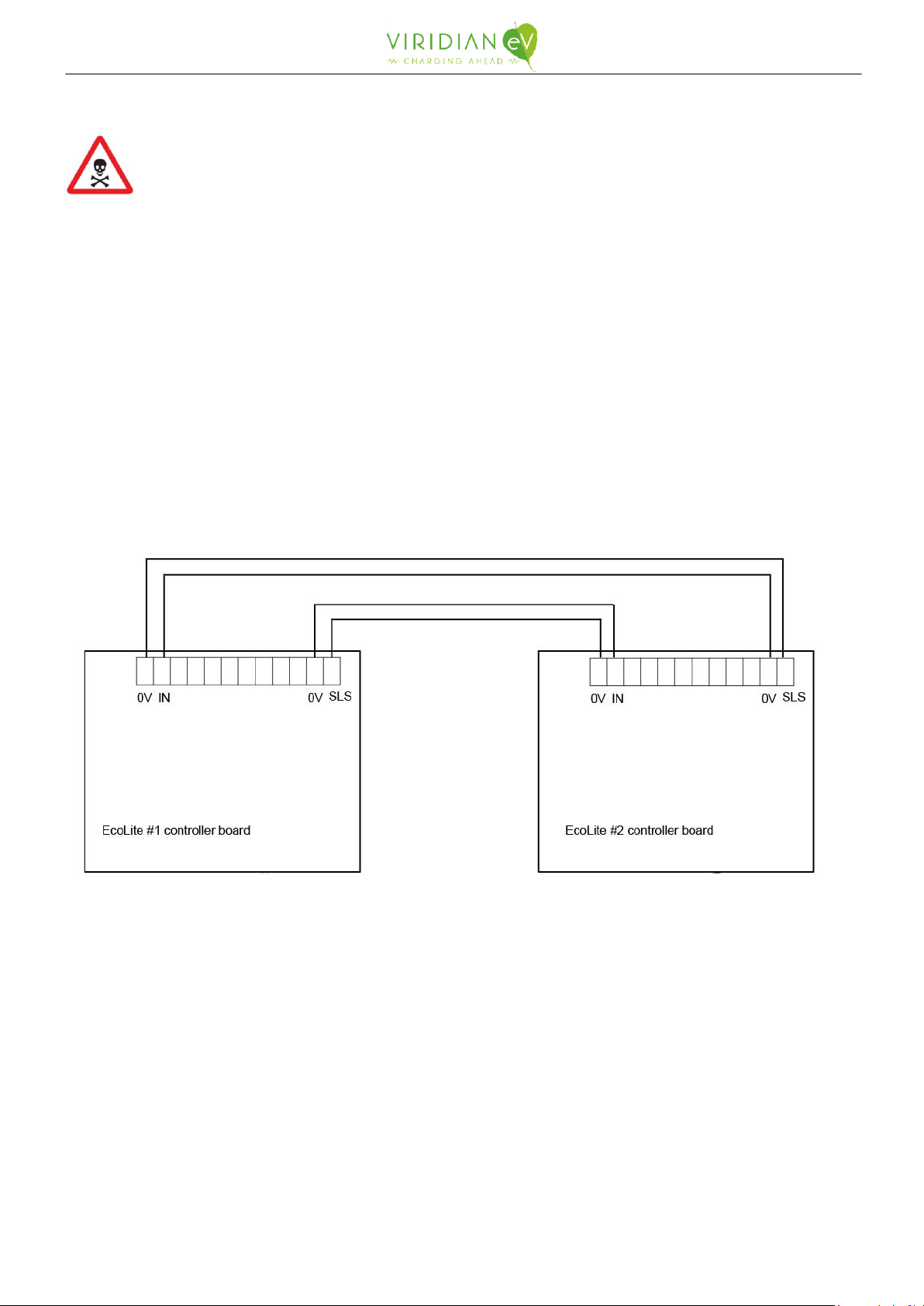
Using Simple Load Share (SLS)
WARNING
This is not user configurable and must be set by a qualified electrician / installer. Any changes to the
maximum advertised current of the unit need to be done with consideration for other components and
infrastructure. Misuse of this could cause fire and injury.
Two EcoLites installed near each other can make use of Simple Load Share functionality. This integrated
functionality, once enabled, will allow two EcoLites to safely share one supply. When two EVs are
plugged in, the SLS system will engage and share the total available power (nominally half to each to
vehicle). If one EV is plugged in or charging then all power will be made available again.
Procedure
1. Ensure power to the unit is off has been isolated
2. Remove the enclosure lid
3. Connect the correct terminals together on each EcoLite as per connection diagram below
4. Carefully adjust the settings of DIP switch (Fig. C –8) using the table on Annex 1 as reference
5. Replace enclosure lid and restore power the unit
EcoLite #1 'SLS' & '0V' connects to EcoLite #2 'IN' & '0V'
EcoLite #2 'SLS' & '0V' connects to EcoLite #1 'IN' & '0V'
See table on Annex 1 for configuration of the SLS mode and maximum current. The Current / SLS
configuration DIP-switche (Fig. C –8) on both EcoLites must be set to the same, which will be the
maximum available current for the whole system.
By default the units are configured for 32A with SLS enabled.
We advise that a suitably rated MCB equalling the maximum available for the system be placed upstream
of the two EcoLites. This will protect the system & infrastructure in the event of an accidental miss-
configured DIP switch.

Iss 1 - May 2018 Page 8 of 14
Viridian EV is a trading name of EcoHarmony Ltd.
Service and maintenance
DANGER
Contact with live components can result in serious injuries. Isolate the power before commencing any
work and removing the enclosure lid
THERE ARE NO USER SERVICEABLE COMPONENTS WITHIN THIS CHARGE POINT.
Please note that even though every care has been taken to select high quality components, in the
event that you should experience problems with this unit, servicing should only be carried out by a
suitably qualified individual. As the charge point is mostly modular in design, often the affected
component can be replaced on site with the defective part being sent back to the manufacture for
analysis.
Procedure
Isolate all power to the charge point.
Disconnect the wiring from the affected component
If it’s a DIN rail mounted component, remove the device by pulling the locking slider and
swivel the device away from the DIN rail
If it is the controller board, remove the 4 mounting screws and carefully remove board
observing ESD handling procedures
Install a new device by either placing it over the DIN rail and firmly pushing it down or
screwing a new board into place (ensure board mains cover is re-fitted)
Reconnect all wiring and check that all connections are tightened to the required torque
(see Annex 4 or manufacturer’s technical data).
Re-establish the power supply to the charge point.
Cleaning
It is recommended that cleaning of the outside of the charge point should be performed using a damp
cloth and a mild cleaning solution, if necessary.
CAUTION
Cleaning the charge point with a high-pressure water hose is not permitted and could cause water build
up within the charge point.
The charge point should not be opened and cleaned internally.

Iss 1 - May 2018 Page 9 of 14
Viridian EV is a trading name of EcoHarmony Ltd.
-- -- THIS PAGE INTENTIONALLY LEFT BLANK-- --

Iss 1 - May 2018 Page 10 of 14
Viridian EV is a trading name of EcoHarmony Ltd.
Annex 1: EcoLite Current & SLS Configuration
WARNING
This is not user configurable and must be set by a qualified electrician / installer. Any changes to the
maximum advertised current of the unit need to be done with consideration for other components and
infrastructure. Misuse of this could cause fire and injury.
When using SLS functionality, the current / SLS configuration DIP-switches (Fig. C –8) on both EcoLites
must be set to the same, which will be the maximum available current for the whole system.
Column1
4
3
2
1
Current
Level
SLS
Compatible
0
OFF
OFF
OFF
OFF
32
Y
1
OFF
OFF
OFF
ON
6
N
2
OFF
OFF
ON
OFF
9
N
3
OFF
OFF
ON
ON
10
N
4
OFF
ON
OFF
OFF
11
N
5
OFF
ON
OFF
ON
14
Y
6
OFF
ON
ON
OFF
15
Y
7
OFF
ON
ON
ON
16
Y
8
ON
OFF
OFF
OFF
18
Y
9
ON
OFF
OFF
ON
20
Y
10
ON
OFF
ON
OFF
22
Y
11
ON
OFF
ON
ON
24
Y
12
ON
ON
OFF
OFF
25
Y
13
ON
ON
OFF
ON
28
Y
14
ON
ON
ON
OFF
30
Y
15
ON
ON
ON
ON
Demo Mode
N/A

Iss 1 - May 2018 Page 11 of 14
Viridian EV is a trading name of EcoHarmony Ltd.
Annex 2: EcoLite LED Brightness Configuration
WARNING
This is not user configurable and must be set by a qualified electrician / installer as it requires isolating
power to the unit and removing the enclosure lid.
Should there be a requirement to change the brightness of the status indicator LEDs, or to turn off the
halo completely, then set the brightness configuration DIP switch (Fig. C –7) as per the settings in the
below table.
1
2
Brightness
OFF
OFF
Max
OFF
ON
Medium
ON
OFF
Low
ON
ON
Halo Off

Iss 1 - May 2018 Page 12 of 14
Viridian EV is a trading name of EcoHarmony Ltd.
Annex 3: EcoLite dimensions and mounting information
The drawing below indicates dimensions of the EcoLite charge point and the position of the mounting
holes to aid in mounting the unit to a wall or post. Note; drawing is not to scale.
A 1:1 scale version that can be used as a drill template is available online and from your distributor but
will need to be printed on A3 to be ‘actual size’.

Iss 1 - May 2018 Page 13 of 14
Viridian EV is a trading name of EcoHarmony Ltd.
Annex 4: Recommended torque settings for terminals & fixings
The below terminal torque settings apply to the switchgear specified for assembly at the time of writing
and is correct as per the manufacturers specifications. It is always reccomended to check the
manufacturer’s specifications if fitting any other switchgear than that supplied by Viridian EV.
M5 terminals on all switchgear: 2NM
M3 terminals on contactor (A1 + A2): 0.8NM
4 x M3 fixings for PCB: 0.8NM

Iss 1 - May 2018 Page 14 of 14
Viridian EV is a trading name of EcoHarmony Ltd.
Viridian EV
42 Elliott Road,
Love lane Industrial Estate,
Cirencester,
Gloucestershire
GL7 1YS
Tel: +44 (0)177 230 7172
Web: www.viridianev.co.uk
Other manuals for EcoLite Basic
1
Table of contents
Other Viridian EV Batteries Charger manuals


