Viridian CSI1000 User manual

V1.0-2023-02-30
Quick Installation Guide
Grid-Tied PV Inverter
(CSI1000|CSI1500 |CSI2000 |CSI2500 |CSI3000)

1
General Disclaimer
Safety Disclaimer
Warning
• The information in this quick installation guide is subject to change due to product updates
or other reasons. This guide cannot replace the product labels or the safety precautions in
the user manual unless otherwise specied. All descriptions here are for guidance only.
• Before installations, read through the quick installation guide. For additional information,
please see the user manual.
• All operations should be performed by trained and knowledgeable technicians who are
familiar with local standards and safety regulations.
• Check the deliverables for correct model, complete contents, and intact appearance. Contact
the manufacturer if any damage is found or any component is missing.
• Use insulating tools and wear personal protective equipment when operating the equipment
to ensure personal safety. Wear anti-static gloves, clothes, and wrist strip when touching
electronic components to protect the inverter from damage. The manufacturer shall not be
liable for any damage caused by static electricity.
• Strictly follow the installation, operation, and conguration instructions in this guide and user
manual. The manufacturer shall not be liable for equipment damage or personal injury if you
do not follow the instructions.
DC Side:
1. Ensure the component frames and the bracket system are securely grounded.
2. Connect the DC cables using the delivered PV connectors. The manufacturer shall not be
liable for equipment damage if other connectors are used.
3. Ensure the DC cables are connected tightly, securely, and correctly. Inappropriate wiring
may cause poor contacts or high impedances, and damage the inverter.
4. Measure the DC cable using the multimeter to avoid reverse polarity connection. Also, the
voltage should be under the max DC input voltage. The manufacturer shall not be liable for
the damage caused by reverse connection and extremely high voltage.
5. The PV modules used with the inverter must have an IEC61730 class A rating.
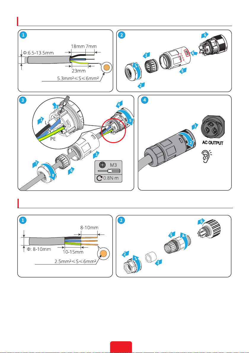
AC Side:
1. The voltage and frequency at the connecting point should meet the on-grid requirements.
2. Additional protective devices like circuit breakers or fuses are recommended on the AC
side. Specication of the protective device should be at least 1.25 times the rated AC output
rated current.
3. PE cable of the inverter must be connected rmly. The resistance between the neutral wire
and the earth cable is less than 10Ω.
4. You are recommended to use copper cables as AC output cables. If you prefer aluminum
cables, remember to use copper to aluminum adapter terminals.
EN
01 Safety Precautions

2
Product :
1. Do not apply mechanical load to the terminals, otherwise the terminals can be damaged.
2. All labels and warning marks should be visible after the installation. Do not scrawl, damage,
or cover any label on the device.
3. Unauthorized dismantling or modication may damage the equipment, the damage is not
covered under the warranty.
4. Install the inverter away from high magnetic eld to avoid electromagnetic interference.
If there is any radio or wireless communication equipment below 30MHz near the inverter,
you have to:
• Install the inverter at least 30m far away from the wireless equipment.
• Add a low pass EMI lter or a multi winding ferrite core to the DC input cable or AC
output cable of the inverter.
5. Warning labels on the inverter are as follows.
HIGH VOLTAGE HAZARD.
Disconnect all incoming power
and turn o the product before
working on it.
Delayed discharge. Wait 5 minutes
after power o until the components
are completely discharged.
Read through the guide before
working on this device.
Potential risks exist. Wear proper
PPE before any operations.
High-temperature hazard. Do
not touch the product under
operation to avoid being burnt.
Grounding point. Indicates the
position for connecting the PE cable.
CE marking Do not dispose of the inverter
as household waste.Discard the
product in compliance with local
laws and regulations, or send it back
to the manufacturer.
5min
Check before Power-on
No. Check Item
1The product is rmly installed at a clean place that is well-ventilated and easy-to-
operate.
2The PE, DC input, AC output, and communication cables are connected correctly and
securely.
3 Cable ties are intact, routed properly and evenly.
4 Unused ports and terminals are sealed.
5The voltage and frequency at the connection point meet the inverter grid connection
requirements.

3
Indicator Status Description
ON = WiFi is connected/active.
BLINK 1 = WiFi system is resetting.
BLINK 2 = WiFi not connect to the router.
BLINK 4 = WiFi server problem.
BLINK = RS485 is connected.
OFF = WiFi is not active.
ON = The inverter is feeding power.
OFF = The inverter is not feeding power at the moment.
ON = A fault has occurred.
OFF = No fault.
Faulty
Operating
Power
LED Indicators

4
Parts
1. DC Switch(optional) 2. PV Input Terminal 3.
WiFi/LAN/4G
Communication Module
Port
4.
DRED/CT/
Remote Shutdown
Communication Cable
Port(optional)
5. AC Output Terminal 6. PE Terminal
7. Indicator 8. LCD(optional) 9. Button(optional)
10. Heat Sink 11. Mounting Plate
02 Product Introduction

5
Dimensions
x 1
x 1
x 1 x 1
or
or
x 1
x N x N
x 1
x 1
x 3
x 1
N = Quantity depends on the inverter model.
Inverter Installation
03

6
Space Requirements
Children No Touch

7
Installing the Inverter
Angle Requirements

8
PE Cable
Copper,
AC Cable
Click
AC-1
or
AC-2
Electrical Connection
04

9
AC-1 Connector
Click
AC-2 Connector
Copper,
Copper,

10
DC Cable
DEVALAN Series MC4 Series
Click
Click

11
CSI2500, CSI3000: ≤600V
Others: ≤500V
DEVALAN
MC4
Click
Click

12
CSI2500, CSI3000: ≤600V
Others: ≤500V
RS485 Communication Cable
Click
Click
No.
Function
1N/A
2N/A
3RS485-
4N/A
5N/A
6RS485+
7RS485-
8 RS485+

13
CT Communication Cable
No.
Function
1CT-
2CT+

14
For Europe only: Remote Shutdown Communication Cable
No.
Function
4Content +
5 Content -

15
WARNING
Keep the Remote Shutdown Terminal installed anyway.

16
14
13
Power ON Power OFF
Turn on Turn o
DC Isolator
(Optional)
32
AC Breaker
Inverter
PV Grid
Power On and O
05

17
Commissioning via WE Mate APP
Commissioning via LCD
Set country code
Select
Country/Region Country code 1
Country code 2
Normal
Pac=2595.5W
Commissioning
06
Monitoring via Solar Portal App
play
App Store
WE Mate APP
WE Mate
Solar Portal
Solar Portal APP

Viridian Solar Ltd
E-mail: info@viridiansolar.co.uk
www.viridiansolar.co.uk 340-00XXX -XX
This manual suits for next models
4
Table of contents
Other Viridian Inverter manuals