Viridian CSI1500 User manual
User Manual
V1.0-2023-02-30
Grid-Tied PV Inverter
(CSI1000|CSI1500 |CSI2000 |CSI2500 |CSI3000)

I
The information in this user manual is subject to change due to product updates or other
reasons. This guide cannot replace the product labels or the safety precautions in the user
manual unless otherwise specied. All descriptions here are for guidance only.
and other trademarks are trademarks of
Viridian Solar Ltd
. All other
trademarks or registered trademarks mentioned in this manual are owned by
Viridian Solar Ltd
.
NOTICE
Trademarks

II
CONTENT
1 About This Manual .................................................................1
1.1 Applicable Model..........................................................................................1
1.2 Target Audience............................................................................................1
1.3 Symbol Denition.........................................................................................2
1.4 Updates .........................................................................................................2
2 IMPORTANT SAFETY INSTRUCTIONS ....................................3
2.1 General Safety ..............................................................................................3
2.2 DC Side ..........................................................................................................3
2.3 AC Side...........................................................................................................4
2.4 Inverter Installation .....................................................................................4
2.5 Personal Requirements...............................................................................5
3 Product Introduction.............................................................6
3.1 Application Scenarios ..................................................................................6
3.2 Circuit Diagram.............................................................................................6
3.3 Supported Grid Types..................................................................................6
3.4 Appearance...................................................................................................7
3.4.1 Parts........................................................................................................................7
3.4.2 Dimensions ............................................................................................................8
3.4.3 Indicators ...............................................................................................................8
3.4.4 Nameplate .............................................................................................................9
4 Check and Storage ...............................................................10
4.1 Check Before Receiving.............................................................................10
4.2 Deliverables ................................................................................................10
4.3 Storage ........................................................................................................11
5 Installation ...........................................................................12
5.1 Installation Requirements.........................................................................12
5.2 Inverter Installation ...................................................................................15
5.2.1 Moving the Inverter............................................................................................15
6 Electrical Connection...........................................................16

III
6.1 Safety Precaution .......................................................................................16
6.2 Connecting the PE Cable ...........................................................................17
6.3 Connecting the PV Input Cable ................................................................17
6.4 Connecting the AC Output Cable .............................................................20
6.5 Communication ..........................................................................................24
6.5.1 Communication Network Introduction............................................................24
6.5.2 Connecting the Communication Cable (optional)...........................................24
6.5.3 Connecting the RS485 Cable ............................................................................25
6.5.4 Connecting the Remote Shutdown Cable ......................................................26
6.5.5 Connecting the CT Cable ..................................................................................27
6.5.6 Connecting the DRED Cable ............................................................................28
7 Equipment Commissioning.................................................29
7.1 Check Before Power ON ............................................................................29
7.2 Power On.....................................................................................................29
8 System Commissioning .......................................................30
8.1 Indicators and Buttons..............................................................................30
8.2 Setting Inverter Parameters via LCD .......................................................30
8.2.1 Inverter Parameter Introduction ......................................................................32
8.3 Upgrading the Firmware Via USB Flash Disk ..........................................34
8.4 Setting Inverter Parameters via WE Mate App.......................................34
8.5 Monitoring via Solar Portal ......................................................................34
9 Maintenance.........................................................................35
9.1 Power O the Inverter...............................................................................35
9.2 Removing the Inverter...............................................................................35
9.3 Disposing of the Inverter ..........................................................................35
9.4 Troubleshooting .........................................................................................35
9.5 Routine Maintenance.................................................................................38
10 Technical Parameters ........................................................39

1
This manual applies to the listed inverters below:
Model Nominal Output Power Nominal Output Voltage
CSI1000 1000W
230VCSI1500 1500W
CSI2000 2000W
CSI2500 2500W
220/230V
CSI3000 3000W
1 About This Manual
This manual describes the product information, installation, electrical connection, commissioning,
troubleshooting, and maintenance. Read through this manual before installing and operating the
product. All the installers and users have to be familiar with the product features, functions, and
safety precautions. This manual is subject to update without notice.
1.1 Applicable Model
1.2 Target Audience
This manual applies to trained and knowledgeable technical professionals. The technical
personnel has to be familiar with the product, local standards, and electric systems.

2
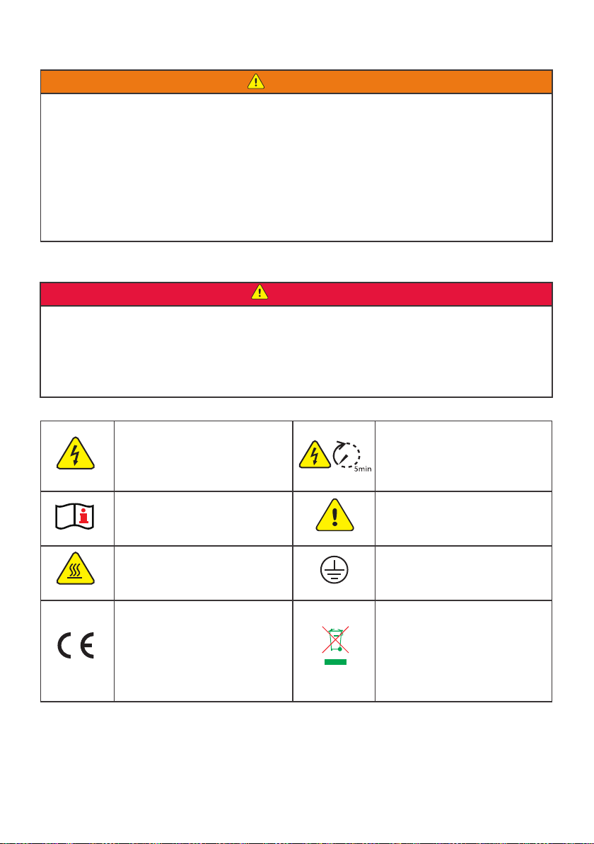
1.3 Symbol Denition
1.4 Updates
The latest document contains all the updates made in earlier issues.
V1.0 2023-02-30
• First Issue
Dierent levels of warning messages in this manual are dened as follows:
DANGER
Indicates a high-level hazard that, if not avoided, will result in death or serious injury.
WARNING
Indicates a medium-level hazard that, if not avoided, could result in death or serious injury.
CAUTION
Indicates a low-level hazard that, if not avoided, could result in minor or moderate injury.
NOTICE
Highlight and supplement the texts. Or some skills and methods to solve product-related
problems to save time.

3
SAVE THESE INSTRUCTIONS
Please strictly follow these safety instructions in the user manual during the operation.
2 IMPORTANT SAFETY INSTRUCTIONS
NOTICE
The inverters are designed and tested strictly complies with related safety rules. Read and
follow all the safety instructions and cautions before any operations. Improper operation might
cause personal injury or property damage as the inverters are electrical equipment.
2.1 General Safety
NOTICE
• The information in this user manual is subject to change due to product updates or other
reasons. This guide cannot replace the product labels or the safety precautions in the user
manual unless otherwise specied. All descriptions here are for guidance only.
• Before installations, read through the quick installation guide. For additional information,
please see the user manual.
• All installations should be performed by trained and knowledgeable technicians who are
familiar with local standards and safety regulations.
• Use insulating tools and wear personal protective equipment when operating the
equipment to ensure personal safety. Wear anti-static gloves, cloths, and wrist strips when
touching electron devices to protect the inverter from damage.
• Strictly follow the installation, operation, and conguration instructions in this manual. The
manufacturer shall not be liable for equipment damage or personal injury if you do not
follow the instructions.
DANGER
Connect the DC cables using the delivered PV connectors. The manufacturer shall not be liable
for the equipment damage if other connectors or terminals are used.
WARNING
• Ensure the component frames and the bracket system are securely grounded.
• Ensure the DC cables are connected tightly, securely and correctly.
• Measure the DC cable using the multimeter to avoid reverse polarity connection. Also, the
voltage should be under the permissible range.
• Do not connect the same PV to multiple inverters. Otherwise, the inverters may be
damaged.
• The PV modules used with the inverter must have an IEC61730 class A rating.
2.2 DC Side
4
DANGER High voltage hazard.
Disconnect all incoming power
and turn o the product before
working on it.
Delayed discharge. Wait
5 minutes after power o
until the components are
completely discharged.
Read through the user manual
before working on this device.
Potential risks exist. Wear
proper PPE before any
operations.
High-temperature hazard. Do
not touch the product under
operation to avoid being burnt.
Grounding point.
CE Mark Do not dispose of the inverter
as household waste. Discard
the product in compliance with
local laws and regulations,
or send it back to the
manufacturer.
WARNING
• The voltage and frequency at the connection point meet the inverter grid connection
requirements
• Additional protective devices like circuit breakers or fuses are recommended on the AC
side. Specication of the protective device should be at least 1.25 times the rated AC output
rated current.
• Make sure that all the groundings are tightly connected.
• You are recommended to use copper cables as AC output cables. Contact the manufacturer
if you want to use other cables.
2.3 AC Side
2.4 Inverter Installation
DANGER
• Do not apply mechanical load to the terminals, otherwise the terminals can be damaged.
• All labels and warning marks should be visible after the installation. Do not scrawl,
damage, or cover any label on the device.
• Testing to AS/NZS 4777.2:2020 for multiple inverter combinations has not been conducted.
• Warning labels on the inverter are as follows.

5
2.5 Personal Requirements
NOTICE
• Personnel who install or maintain the equipment must be strictly trained, learn about
safety precautions and correct operations.
• Only qualied professionals or trained personnel are allowed to install, operate, maintain,
and replace the equipment or parts.
6
3 Product Introduction
3.1 Application Scenarios
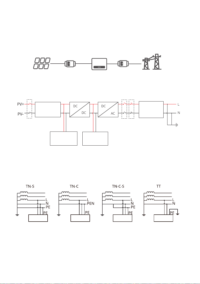
3.2 Circuit Diagram
3.3 Supported Grid Types
The inverter is a single-phase PV string grid-tied inverter, which converts the DC power
generated by the PV module into AC power for loads or the grid. The intended use of the
inverter is as follows:
DC Switch
Mains bridge relay
Mains relay
I/P Filter &
surge Voltage
protection
PV insulation
check Power Supply
EMI Filter &
surge Voltage
protection
Inverter Inverter Inverter Inverter
For the grid type with neutral wire, the N to ground voltage must be less than 10V.
PV String Inverter Circuit
Breaker
Circuit Breaker
(optional) Utility
Grid
This manual suits for next models
4
Table of contents
Other Viridian Inverter manuals


Popular Inverter manuals by other brands


BARRON
BARRON EXITRONIX Tucson Micro Series installation instructions

Baumer
Baumer HUBNER TDP 0,2 Series Mounting and operating instructions

electroil
electroil ITTPD11W-RS-BC Operation and Maintenance Handbook

Silicon Solar
Silicon Solar TPS555-1230 instruction manual

Mission Critical
Mission Critical Xantrex Freedom SW-RVC owner's guide

HP
HP 3312A Operating and service manual


