Visionis VIS-440 Series User manual
Electric Automatic Door Opener
VIS-440 Series
Installation Manual
www.visionistech.com

Table Content
1 Technical Parameters
2 Components
3 Installation Steps
3.1
Installation of bottomplate
3.2
Installation of bottom plate
3.3
Installation of pull bar
3.4
Installation of pull bar
3.5 Installation of push bar
1
2
4-12
4
5
6-7
8
9
3.6 Installation of push bar 10
3.7 Finished installation
3.8 Mechanism and cover installation
4 Wired diagram
4.1
Terminal details of controller
4.2
Data setting
4.3
Connection of commonly used and special function
11
12
13-15
13
13
14-15
5 Remote Functions 16
6 LED display feedback 17
7 Trouble shooting 17

1. Technical Parameters
Dimensions (LWH)
515.62*78.74*114.3mm (20.3*3.1*4.5 Inches)
Weight
17.7lbs
Ambient temperature
-20°C~ +50°C (-4°F~ 122°F)
Operation voltage
AC 100V -127V
Power supply external consumption
24V DC (±10%), 3A
Door opening angle
Max 120°
Opening speed
45°/S
Closing speed
45°/S
Hold-open time
0-60S
Protection class
IP42 Indoor use only
mm=Door width
kg=Door weight
Suitable range
Limit range
mm
2000
1500
1000
80 120 160
100 140
180
kg
200
1
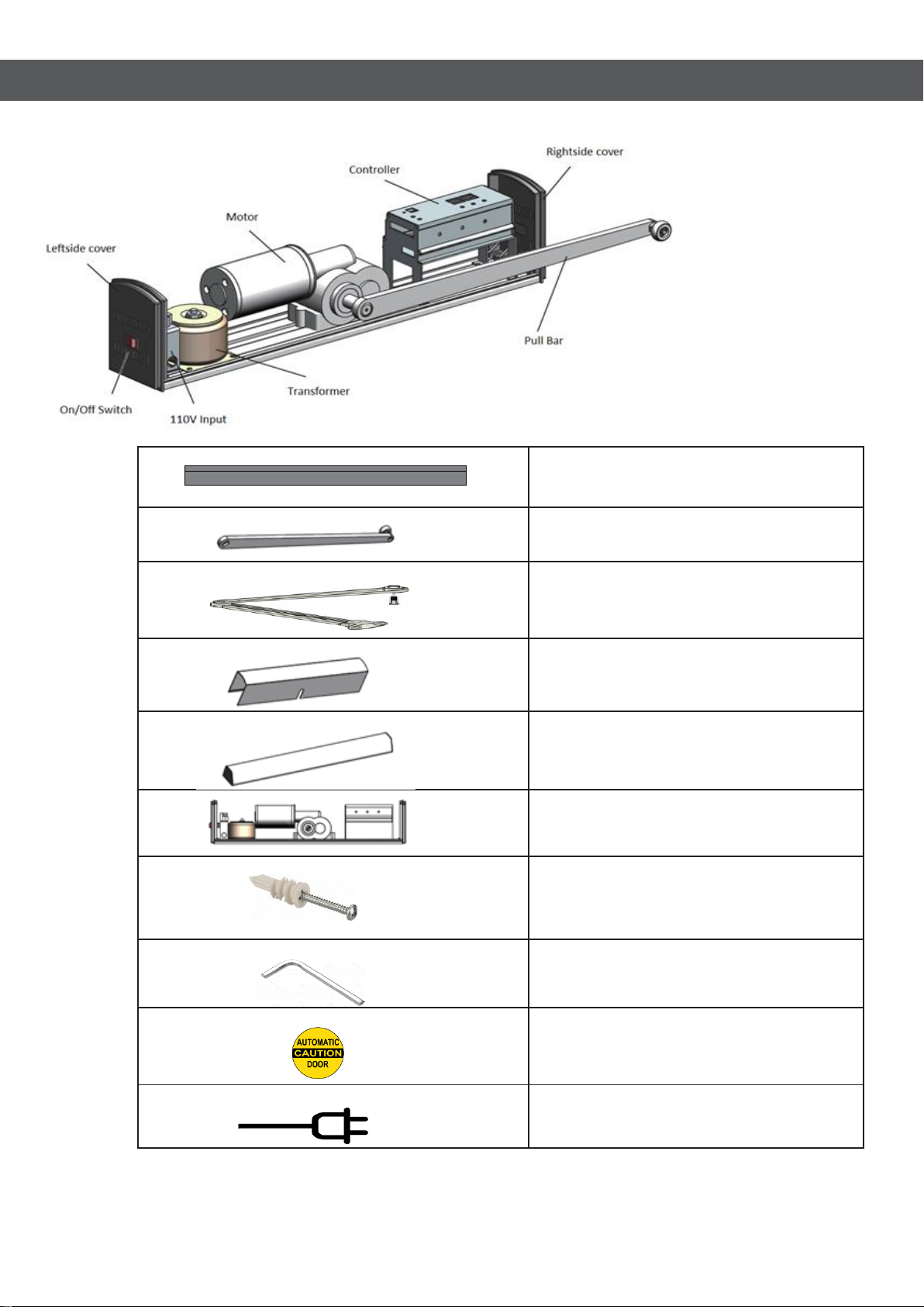
2. Components
Bottom plate
Pull bar (inswing)
Push bar(outswing)
Cover
Pull guider
Mechanism
Installation Screws
Allen wrench
Door sticker
Power cord (AC)
Note: Only one type of door
bar comes with every kit
Connect the AC power cable
to 110V input
X 2
X 8
2

Safety devices should be in place and operational.
Have door adjusted as recommended in Owner’s
Manual if necessary.
Have door inspected at least annually by a certified
technician.
TYPICAL USED TOOLS
.
If you choose to use no locks or any other
type of locks that is not a door strike, this
latch must be remove for proper operation.
3
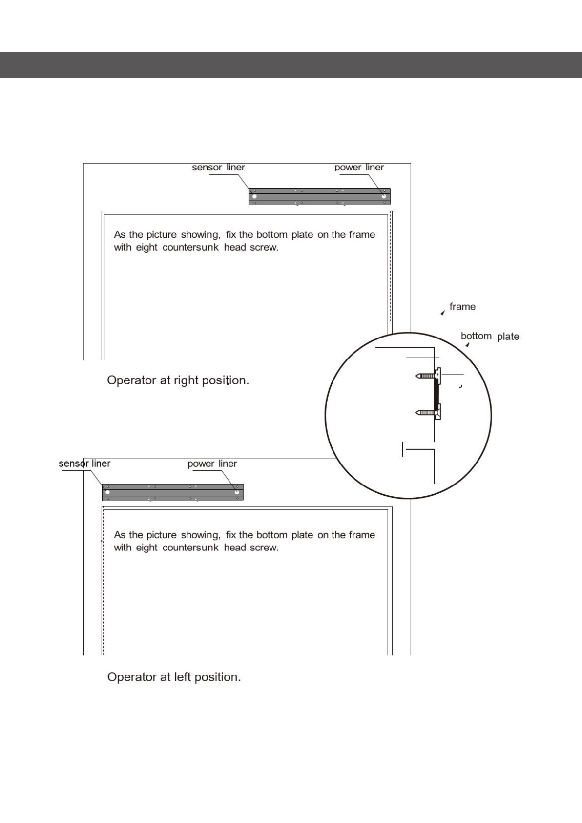
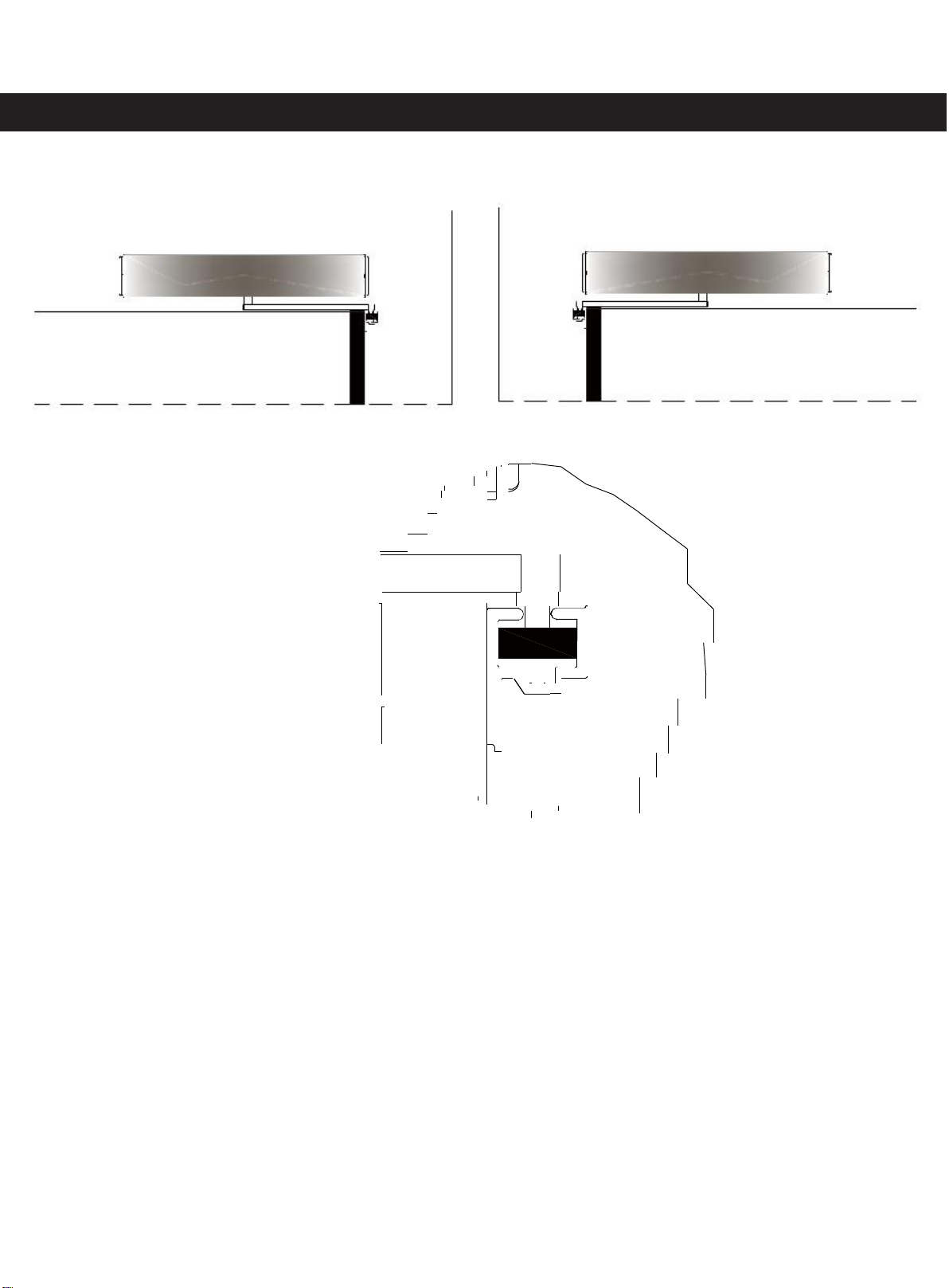
3.1
Installation of bottom plate
Pull bar type (inswing)
3. Installation Steps
30
4
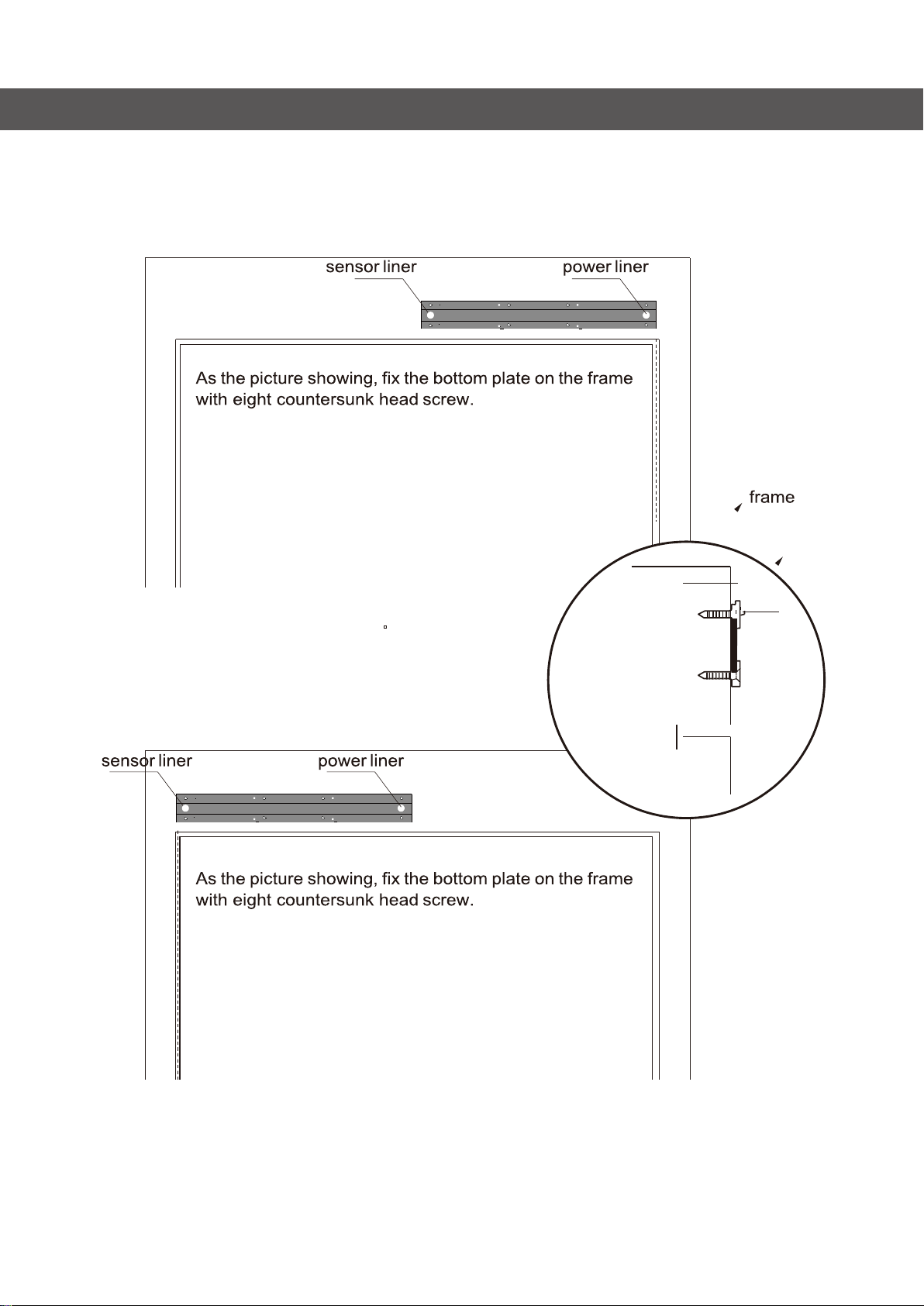
3.2
Installation of bottom plate
Push bar type (outswing)
plate
Operator at left position.
bottom
Operator at right position.
3. Installation Steps
5
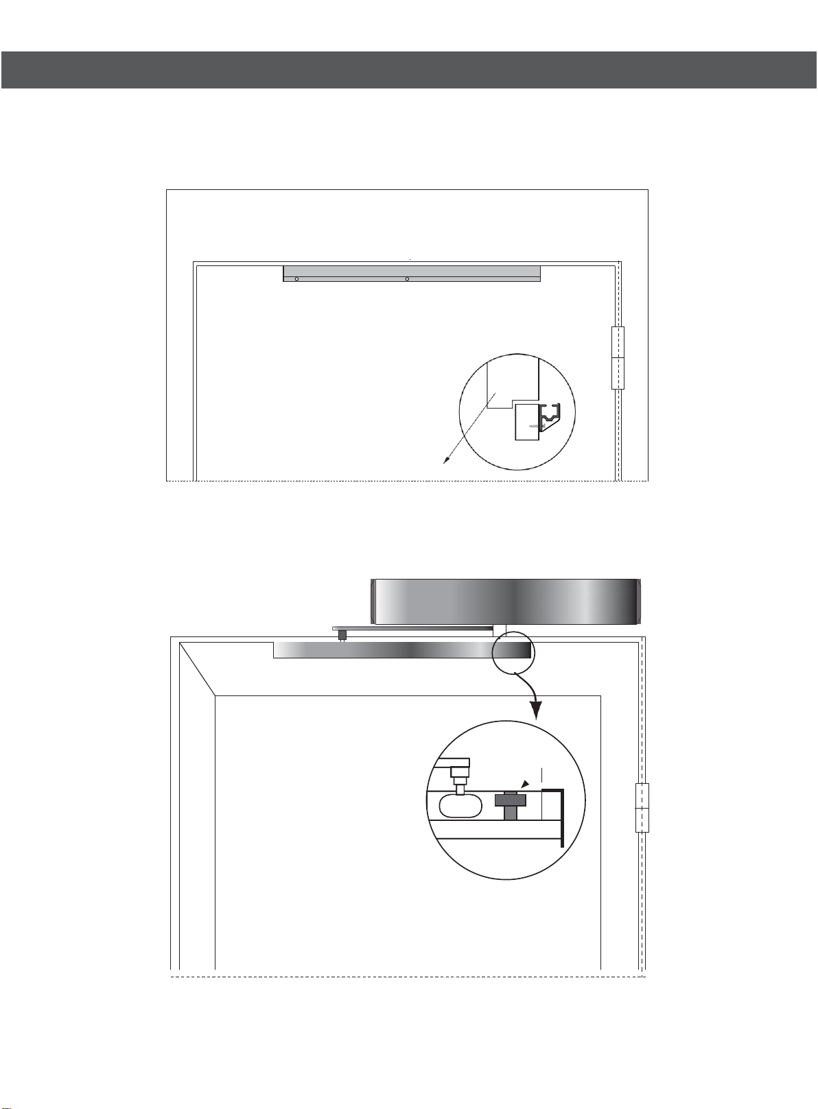
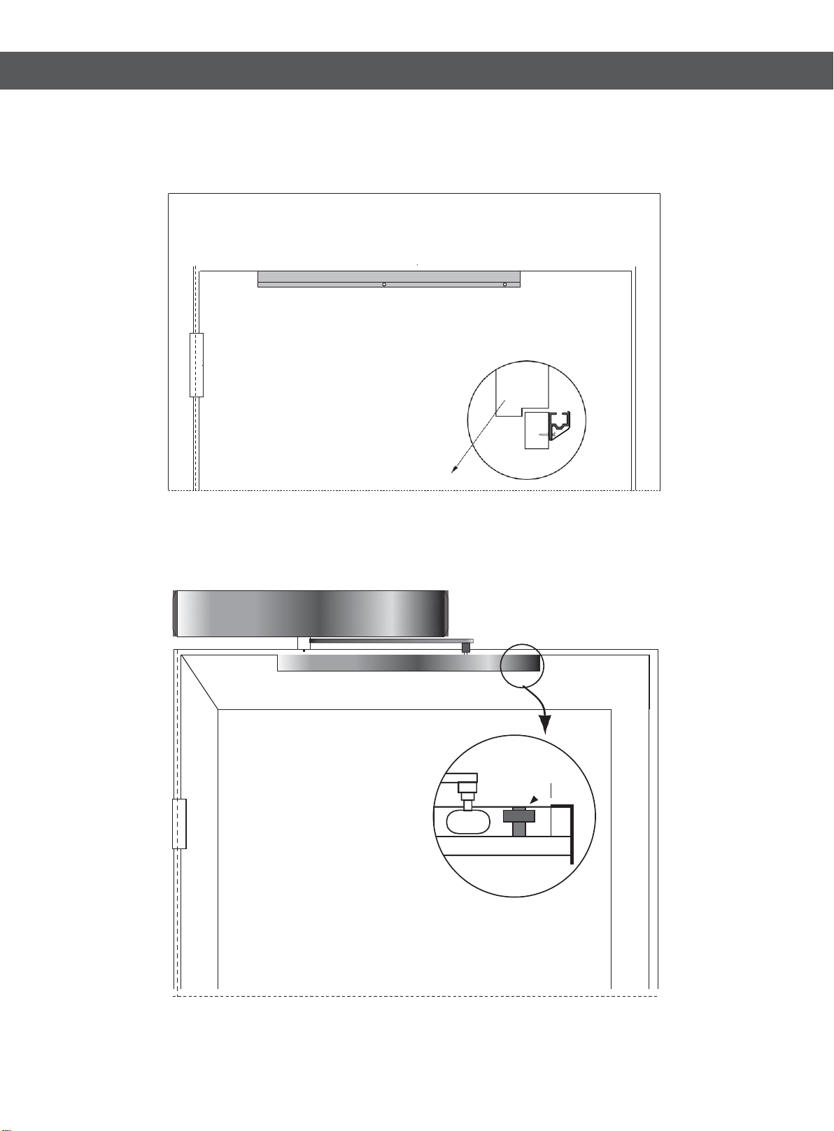
3.Installation Steps
3.3
Installation of pull bar guider (inswing)
Operator at Right position Operator at left position
1. Open the door to 90 degree before installation put the slider of pull bar into groove
2. Fix the pull bar installation plate according to the picture
3. Adjust the position of slider installation plate make sure the wheel is at the
Middle of groove as the picture shown
4. Keep the position of installation plate tighten the first screw at the axis of door
5. Close the door, repeat the step 3,tighten the second screw at another side
6. Manually open and close several times make sure the pull bar is working perfect,
If there is resistance please adjust the installation plate of pull bar again
7. Tighten the last screw
6
3.3 Installation of pull bar guider (Inswing Door)
A.
Right position
Door leaf
Fix the pull bar on door leaf with
3 pcs self-tapping screw.
Adjust the opening angle
by position stopper.
position stopper
3. Installation Steps
7
3.4 Installation of pull bar guider
B. Left position
Fix the pull bar on door leaf with
3 pcs self-tapping screw.
Door leaf
Adjust the opening angle
by position stopper.
position stopper
3. Installation Steps
8
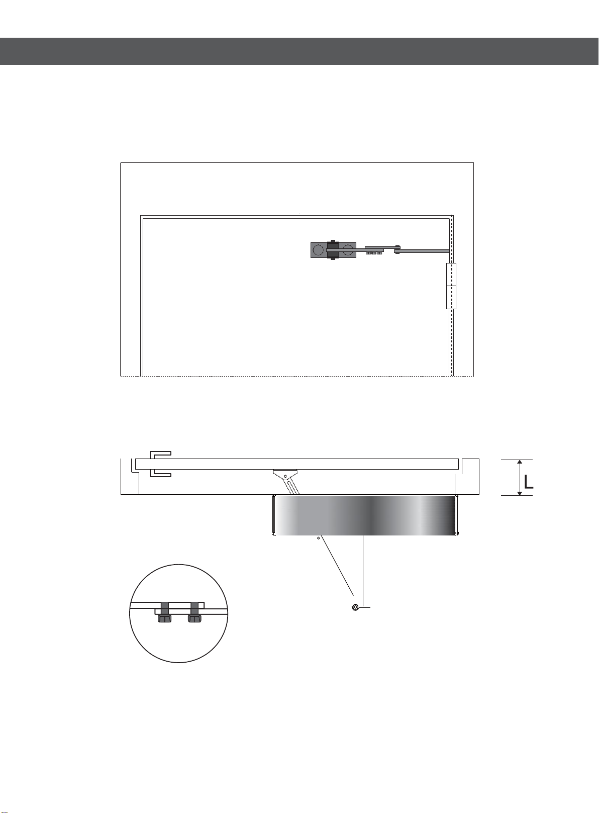
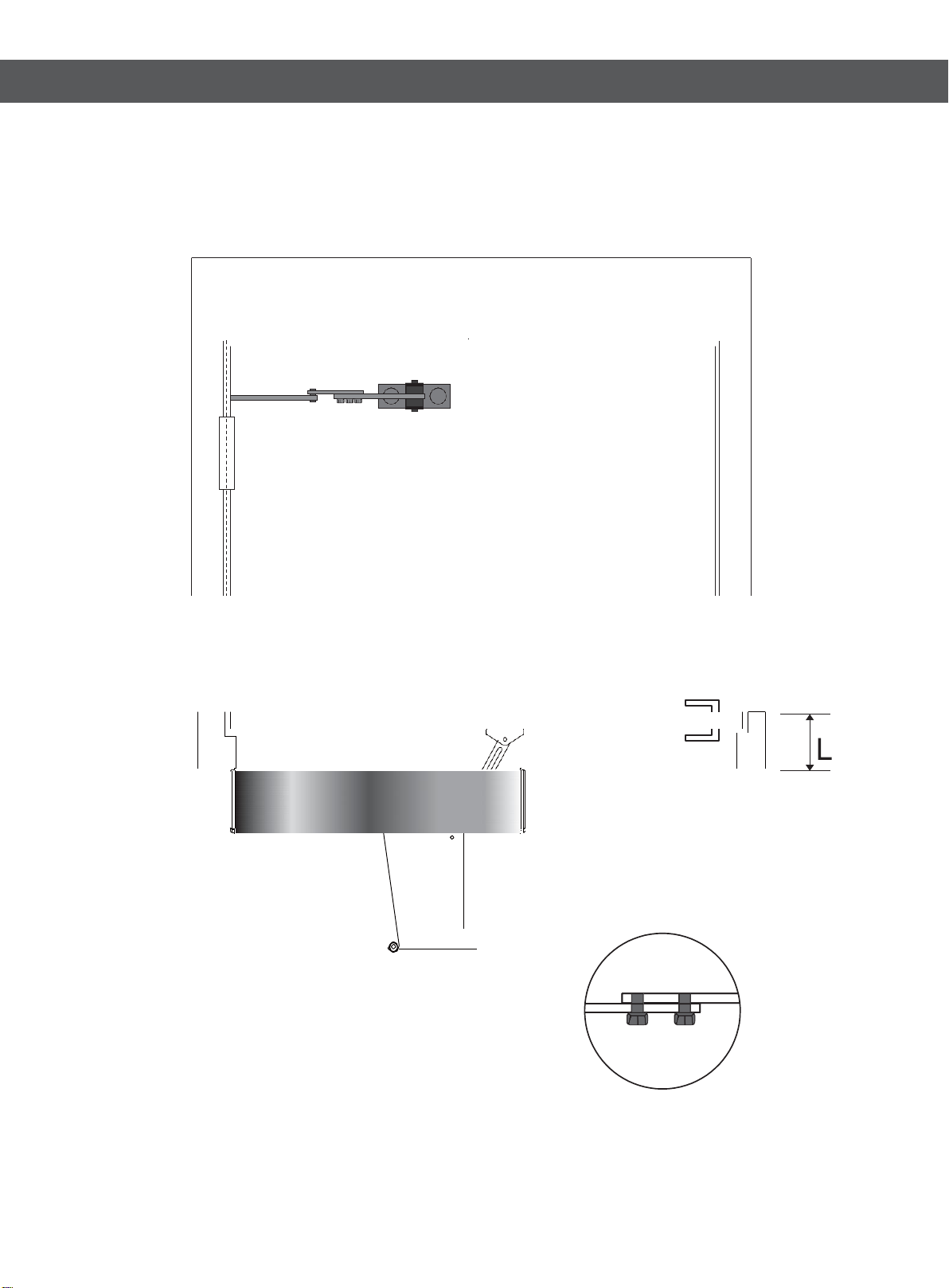
3.5 Installation of push bar (Outswing Door)
Adjust the push bar length by two screw according to the door frame’s depth(L).
3. Installation Steps
Fix the bottom of push bar to door leaf
9
3.6 Installation of push bar
B. Left position
Adjust the push bar length by two screw according to the door frame’s depth(L).
3. Installation Steps
Fix the bottom of push bar to door leaf
10

3.7 Finished installation
Pull bar: Door leaf open toward inside (same direction as operator)
Operator
Push bar: Door leaf open toward outside (opposite direction as operator)
operator
3. Installation Steps
11
Note: you may have to
install a door stopper if there
isn't one or a wall to stop the
door after opening.
3. Installation Steps
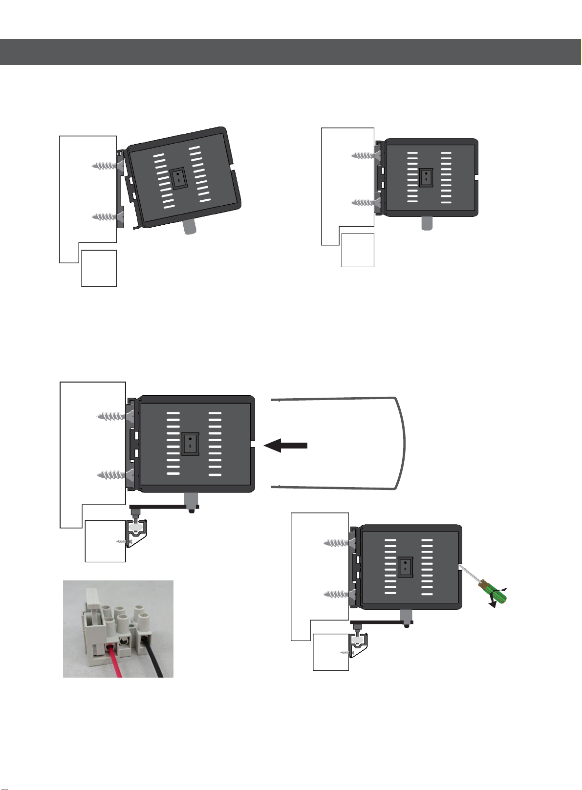
3.8 Mechanism installation
Note: First step is to remove the 8 mounting screws with Allen wrench. Separating the
Bottom plate from the mechanism, to be able to mount it on the wall
Hang the mechanism on the fixed base cover with screws.
Assemble and disassemble of the mechanism cover.
Note: Use a small
flathead screwdriver to
open the cover of the
mechanism
Note: Your power cord will have three cables, you will
only connect two. The green cable must be cut off and
the two remaining white and black cables go connected
into the terminals *Make sure the equipment switch is set
to the off position.
12
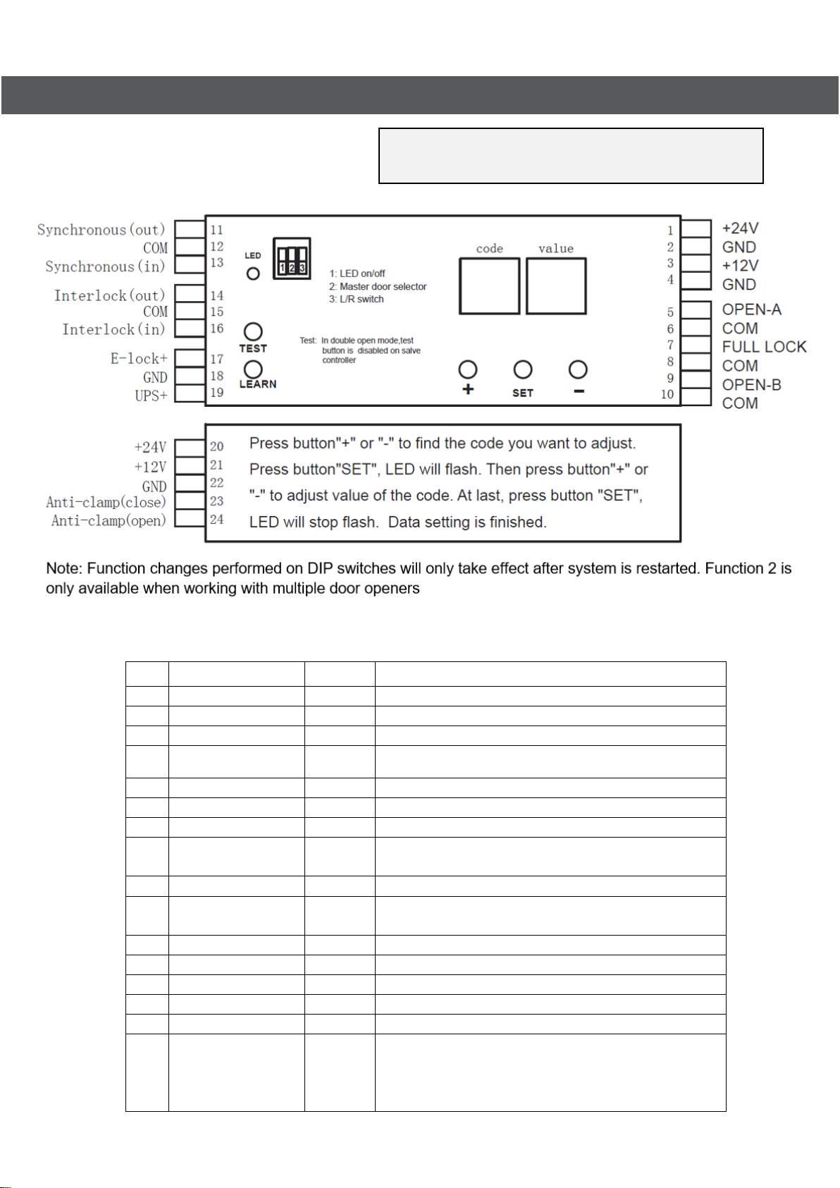
4. Wired Diagrams
4.1 Terminal details
4.2 Data setting
code
Setting range
Default
description
01
30-99
60
Opening speed(velocity to open)
02
30-99
50
Closing speed(velocity to close)
03
1-30
10
Delay opening speed (slowdown of door before full open status)
04
1-30
10
Delay closing speed (slowdown of door before full close
status)
05
10-50
30
Delay opening angle
06
10-50
30
Delay closing angle
07
0-60
2
Hold-open time 0-60s *time door is open after request
08
0,1,2...8
3
Starting delay time (0-4s,1=0.5s,when lock function
working)
09
0,1,2...8
2
Locking delay time(0-4s,1=0.5s)
10
0,1
1
Locking type (0 :lock by remote; 1 auto lock when
closed )
11
0,1
1
Push to open function(0:working,1 :not working)
12
1,2,3,4,5
3
Obstacle detection optimized for exterior(wind loads)
13
1,2,3,4,5
3
Auto-locking force
14
1,2,3,4,5
3
Anti-collision force
15
5-30
15
Auto-learning speed
16
0,1,2...10
2
Working interval between master and slave door (0-1s,
1=0.1s)
On master door. The setting is working when closing ;
On slave door. The setting is working when opening 。
13
NOTE: This product can be adjusted to work in either left or right
doors. To change the orientation of the motor Please use DIP
switch 3 located on the controller.

4. Wired Diagram
Inter-lock
24G Microwave sensor
14

4. Wired Diagram
Access Control Reader/Keypads (Stand-alone)
Access Control Panels (ETL & DLX Series, VIS-3013)
Wiring connection of electronic bolt lock
18. GND
17. Electronic lock+
Anti-clamp sensor when opening
24. Anti-clamp
22. GND
22.
GND
20. +24V
Anti-clamp sensor when closing
23.
Anti-clamp
22. GND
22. GND
20. +24V
+24V
GND
COM
NO
+24V
GND
COM
NO
15

5. Remote Functions
Operation of remote control
VIS-8016:
A:
Always open
B:
Closed
C:
Automatic open/close
D:
Fulllock
Add the remote :press the learning button on controller till the indicator turn from green to
red,then release the learning button and press A button on remote,the indicator turn from
red to green alternately 3 times,learning successful.
Delete the remote:press and hold the learning button after 5seconds,the indicator turn from
green to red and turn to green again press A button on the remote the he indicator turn
from red to green alternately 3 times all the remote memory is deleted (attention,
please hold he learning button when you delete the remote memory).
Wireless push button :Added and deleted wireless push button is same as remote.
Please check the DIP switch if it‘s same as the image shown during
setting process).
Notes:
1. Receiver has beenbuilt-in.
2. Lock grades:open A>full lock>open B.
It means when full lock function working, it lock accessories connected to open B, but
can't lock accessories connected to open A.
3. Exit only function:
Connect outside sensor or button to terminal “Open-B", connect inside sensor or button to
terminal "Open-A”. Then press "full lock" button on remote.
4.When double open, the transmitter should learn both operators together.
5.In double open mode accessories should connect to both controller (parallel connection).
A B
C D
ON
1 2 3 4
16

6. LED Display Feedback
Singleopening
Double opening
LED display
Details
LED display
Details
Dr11
No problem.
Dr12
Master door
Dr12 or Dr13
Terminal 11 and 13 are not
connected. (They should be
connected when single opening)
Dr13
Slave door
Er01
Over current protection for Controller.
Er01
Over current protection for Controller.
Er02
Motor has problems.
Er02
Motor has problems.
Er03
Synchronized wired problem.
Er04
Master door and slave door settings
problem.
7. Trouble Shooting
Symptoms
Causes
Items Checked
Remedies
Door opened or
closed
un-smoothly
Opening/closing speed is
set too slow
check the opening/closing
speed
speed up the opening/ closing
speed
learning speed is too fast
check the learning speed
slow down the learning speed
Too much resistance
check whether there
is something on the
door's working way
clear the obstacle away
Hit the door frame
suddenly when
closing, doorstop
suddenly when
opening
Buffer speed when
opening/closing is too fast
slow down the buffer speed
when opening/closing
Position stopper isloosen.
Fix the stopper.
Door doesn't work
No power
check the power
switch, connection
terminal from motor to
controller
connect the power
learning speed is tooslow
speed up the learning speed.
Door is locked
check whether the door is
locked.
un-lock the door
Obstacle in the pull bar's
guider.
check the pull bar guider
remove the obstacle
Resistance force is too
strong.
Power off, push the door
leaf. Make sure thedoor
work smoothly.
17
Other manuals for VIS-440 Series
1
Table of contents
Other Visionis Door Opening System manuals


Popular Door Opening System manuals by other brands

KALE
KALE KD-002/30-220 User & installation manual

Entrematic
Entrematic Ditec VALFM installation manual

Entrematic
Entrematic Ditec TOPSB installation manual

Entrematic
Entrematic Ditec VALLOKB installation manual

Keyautomation
Keyautomation LEV3281LT Instructions and warnings for installation and use

Synergy Hardware
Synergy Hardware S300 Series Fixing instructions


