Visionis VIS-8009 User manual

433MHz Outdoor Wireless Keypad / Reader Access
Control 500 Users Range of 165 Feet Delay and On/Off
Toggle Mode Battery Operated Standalone No Software
VIS-8009
User Manual
www.visionistech.com

INTRODUCTION
The keypad is wireless ABS keypad, which operated by 3units of AAA batteries, it can work as long as one
year (bases on 30 times/day).
SPECIFICATIONS
Operating Voltage
3 units of AAA batteries (Included)
Current
Idle Current
Working Current
≤10uA
≤80mA
Communication Frequency
244MHz
Communication Distance
50m Maximum (165 feet)
Relay Contact Load
2Amp Maximum
Environment
Operating Temperature
Operating Humidity
Outdoor Wireless Keypad
-40°C~60°C (-40°F~140°F)
0%~86%RH
Physical
Dimensions
Unit Weight
ABS Shell
L134 x W48 x D25(mm) –L5.27 x W1.89 x D0.98(inches)
150g
INSTALLATION
Method 1: Stick by 3M stickers
The device packed with 3M double-side Sticker, can easily stick the Wireless Keypad on Metal door, Glass
Door, Wooden Door, or Smooth Wall.
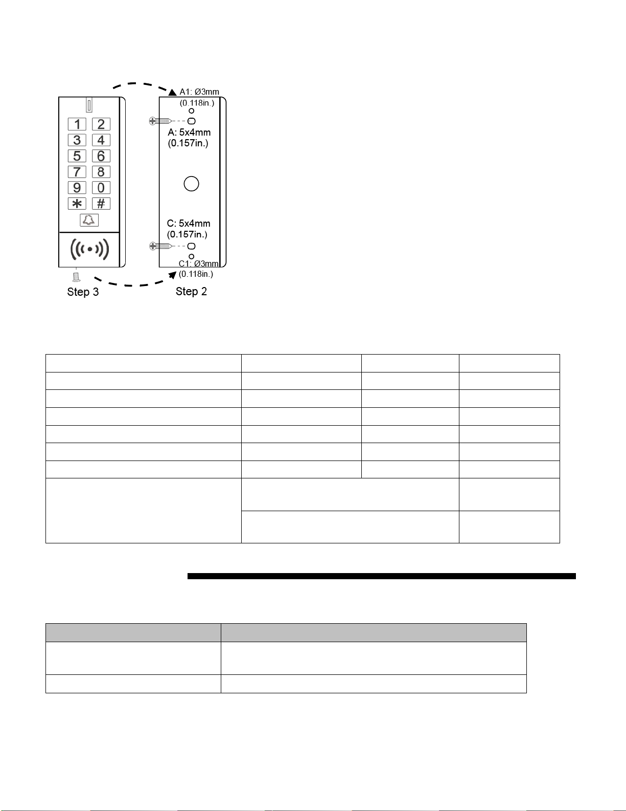
Method 2: Install by screws
Sound and Light Indication
Operation Status
Red LED
Green LED
Buzzer
Standby
-
-
-
Unlock the lock
-
ON for 3 seconds
-
Key press under Program Mode
-
-
One beep
Enter into Program Mode
Shines per 1.5 seconds
-
One long beep
Invalid PIN
-
-
3 beeps
Exit from the Program Mode
-
-
One beep
Low battery reminding
RED and GREEN alternately shines 2 times
(Wireless button)
-
ON (Wireless Keypad)
3 beeps when key
press
PROGRAMMING
Enter and Exit Program Mode
Programming Step
Keystroke Combination
1. Enter Program Mode
* (Master Code) #
(Factory default is 123456)
2. Exit
*

Set Master Code
Programming Step
Keystroke Combination
1. Enter Program Mode
* (Master Code) #
2. Update Master Code
0(New Master Code)#(Repeat New
Master Code)#
Master code is any 6 digits
3. Exit
*
Add User PIN(s)
User ID: 0~499
PIN length: 4~8 digits
Programming Step
Keystroke Combination
1. Enter Program Mode
* (Master Code) #
2. Add PIN
1 (User ID) # (PIN) # (Repeat PIN) #
The PINs can be added continuously
3. Exit
*
Add User Card(s)
User ID: 0~499
Card type: 125 KHz EM card
Programming Step
Keystroke Combination
1. Enter Program Mode
*(Master Code) #
2. Add Card: Using Auto ID
(Allows VIS-3200 to assign Card to next
available User ID number)
OR
2. Add Card: Select Specific ID
(Allows Master to define a specific User ID to
associate the card to)
1 (Read Card) #
The cards can be added continuously.
1 (User ID) # (Read Card) #
3. Exit
*
Add Visitor Users
There are 100 groups Visitor PIN / card available, the users can be specified up to 9 times of usage, after a
certain number of times, i.e. 5 times, the PIN/card become invalid automatically.
User ID: 00~099 (the leadind zero of the User ID means Visitor Users)
Programming Step
Keystroke Combination
1. Enter Program Mode
* (Master Code) #
2. Add visitor card
OR
2. Add visitor PIN
1 (User ID) # (1~9) # (Read Card)
The cards can be added continuously.
1 (User ID) # (1~9) # (PIN) # (Repeat PIN) #

The cards can be added continuously.
3. Exit
*
Note:
Number of times is 1~9
Visitor PIN/card must be unique, should be distinguished from common PIN/card
Change PIN Users
Programming Step
Keystroke Combination
Note: Below is done outside programming mode, users can undertake this themselves
2. Change PIN: By Card
(There will auto allocate PIN (1234) to cards
when adding)
* (Read Card) (Old PIN) # (New PIN) # (Repeat New
PIN) #
2. Change PIN: By PIN
* (User ID) # (Old PIN) # (New PIN) # (Repeat New
PIN) #
3. Exit
*
Delete Users
Programming Step
Keystroke Combination
1. Enter Program Mode
* (Master Code) #
2. Delete user
OR
2. Delete Card
OR
2. Delete all users
2 (User ID) #
The users can be deleted continuously
2 (Read Card) #
2 (0000) #
3. Exit
*
Set Access Mode
Programming Step
Keystroke Combination
1. Enter Program Mode
* (Master Code) #
2. PIN Access
OR
PIN + Card Access
OR
PIN or Card Access
3 0 #
3 1 #
3 2 # (factory default)
3. Exit
*

Set Relay Configuration
The relay configuration sets the behavior of the output relay on activation.
Programming Step
Keystroke Combination
1. Enter Program Mode
*(Master Code) #
2. Pulse Mode
OR
2. Toggle Mode
4 (1-99) # (factory default)
The relay time is 1-99 seconds. (1 is 500mS.) (Default
is 5 seconds)
4 0 #
Set the relay to ON/OFF Toggle mode
3. Exit
*
Set Doorbell
Programming Step
Keystroke Combination
1. Enter Program Mode
*(Master Code) #
2. Doorbell OFF
OR
2. Internal Doorbell ON
OR
2. External Doorbell ON
OR
2. Internal & External Doorbell ON
5 0 #
5 1 #
5 2 #
5 3 # (factory default)
3. Exit
*
Remarks: Press the doorbell on keypad, there will be 2 times ‘dingdong’ from mini controller.
Set Safety Mode
In safety mode, it can be set to deny access for 10 minutes after 10 failed PIN/card attempts in 10 minutes
(Factory default is OFF).
Programming Step
Keystroke Combination
1. Enter Program Mode
*(Master Code) #
2. Strike-Out OFF
OR
2. Strike-Out ON
6 0 # 0 # (factory default)
6 0 # 1 #
3. Exit
*
Set Anti-tamper Alarm
Programming Step
Keystroke Combination
1. Enter Program Mode
*(Master Code) #
2. Anti-tamper Alarm OFF
OR
2. Anti-tamper Alarm ON
6 1 # 0 #
6 1 # 1 # (factory default)
3. Exit
*

Remarks: When anti-tamper alarm is triggered, keypad alarm, mini controller alarm and external alarm will
trigger and alarm. User can close the cover / Master Code # / Valid PIN or Card # to release the alarm, or
wait until the alarm time (1 minute) is finished.
Set Door Open Detection
Door Open Too Long (DOTL) Detection
When used with an optional magnetic contact or built-in magnetic contact of the lock, if the door is opened
normally, but not closed after 1 minute, the inside buzzer will beep automatically to remind people to close the
door. The beep can be stopped by closing the door, using valid users, or press the exit button, or else, it will
continue to beep at the same time with the alarm time set.
Door Forced Open Detection
When used with an optional magnetic contact or built-in magnetic contact of the lock, if the door is opened by
force, the inside buzzer, and external alarm (if there is) will both operate, they can be stopped by valid users or
press the exit button, or else, it will continue to sound the same time with the alarm time set.
Programming Step
Keystroke Combination
1. Enter Program Mode
*(Master Code) #
2. Disable Door Open Detection
OR
2. Enable Door Open Detection
6 2 # 0 # (factory default)
6 2 # 1 #
3. Exit
*
Set Buzzer
Programming Step
Keystroke Combination
1. Enter Program Mode
*(Master Code) #
2. Buzzer OFF
2. Buzzer ON (keypad)
OR
2. Buzzer OFF
2. Buzzer ON (Mini Controller)
7 0 # 0 #
7 0 # 1 # (factory default)
7 1 # 0 #
7 1 # 1 # (factory default)
3. Exit
*
Set Reset Card (2 reset cards max)
Programming Step
Keystroke Combination
1. Enter Program Mode
*(Master Code) #
2. Add Reset Card 1
2. Add Reset Card 2
OR
2. Delete Reset Card 1
2. Delete Reset Card 2
0 0 # (Read Card)
0 1 # (Read Card)
0 0 # #
0 1 # #
3. Exit
*

Remarks:
1. Reset cards cannot access the door; it can only reset the Wireless Keypad.
2. Reset cards can be 2 units maximum, any 2 new added will replace the previous two.
3. Pairing is necessary after resetting the device.
OTHERS
Users Operation
Programming Step
Keystroke Combination
PIN User Access
(PIN) #
Card User Access
# (Read Card)
PIN + Card User Access
# (Read Card) (PIN) #
Pair Wireless Keypad / Exit Button and Mini Controller
1. They are already paired when out of the factory, if no problem, the users do not need to do this operation in use.
2. One Mini Controller can be connected by 5 pieces of Wireless Keypad and Exit Button maximum.
To pair the wireless keypad and the controller:
Mini Controller: Remove the back cover and press the button “Pair”.
Wireless Keypad: * Master Code # 8 0 #, press * on the keypad to exit.
If pair successfully, there will be one beep from both the controller and the keypad; if not, there will be three short
beeps, then please repeat the setting.
To pair the wireless button and the controller:
Mini Controller: Remove the back cover and press the button “Pair”.
Wireless Button: Remove the back cover and press the button “Pair”.
After hearing one beep, press “Pair” again to exit pairing mode.
If pair successfully, there will be one beep from both the controller and the exit button; if not, there will be three short
beeps, then please repeat the setting.
To pair the wireless keypad with multiple mini controllers:
Wireless Keypad: * Master Code # 8 0 #
Mini Controller: Remove the back cover and press the button “Pair”.
(Same settings for multiple controllers)
If pair successfully, there will be one beep from both the controller and the keypad, press * on the keypad to exit
pairing mode; if not, there will be three short beeps, then please repeat the setting. Users need to finish the pairing
within 30s for multiple controllers, or else, the keypad will exit pairing mode automatically.
To pair the wireless button with multiple mini controllers:
Wireless Button: Remove the back cover and press the button “Pair”.
Mini Controller: Remove the back cover and press the button “Pair”.

(Same settings for multiple controllers)
If pair successfully, there will be one beep from both the controller and the button, press the button “Pair” on the
button to exit pairing mode, if not, there will be three short beeps, then please repeat the setting.
Users need to finish the pairing within 30s for multiple controllers, or else, the keypad will exit pairing mode
automatically.
Low Battery Reminding
If the wireless keypad has a low battery, there will be 3 beeps when every key is pressed, and the LED will be in
YELLOW; if the wireless button has a low battery, the LED will shine in RED and GREEN twice alternately; then
please replace the batteries for the keypad and the button within one week.
VIS-8009 - Simplified Instruction
Function description
Operation
Enter the Program Mode
* (123456) #
then you can do the programming
(123456 is the factory default master code)
Change the Master Code
0 (New Code) # (Repeat the New Code) #
(Code: 6 digits)
Add PIN User
1 (User ID) # (PIN) # (Repeat PIN) #
Add Card User
1 (Read Card)
Delete User
Delete ALL Users
2 (User ID) #
2 (Read Card)
2 (0000) #
Exit from the Program Mode
*
How to release the door
PIN Access
PIN #
Card Access
# (Read Card)
PIN + Card Access
# (Read Card) (PIN) #
Other manuals for VIS-8009
1
Table of contents
Other Visionis Door Opening System manuals


