Visonic MDT-122 User manual

DE2292U 1
MDT
MDTMDT
MDT-122
-122-122
-122
Man-Down Transmitter User’s Guide
1
11
1. INTRODUCTION
. INTRODUCTION. INTRODUCTION
. INTRODUCTION
MDT-122 is an automatic personal security transmitter. This
micro-processor controlled transmitter is designed for use by
guards in a prison, by security officers in an organization or
institution, or by employees in a large industrial complex (as an
industrial signaling device for safety). In areas that 1 person is
not allowed to work alone, MDT-122 can be an excellent solution.
MDT-122 and the recommended compatible receiver MCR-308
(or SCP-552 ER, PowerMax, Maestro-1600 or MAX-20W
wireless devices) can be integrated in any alarm system.
MDT-122 is attached to the guard’s pouch / holster.
The transmitter is activated in the following events (see fig. 2):
A. PANIC
When the guard needs help, he presses both buttons
(pressing both buttons is required to prevent an accidental
panic message transmission).
B. MANDOWN
When the guard falls down (automatic transmission when the
unit is tilted down by more than 60°).
C. PULL-CORD
The pull-cord is attached strongly by a clip to the guard’s belt
on one side and is plugged into the transmitter by an easily
detachable plastic pin on the other side. Pulling the cord or
the unit away causes the plastic pin to be detached and to
release an internal switch that activates an alarm
transmission. This may happen when an attacker tries to
draw the unit away from the guard or by the holder, in case of
emergency and difficulty to press the twin buttons for alarm.
D. TEST
When the guard presses the left or right push-button, a test
message is sent to the alarm system and the LED is lit.
Figure 2 - External View
Figure 3 - Activating the
Internal Tilt Switch
E. TAMPER EVENT
When the transmitter is opened by an unauthorized person.
When the transmitter is activated, an identifiable alert is
transmitted to the associated receiver. As a result, a siren
sounds, an automatic dialer calls predetermined addressees,
etc., as desired, to provide the required help.
Tilt alarm restoration message is transmitted when the unit
returns to its normal position (vertical) and when the tilt on/off
switch is switched to OFF position.
The transmitter is not activated during the guard’s regular daily
activities (running, jumping, sitting, bending, removing clothes,
going to bathroom and going off and on duty).
If the unit is laid down in horizontal position more than 60
seconds, while the tilt ON/OFF switch is in OFF position, when it
is returned to vertical position 3 beeps are sounded, to remind the
user to return the Tilt switch to ON position (Tilt switch reminder).
Figure 1 - Integration of MDT-122 in an Alarm System
Vertical (normal)
Position
Left
pushbutton
Tilt ON/OFF
slide switch
Pull
cord
Cover
screw
Right
push
button
LED
Temporary
TILT OFF
push-button

2DE2292U
2
22
2. SPECIFICATIONS
. SPECIFICATIONS. SPECIFICATIONS
. SPECIFICATIONS
Transmission Type: Radio Frequency (RF)
RF frequency (MHz): 315, 418 or 433.92
Transmitter’s ID Code: 20-bit ID, 4-bit event ID
Modulation type: pulse width modulation
Overall Message Length: 36 bit
Alarm Messages: Tilt activated, pull-cord disconnected, Panic
alarm, Test, each with separate ID
Supervision: Option for automatic reporting at 1-hour intervals
Power Source: 3.6 V, Lithium battery, size 1/2 AA / 1.2 Ah,
(Tadiran TL-2150 or equivalent.)
Current Consumption: 15µA standby, 10mA (operation).
Battery Life: 3-4 years in normal use
Battery Supervision: Battery test and reporting every hour.
Operating temperature: 0°C to 49°C (32°F to 120°F)
Dimensions (H x W x D):120 x 52 x 36 mm (4-3/4 x 2-1/16 x 1-5/16 in.)
With Holster-3:140 x 77 x 50 mm (5-7/16 x 3-1/16 x 1-15/16 in.)
Housing: 3mm ABS plastic box, weather proof
Weight: Man-down -138 g (4.9 Oz.), Holster-3 - 30 g (1.05 Oz.)
Color: Body - dark gray, buttons - brown, pull cord - black
Compliance with Std.: FCC Part 15, CE (ETS 300220, ETS
300683)
Accessories: Light weight water-resistant carry pouch Holster-3.
Metal belt clip.
Pull-cord with pin and cloth clip.
3
33
3. FUNCTIONAL DESCRIPTION
. FUNCTIONAL DESCRIPTION. FUNCTIONAL DESCRIPTION
. FUNCTIONAL DESCRIPTION
3.1 Visual and Audible Warning Timing
A built-in tilt sensor activates the unit when the unit is tilted down
by more than 60°(see figure 3). When the unit is activated, it
enters a pre-alarm state for 15 seconds. This period enables the
user to return the transmitter to the normal (vertical) position, to
prevent an unintentional alarm transmission.
During this period an audible warning is sounded by the buzzer
and a visual warning is indicated (by the internal LED). The
buzzer’s sound can be disabled by using an internal buzzer’s
switch (see table 1). Figure 4 presents the timing diagram.
Figure 4 - MDT-122 Functional Timing Diagram
3.2 Low Battery Voltage Indication
The battery is automatically tested every hour, under load
condition. If the battery voltage is low, “low battery” message is
sent every transmission and whenever supervision message is
sent (if enabled, see table 1).
In addition, when the battery voltage is low, the LED blinks while
pressing the left or right push-button switch.
3.3 External Buttons Functions (see fig. 2)
A. Left or Right push-buttons
When the guard presses left or right push-button, a test
message is sent to the alarm system or any other desired
auxiliary function is performed, according to the software
definitions.
When left and right push-buttons are pressed, panic alarm is
transmitted.
B. Tilt ON-OFF Slide Switch
By using this switch, the user can disable the tilt sensor
function (this is necessary when a guard goes off duty or
performs such activities that can activate the transmitter and
create a false alarm). When the unit is delivered from the
factory, the switch is in OFF position.
C. Temp Tilt Off Push-Button Switch
The push-button is located at the top of the unit. It is used for
temporary disabling (5 minutes) of the tilt sensor function,
when it is desired. To re-enable tilt function before the 5
minutes delay expires, the tilt ON-OFF slide switch should be
switched to OFF position and then to ON again.
3.4 Pull-Cord Function (see par. 1C)
3.5 Internal DIP Switches Functions
Table 1 - Internal DIP Switches Functions
Switch Description Default
1 Buzzer ON/OFF ON
2 Pull-cord option ON
3 Supervision ON/OFF OFF
4 Supervision message type (*) OFF (slow)
5 (For future use) -
6 Tilt alarm delay ON/OFF (**) ON
*Supervision Type
This switch should be left in OFF position. In this position the
supervision messages are transmitted every 60 minutes (slow
rate), to save battery power.
** Tilt Alarm Delay Enable/Disable
Fifteen second pre-alarm delay enabled/disabled.
If the “tilt alarm delay” DIP switch is set to OFF position (no
delay) the tilt pre-alarm DIP switch position is disregarded.
3.6 Buzzer Functions
The internal buzzer sounds, as shown in figure 4 and in the
following situations:
A. When someone is tampering / stops tampering with the unit.
B. Whenever the internal DIP switch setting is changed.

DE2292U 3
4
44
4. PREPARATION FOR USE
. PREPARATION FOR USE. PREPARATION FOR USE
. PREPARATION FOR USE
4.1 MDT-122 Preparations for Use
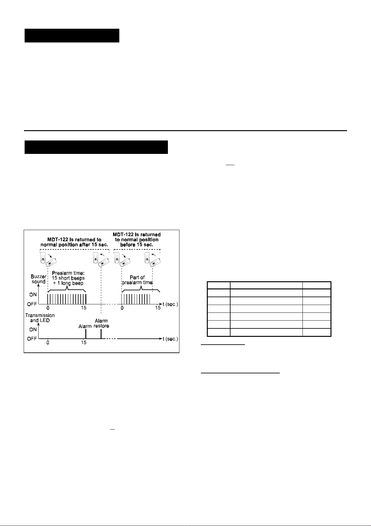
Figure 5 - Preparation for Use
4.2 Teaching the Target Receiver
It is recommended to use the MDT-122 with MCR-308 as a target
receiver (for other receiver types, see section 1). Each of the four
MDT-122 alarm types (Panic, Man-Down, Pull-Cord, Test)
activates a different MCR-308 output, to provide any desired
function, like sounding a siren or activating an automatic dialer
(for delivering a prerecorded voice/digital message to
predetermined addresses).
To provide the desired alarms, the target receiver must “learn” to
identify the Man-down transmitter transmission. For the learning
process, refer to the relevant receiver installation instructions
document. If MCR-308 is used as a target receiver, refer to
document DE3191, paragraphs 3-5 and 3-7 to 3-9.
4.3 Test
Simulate all the actions that are shown in figure 4 and verify that
proper buzzer, LED and transmissions functions are performed.
5
55
5. NOTES AND WARNINGS
. NOTES AND WARNINGS. NOTES AND WARNINGS
. NOTES AND WARNINGS
5.1 Product Limitations
Visonic wireless systems are very reliable and are tested to high
standards. However, due to low transmitting power and limited
range (required by FCC and other regulating authorities), there
are some limitations to be considered:
A. Receivers may be blocked by radio signals occurring on or
near their operating frequencies, regardless of the digital
code used.
B. Wireless equipment should be tested regularly to determine
whether there are sources of interference and to protect
against faults.
5.2 Compliance with Standards
WARNING! Changes or modifications to this unit not expressly
approved by the party responsible for compliance could void the
user's authority to operate the equipment.
The 315MHz version complies with FCC Rules Part 15.
Operation is subject to two conditions: (1) This device may not
cause harmful interference, and (2) this device must accept any
interference that may be received or that may cause undesired
operation.
The product has been tested and found to comply with the limits
for class B digital device, pursuant to part 15 of the FCC Rules.
These limits are designed to provide reasonable protection
against harmful interference in a residential installation. This
equipment generates, uses and can radiate radio frequency
energy and, if not used in accordance with the instructions, may
cause harmful interference to radio communications. However,
there is no guarantee that the interference will not occur in a
particular installation
WARRANTY
WARRANTYWARRANTY
WARRANTY
Visonic Ltd. and/or its subsidiaries and its affiliates ("the Manufacturer") warrants its
products hereinafter referred to as "the Product" or "Products" to be in conformance with
its own plans and specifications and to be free of defects in materials and workmanship
under normal use and service for a period of twelve months from the date of shipment by
the Manufacturer. The Manufacturer's obligations shall be limited within the warranty
period, at its option, to repair or replace the product or any part thereof. The Manufacturer
shall not be responsible for dismantling and/or reinstallation charges. To exercise the
warranty the product must be returned to the Manufacturer freight prepaid and insured.
This warranty does not apply in the following cases: improper installation, misuse,
failure to follow installation and operating instructions, alteration, abuse, accident or
tampering, and repair by anyone other than the Manufacturer.
This warranty is exclusive and expressly in lieu of all other warranties, obligations or
liabilities, whether written, oral, express or implied, including any warranty of
merchantability or fitness for a particular purpose, or otherwise. In no case shall the
Manufacturer be liable to anyone for any consequential or incidental damages for breach
of this warranty or any other warranties whatsoever, as aforesaid.
This warranty shall not be modified, varied or extended, and the Manufacturer does not
authorize any person to act on its behalf in the modification, variation or extension of this
warranty. This warranty shall apply to the Product only. All products, accessories or
attachments of others used in conjunction with the Product, including batteries, shall be
covered solely by their own warranty, if any. The Manufacturer shall not be liable for any
damage or loss whatsoever, whether directly, indirectly, incidentally, consequentially or
otherwise, caused by the malfunction of the Product due to products, accessories, or
attachments of others, including batteries, used in conjunction with the Products.
The Manufacturer does not represent that its Product may not be compromised and/or
circumvented, or that the Product will prevent any death, personal and/or bodily injury
and/or damage to property resulting from burglary, robbery, fire or otherwise, or that the
Product will in all cases provide adequate warning or protection. User understands that a
properly installed and maintained alarm may only reduce the risk of events such as
burglary, robbery, and fire without warning, but it is not insurance or a guarantee that such
will not occur or that there will be no death, personal damage and/or damage to property
as a result.
The Manufacturer shall have no liability for any death, personal and/or bodily injury
and/or damage to property or other loss whether direct, indirect, incidental,
consequential or otherwise, based on a claim that the Product failed to function.
However, if the Manufacturer is held liable, whether directly or indirectly, for any loss or
damage arising under this limited warranty or otherwise, regardless of cause or origin, the
Manufacturer's maximum liability shall not in any case exceed the purchase price of the
Product, which shall be fixed as liquidated damages and not as a penalty, and shall be the
complete and exclusive remedy against the Manufacturer.
Warning: The user should follow the installation and operation instructions and among
other things test the Product and the whole system at least once a week. For various
reasons, including, but not limited to, changes in environmental conditions, electric or
electronic disruptions and tampering, the Product may not perform as expected. The user
is advised to take all necessary precautions for his /her safety and the protection of
his/her property.
6/91
VISONIC LTD. (ISRAEL): P.O.B 22020 TEL-AVIV 61220 ISRAEL. PHONE: (972-3) 645-6789, FAX: (972-3) 645-6788
VISONIC INC. (U.S.A.): 10 NORTHWOOD DRIVE, BLOOMFIELD CT. 06002-1911. PHONE: (860) 243-0833, (800) 223-0020 FAX: (860) 242-8094
VISONIC LTD. (UK): FRASER ROAD, PRIORY BUSINESS PARK, BEDFORD MK44 3WH. PHONE: (0870) 730-0800 FAX: (0870) 730-0801
Internet Web Site: www.visonic.com
VISONIC LTD. 2001 MDT-122 , DE2292U (REV. 1, 1/2001).
Other Visonic Transmitter manuals

Visonic
Visonic MCT-211 User manual

Visonic
Visonic TOWER 10 AM - User manual

Visonic
Visonic MCT-124 User manual

Visonic
Visonic MCT-211 User manual

Visonic
Visonic MCT-212 AMBER User manual

Visonic
Visonic MCT-211 User manual

Visonic
Visonic MCT 320 User manual

Visonic
Visonic WT-211 User manual

Visonic
Visonic CodeSecure MCT-237 User manual

Visonic
Visonic PB-101PG2 User manual

Visonic
Visonic MCT-101 User manual

Visonic
Visonic MCT-330 User manual

Visonic
Visonic MCT-212 User manual

Visonic
Visonic MCT-241 User manual

Visonic
Visonic MCT-237 User manual

Visonic
Visonic WT-104 User manual

Visonic
Visonic MCT-201 User manual

Visonic
Visonic MCT-212 AMBER User manual

Visonic
Visonic WT-101A User manual

Visonic
Visonic WT-100 User manual