Visual Productions CUECORE1 User manual
CUECORE1
MANUAL
© VISUAL PRODUCTIONS BV WWW.VISUALPRODUCTIONS.NL

Revision History
Revision Date Author(s) Description
10 08.05.2017 ME General update.
11 19.06.2018 ME Added: Rackmount accessory. Re-
placed VisualTouch info by Kiosc. Up-
dated vManager chapter to reflect
app-store distribution.
2


c
2018 Visual Productions BV. All rights reserved.
No parts of this work may be reproduced in any form or by any means - graphic,
electronic, or mechanical, including photocopying, recording, taping, or infor-
mation storage and retrieval systems - without the written permission of the
publisher.
While every precaution has been taken in the preparation of this document,
the publisher and the author assume no responsibility for errors or omissions,
or for damages resulting from the use of information contained in this docu-
ment or from the use of programs and source code that may accompany it. In
no event shall the publisher and the author be liable for any loss of profit or
any other commercial damage caused or alleged to have been caused directly or
indirectly by this document.
Due to the dynamic nature of product design, the information contained in
this document is subject to change without notice. Revisions of this informa-
tion or new editions may be issued to incorporate such changes.
Products that are referred to in this document may be either trademarks and/or
registered trademarks of the respective owners. The publisher and the author
make no claim to these trademarks.
4

Declaration of Conformity
We, manufacturer Visual Productions BV, herby declare under sole responsibility, that
the following device:
CueCore
Is in conformity with the following EC Directives, including all amendments:
EMC Directive 2004/108/EG
And the following harmonized standards have been applied:
NEN-EN-IEC 61000-6-1:2007
NEN-EN-IEC 61000-6-3:2007
Full name and identification of the person responsible for product quality and
accordance with standards on behalf of the manufacturer
Date: Place:
February 1
st
, 2012 Haarlem, The Netherlands
ing. Maarten Engels
Managing Director
Visual Productions BV

Chapter 1
Introduction
Thank you for choosing the CueCore1. This manual discussing setting up the
units and programming the lighting cues, show-control-actions and various other
features.
The CueCore1 is solid-state lighting controller, designed without any moving
parts, it is build for reliability and durability.
The unit is aimed at providing a control solution for (semi-)permanent light-
ing projects. The CueCore1 primary control signal is DMX-512, the protocol
used for entertainment, theatre and most LED lighting fixtures. Next to DMX-
512 this controller also supports a range of other protocols; allowing communi-
cation with various other equipment.
An internal web-server provides the web-interface through which you can
program the CueCore1. A modern browser is required to access this web-
interface during set-up. A browser or computer is not required for standalone
use after the initial set-up.
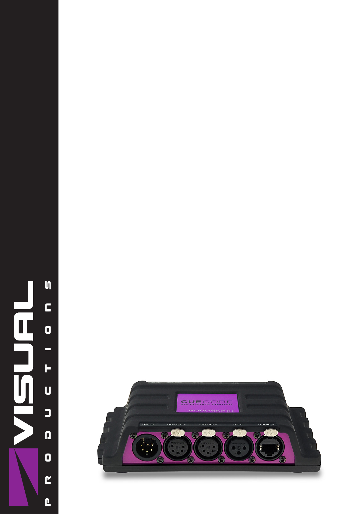
Figure 1.1: CueCore1
This manual discusses setting up and programming the unit. Chapter 2
provides background information on the communication protocols used the
CueCore1. Chapters 3 and 4 cover how to set up the unit and configure the
network connection.
The CueCore1 includes a licence for CueluxPro; it unlocks two universes.
CueluxPro is a professional lighting control software from Visual Productions
and is discussed in chapter 5.
Chapters 6 and 7 cover creating and recording both static and dynamic
lighting scenes.
Programming the triggering and converting functionality is explained in ch-
pater 8 on page 27.
6

At the time of writing this manual the CueCore1’s firmware was at version
1.90.
The CueCore1 is end-of-life and is not recommended for new designs. It has
been superseded by CueCore2.
1.1 Features
The feature set of the CueCore1 includes:
•2 DMX output ports
•1 DMX input port
•MIDI input and output
•SMPTE input
•4 GPI contact-closure ports
•Art-Net
•TCP, UDP & OSC
•Scheduling with Real-Time clock, weekdays and sunrise/sunset
•Desktop or DIN Rail mounted
•Kensington lock
•Locked power cable protection
•Web-based user-interface for programming
•PoE (Power Over Ethernet) Class I
•Compatible with IoCore, QuadCore, TimeCore and B-Station
•Bundled with CueluxPro, vManager and Kiosc software
1.2 What’s in the box?
The CueCore1 packaging contains the following items (see figure 1.2):
•CD-ROM
•CueCore1
•Power supply
7

Figure 1.2: CueCore1 box contents
1.3 Saving data to memory
This manual will describe how to configure the CueCore1 and program con-
versions, action, etc. The unit’s web-interface is used for editing these kinds
of elements. When changes are made, these changes are directly stored in the
RAM memory of the CueCore1 and the programming will directly influence the
behaviour of the unit. RAM memory is, however, volatile and its content will be
lost through a power cycle. For this reason the CueCore1 will copy any changes
in the RAM memory to its onboard flash memory. Flash memory retains its
data even when not powered. The CueCore1 will load all its data back from the
flash memory upon startup.
This memory copy process is conducted automatically by the CueCore1 and
should not be of any concern of the user. One point of consideration is, how-
ever, that after making a change the unit should be given time to perform the
copy to flash. As a rule of thumb, do not disconnect the power from the device
within 30 seconds from making a programming change.
1.4 Further Help
If, after reading this manual, you have further questions then please consult the
online forum at http://forum.visualproductions.nl/forum for more tech-
nical support.
8

Chapter 2
Protocols
The CueCore1 is fitted with several communication ports and supports various
protocols. This chapter describes these protocols and to which extent they are
implemented in the CueCore1
2.1 DMX-512
DMX-512 is the standard communication protocol for stage lighting. Its official
name is E1.11-2008 USITT DMX512-A. Nowadays the reach of the DMX proto-
col has extended beyond entertainment lighting and is also used for architectural
lighting. Originally one DMX network contained 512 channels which is called a
’universe’. With the growing size and complexity of lighting systems it is now
very common for a system to compose of multiple universes, each conveying 512
channels. It is advised to use a shielded twisted pair cable for DMX cabling.
The cable should be terminated with an 120 Ohm resistor.
DMX-512 is a very successful protocol with, however, a few limitations. The
maximum number of attached devices is limited to 32 and they all have to be
connected in bus-topology having one cable running via each device. Further-
more, a DMX-512 cable should not be longer than 300 meters.
The DIN Rail RdmSplitter from Visual Productions (See figure 2.1) helps tackle
those inconvenient limitations. The Splitter takes a DMX signal and sends it
out again on its 6 DMX output ports for scaling group topology. Each output
port is capable of driving 32 more devices. The Splitter can also function as a
signal booster as each port supports another 300 meter long connection.
The CueCore1 has two DMX output ports and one input Port. It is able to
control 1,024 channels. Figure 2.2 shows the pinout of the connectors. The
CueCore1 can receive 512 channels for recording or converting into Art-Net.
The DMX input port can also be used for triggering, however, for this purpose
the CueCore1 is only capable of monitoring 50 DMX channels. By default these
are channels 1-50. This block of channels can be moved up by changing the
’DMX Input’ number in the settings page (See page 37).
9

Figure 2.1: Visual Productions’ RdmSplitter
Figure 2.2: DMX Pinout
2.2 Art-Net
The Art-Net protocol primarily transfers DMX-512 data over Ethernet. The
high bandwidth of an Ethernet connection allows Art-Net to transfer up to 256
universes. The data sent out for Art-Net does put a certain load on the network,
therefore it is recommended to disable Art-Net when not in use. The CueCore1
can receive and send out two DMX universes over Art-Net. Art-Net can be used
for recording, converting and creating triggers in the show control programming.
2.3 GPI
The CueCore1 features four General Purpose Inputs (GPI) ports that can be
connected to external equipment, switches and sensors. State changes on these
GPI ports can be used to trigger programmed events inside the CueCore1.
10
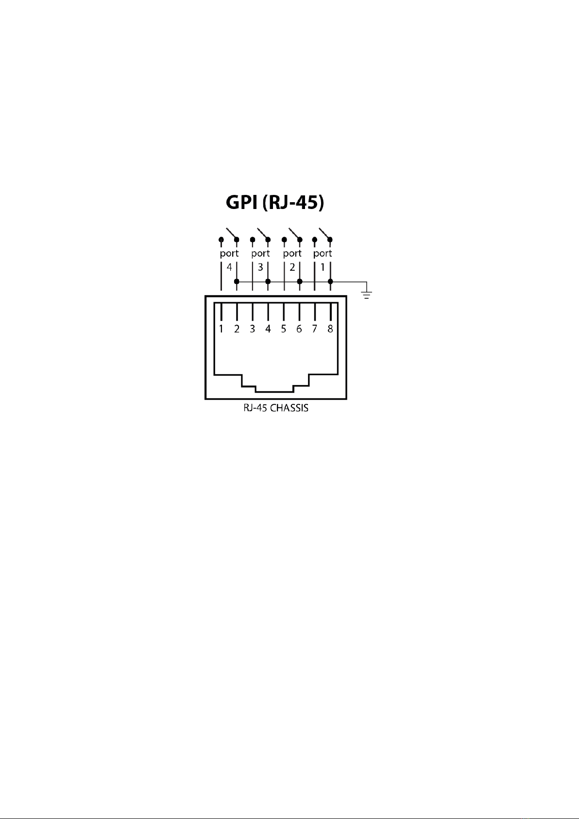
For each GPI port’s pin the signal is held up by an internal pull-up resistor
and results in a logic ’0’. The external equipment is intended to short the port’s
pin to the provided ground pin. This short will create a logic ’1’.
Please refer to figure 2.3 for the pinout of the GPI connector.
Figure 2.3: GPI Pinout
Programming events based on GPI activity is done in the Show Control page,
which is discussed on page 27. If your project requires more than 4 GPI contacts
then you can expand the GPI ports by connecting one or more IoCore modules
to your CueCore1. The module can be connected through OSC, UDP, Art-Net
or DMX.
2.4 UDP
User Datagram Protocol (UDP) is a simple protocol for sending messages across
the network. It is supported by various media devices like video projectors and
Show Controllers. It does not incorporate error checking, therefor it is faster
than TCP but less reliable.
The CueCore1 responds to incoming UDP messages by programming custom
messages in the Show Control page (see page 27). This is also the place where
to program outgoing UDP messages.
11

2.5 OSC
Open Sound Control (OSC) is a protocol for communicating between software
and various multi-media type devices. OSC uses the network to send and receive
messages, it can contain MIDI and custom information. There are apps avail-
able for creating custom-made user interfaces on iOS (iPod, iPhone, iPad) and
Android. These tools allow to program fool-proof user-interfaces for controlling
the device. E.g. TouchOSC from http://hexler.net/software/touchosc.
There is a TouchOSC layout available from http://www.visualproductions.
nl/products/b-station.html that is configured to control the playbacks of
the CueCore1.
The CueCore1 responds to incoming OSC messages by programming custom
messages in the Show Control page (see page 27). This is also the place where
to program outgoing OSC messages.
2.6 MIDI
The MIDI protocol is intended for inter-connecting musical devices such as syn-
thesisers and sequencers. Furthermore, this protocol is also very suitable to
send triggers from one device to another and is often used to synchronise audio,
video and lighting equipment. There is also a large collection of MIDI con-
trol surfaces available; user-interface consoles with knobs, (motorised-)faders,
rotary-encoders, etc.
The CueCore1 is fitted with a MIDI input and MIDI output port. It supports
receiving and sending MIDI messages like NoteOn, NoteOff, ControlChange and
ProgramChange.
2.7 SMPTE
SMPTE is timecode signal which can be used to synchronise audio, video, light-
ing and other show equipment. The CueCore1 supports receiving SMPTE that
is transferred as an audio signal, also know as LTC timecode.
12

Chapter 3
Setting up
This chapter discusses how to set up the IoCore.
3.1 Mounting
The device can be placed desktop or it can be DIN Rail mounted. The device
is prepared for DIN Rail mounting by using the ’DIN rail holder TSH 35’ from
Bopla (Product no. 22035000).
Figure 3.1: Bopla DIN rail adapter
This adapter is - amongst others - available from:
•Farnell / Newark (order code 4189991)
•Conrad (order code 539775 - 89)
•Distrelec (order code 300060)
3.2 Rackmount
There is an adapter available for mounting the CueCore1 into a 19” rack . The
rackmount adapter is 1 HE and is sold separately. It fits two units, however, it
is supplied with one position closed by a blind panel, see figure 3.2.
13
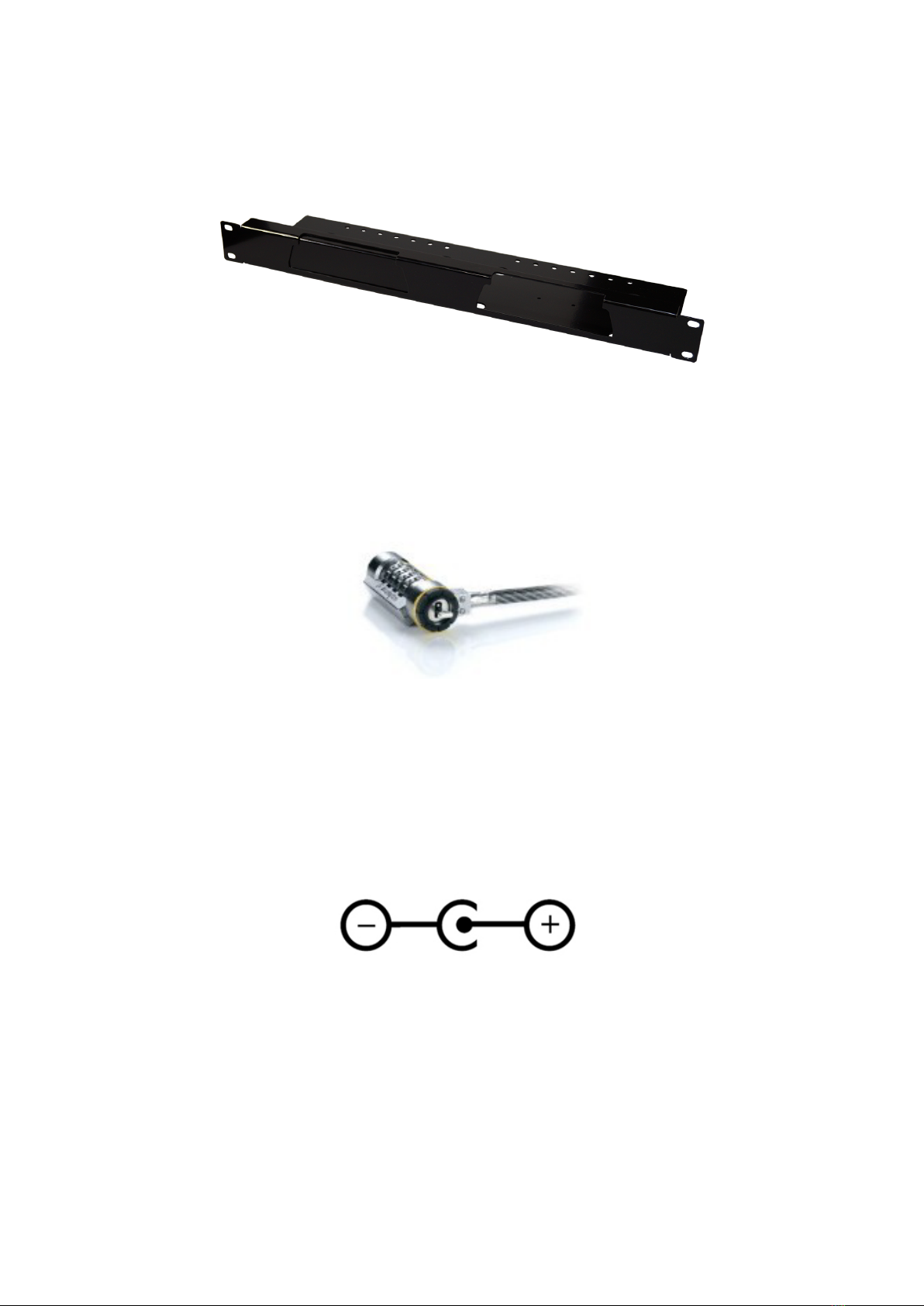
Figure 3.2: Rackmount adapter
3.3 Kensington Lock
The device can be secured by using a Kensington style laptop lock.
Figure 3.3: Kensington lock
3.4 Power
The CueCore1 requires a DC power supply between 9 and 12 Volt with a mini-
mum of 500mA. The 2,1 mm DC connector is center-positive.
The CueCore1 is also Power-over-Ethernet (PoE) enabled (starting from
hardware version v1.6). It requires PoE Class I.
Figure 3.4: DC polarity
14
Chapter 4
Network
The CueCore1 is a network capable device. A network connection between
between a computer and the unit is required to configure and program the
CueCore1, however, once the device is programmed then it is not necessary
anymore for the CueCore1 to be connected to an Ethernet network.
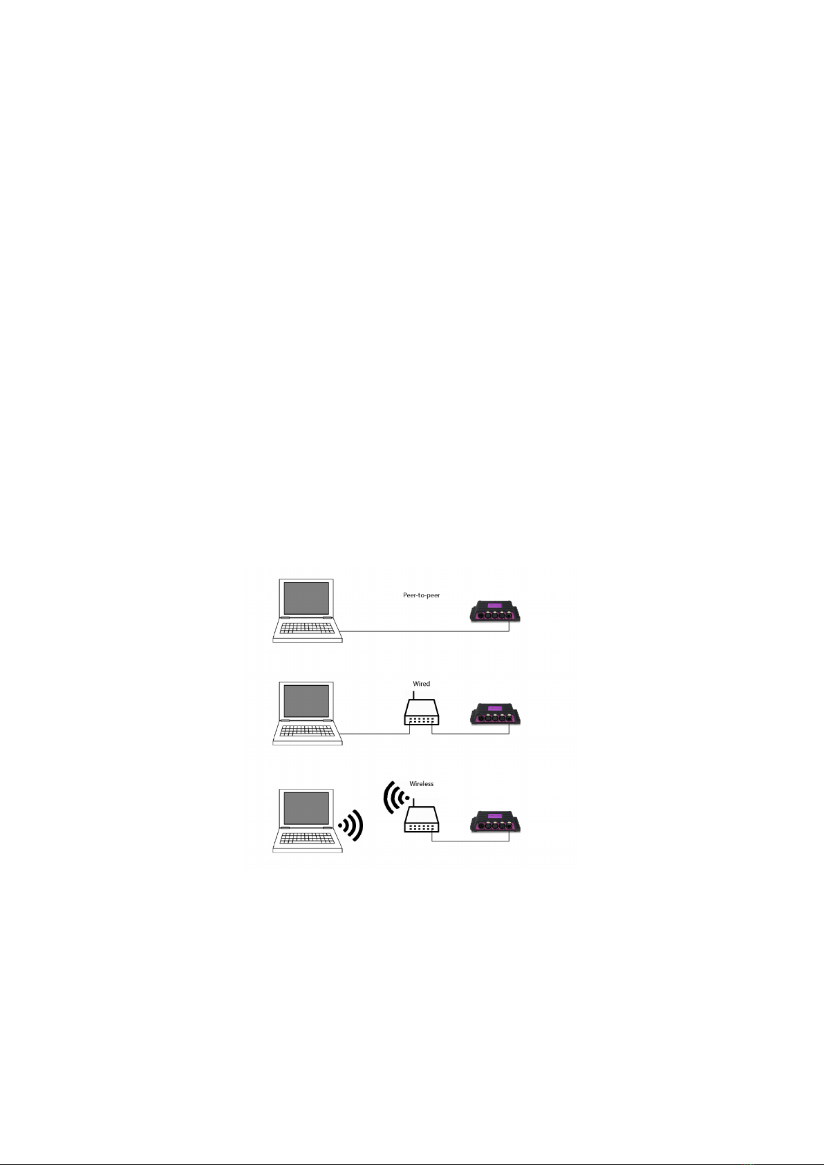
There are multiple arrangements possible for connecting the computer and the
CueCore1. They can be connected peer-to-peer, via a network switch or via
Wi-Fi. Figure 4.1 illustrates these different arrangements.
Figure 4.1: Network arrangements
The Ethernet port on the CueCore1 is auto-sensing; it does not matter whether
a cross or straight network-cable is being used.
15

4.1 IP Address
The CueCore1 only supports static IP addresses. By default, the CueCore1 is
set to 192.168.1.10.
There are three ways to change the IP address setting of the CueCore1.
•vManager can be used to detect a CueCore1 on the network. Once found,
the vManager software (figure ??) allows for changing the IP address and
subnet mask.
•If the IP address is already known then browsing to this address using
the computer’s browser will show the CueCore1’s web-interface. The
Settings page on this web-interface enables changing the IP address and
subnet mask settings.
•By pressing the reset button on the device for 3 seconds, it will reconfig-
ure the unit to the factory default IP address and subnet mask. No other
settings will be changed. The default IP address is 192.168.1.10 with the
subnet mask set to 255.255.255.0.
Figure 4.2: Reset button
4.2 Access via Internet
The CueCore1 can be accessed through the Internet. There are two ways to
achieve this: Port-Forwarding and VPN.
•Port-Forwarding Is relatively easy to setup in the router. Each router
is different so it is advised to consult the router’s documentation (some-
times it is revered to as NAT or Port-Redirecting). Please note that port
forwarding is not secure, since anybody could access the CueCore1 this
way.
•Accessing via a Virtual Private Network (VPN) tunnel requires more
setup efforts, also the router needs to support the VPN feature. Once set
up, this is a very secure way to communicate with the CueCore1. A VPN
is a network technology that creates a secure network connection over a
public network such as the Internet or a private network owned by a service
16

Chapter 5
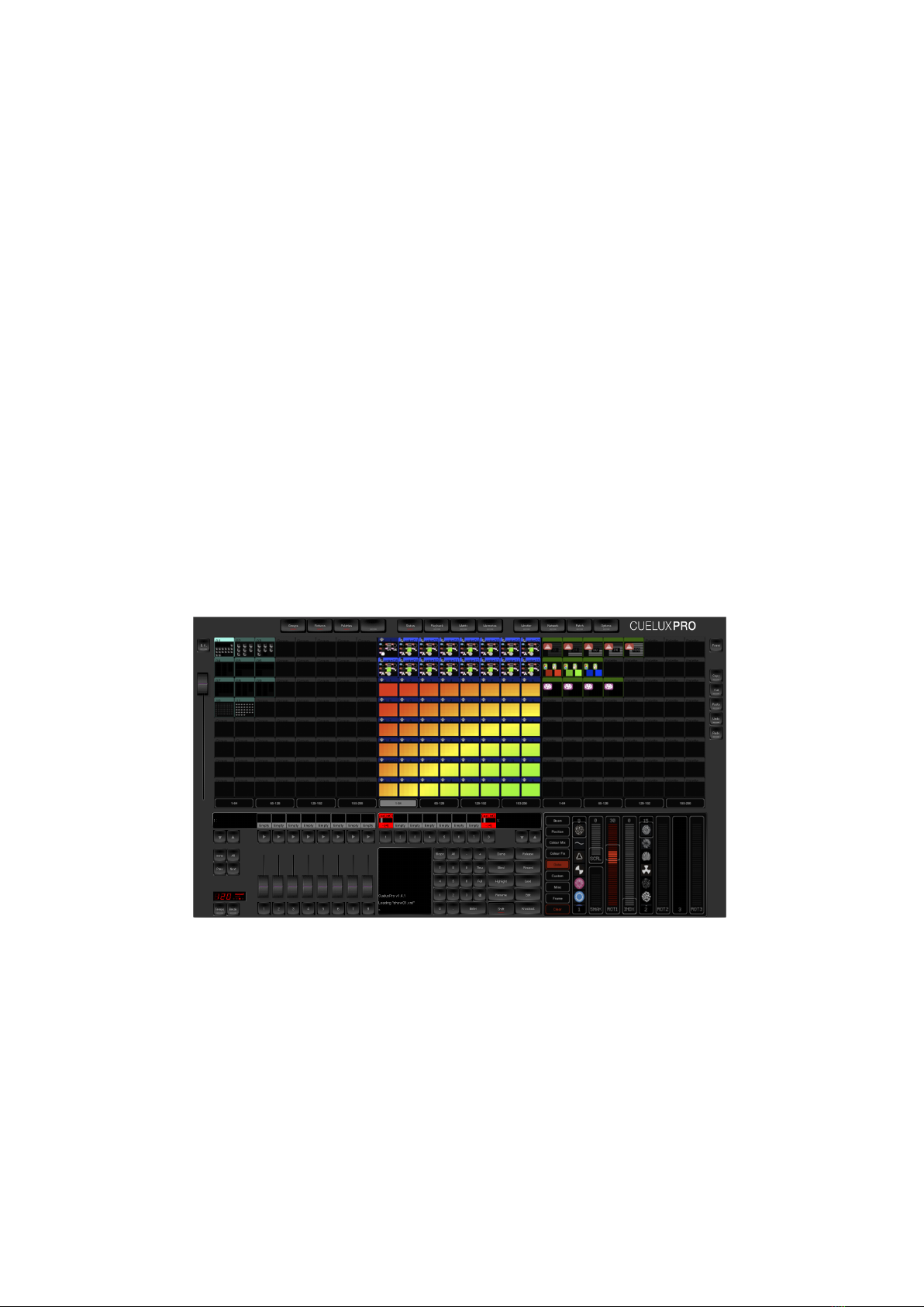
CueluxPro
The CueCore1 includes a software licence for CueluxPro. CueluxPro is powerful
software application for controlling DMX lighting, it features fixtures, groups,
palettes, pixel-mapping, timeline-editor and fx-generator (See figure 5.1). Each
CueCore unlocks 2 universes in CueluxPro, multiple CueCore1 units can be used
together to create one large control system. You can also use CueluxPro as a
programming-tool for the CueCore, using powerful software features to upload
your cues and recorders into the CueCore1’s memory.
Figure 5.1: CueluxPro
For compatibility with CueluxPro the CueCore1 needs to run firmware v1.55
or higher.
Please refer to the CueluxPro manual for more information.
18

Chapter 6
Console
The Console page allows you to program and manually playback lighting scenes.
Figure 6.1: Console page
6.1 Overview
A Cue is a lighting scene, a state at which all DMX channels are set to a specific
value. A sequence of multiple Cues - running one-by-one is called a Cue-list.
The Lighting Console function features as 1 Cue-list containing 256 Cues. Each
Cue stores the values for all 1,024 DMX channels. The number of Cues is fixed,
however, Cues can be left unused.
6.2 Run Mode
The Lighting Console can be set in either PLAY or EDIT mode. The difference
between the modes is the EDIT mode ignores the fade, hold and link values.
The EDIT mode is more convenient during programming the Cues.
19

6.3 Unit
A DMX channel can be set between 0 (minimum) and 255 (maximum). The
DMX levels are shown in these decimal values if the UNIT is set to DEC. When
UNIT is set to % the levels are shown in the range of 0% and 100%. The UNIT
setting also influences how you enter the values via the Command Line interface.
E.g. if you would like to set a channel to the maximum level you would type in
value ’255’ when the unit is set DEC and you would type in ’100’ when it was
is set to
6.4 Programming a Cue
First enable the EDIT mode and select the desired Cue by using the GO+ and
GO- buttons. You see the number of the current Cue in the bottom left-hand
corner of the screen. Use the command line interface (CLI) to change the value
of the channel. The CLI is known from theatre lighting consoles and provides a
fast way of setting values for one or multiple channels. Examples of the CLI’s
usage are:
Command Function
1 @ 50 <ENTER> Sets channel 1 at 50% (or at DMX value 50 when
DEC unit is selected)
1 + 2 @ <FULL> Sets channel 1 and 2 at maximum value
1 <THRU> 3 @ 0 Sets channels 1 till 3 at minimum value
1 <THRU> 3 + 5 @ 0 Sets channels 1, 2,3, and 5 at minimum value
<ALL> @ 100 <ENTER> Sets channels 1 till 1024 at 100% (or at DMX
value 100 when DEC unit is selected)
1 @ + 10 <ENTER> Increases channel 1 value with 10
<ALL> @ 20 <ENTER> Decreases all channels’ value by 20
6.5 Capture a Cue
Alternatively to programming a Cue through the CLI it is also possible to record
a Cue from the DMX input port or incoming Art-Net universes. To capture from
DMX, simply connect your external DMX-512 source and set it to output the
desired Cue, then press the DMX Capture button. Only the first 512 channels
will be recorded, channels 513 till 1024 are left unchanged. For capturing from
Art-Net please make sure that the universe settings for incoming Art-Net match
the universes at your Art-Net source. Press the Art-Net Capture button and
all 1,024 channels are recorded in the Cue.
6.6 Timing
You can specify the cross-fade time between two Cues by setting the Cue’s fade
time (expressed in seconds). Also you can determine for how long the Cue
20
Table of contents
Other Visual Productions Dj Equipment manuals


Popular Dj Equipment manuals by other brands


TECshow
TECshow ALFIE WASH BM user manual

LCG
LCG ULTRA WASH ZOOM LCG-MHW730Z user manual

Traxon
Traxon ecue Vista Plus 1x200W RGBW installation guide

VanGaa Lighting
VanGaa Lighting Swift Aura 1925Z user manual

SUPER-CAN
SUPER-CAN SCL-BLUELOVE-B user manual

JB-Lighting
JB-Lighting Varycolor MICRO 150HTI Short manual


