8
Installation Instructions.
The Sara 3000 is delivered to you in fully
assembled state.
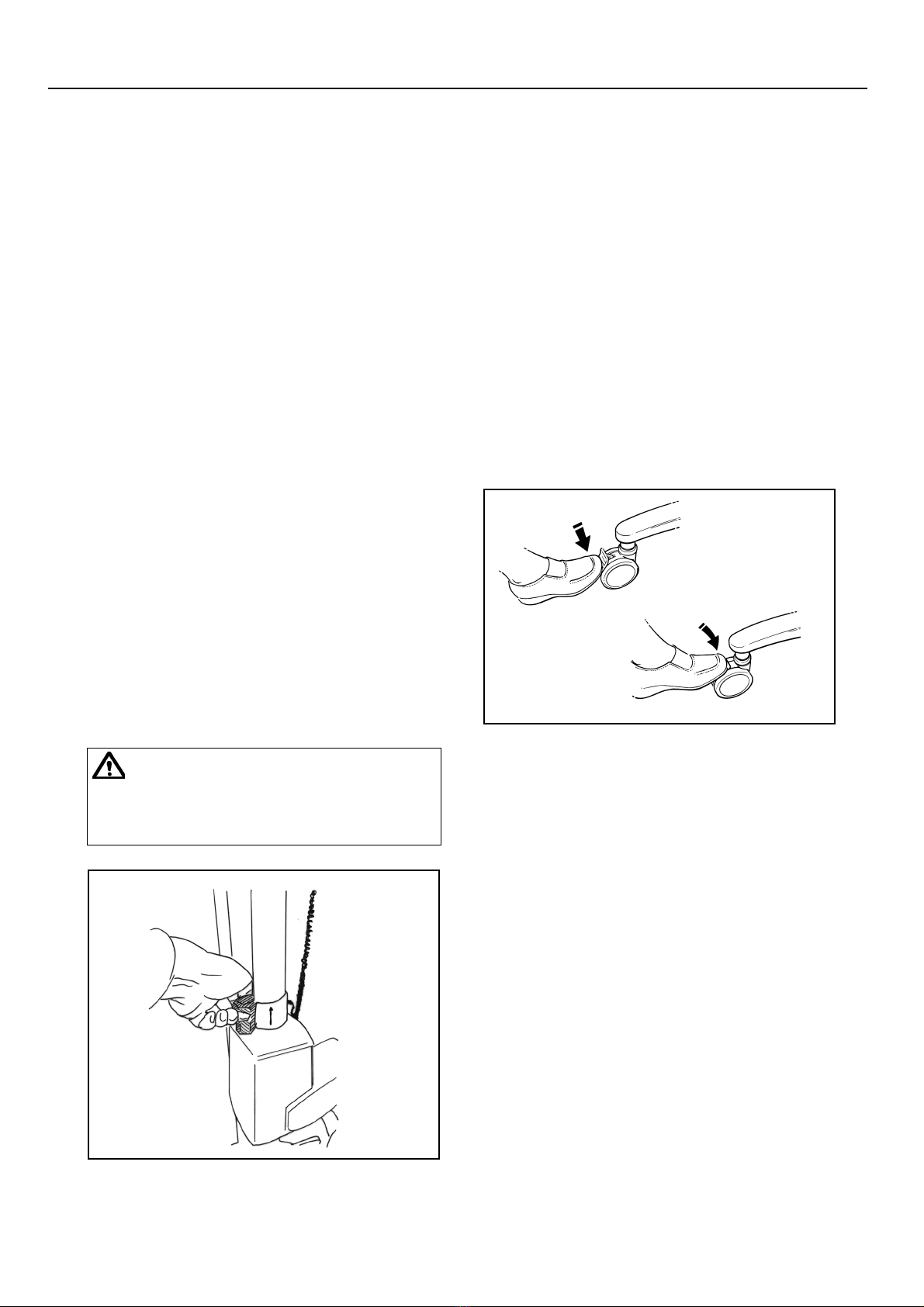
Unpack the battery pack supplied, and fully
charge it for a minimum of 24 hours, see
“Battery Charging” section.
When the battery pack is fully charged,
disconnect the electric power, remove the
pack from the charger, and insert it fully back
into the Sara 3000 battery compartment
located at the rear of the mast.
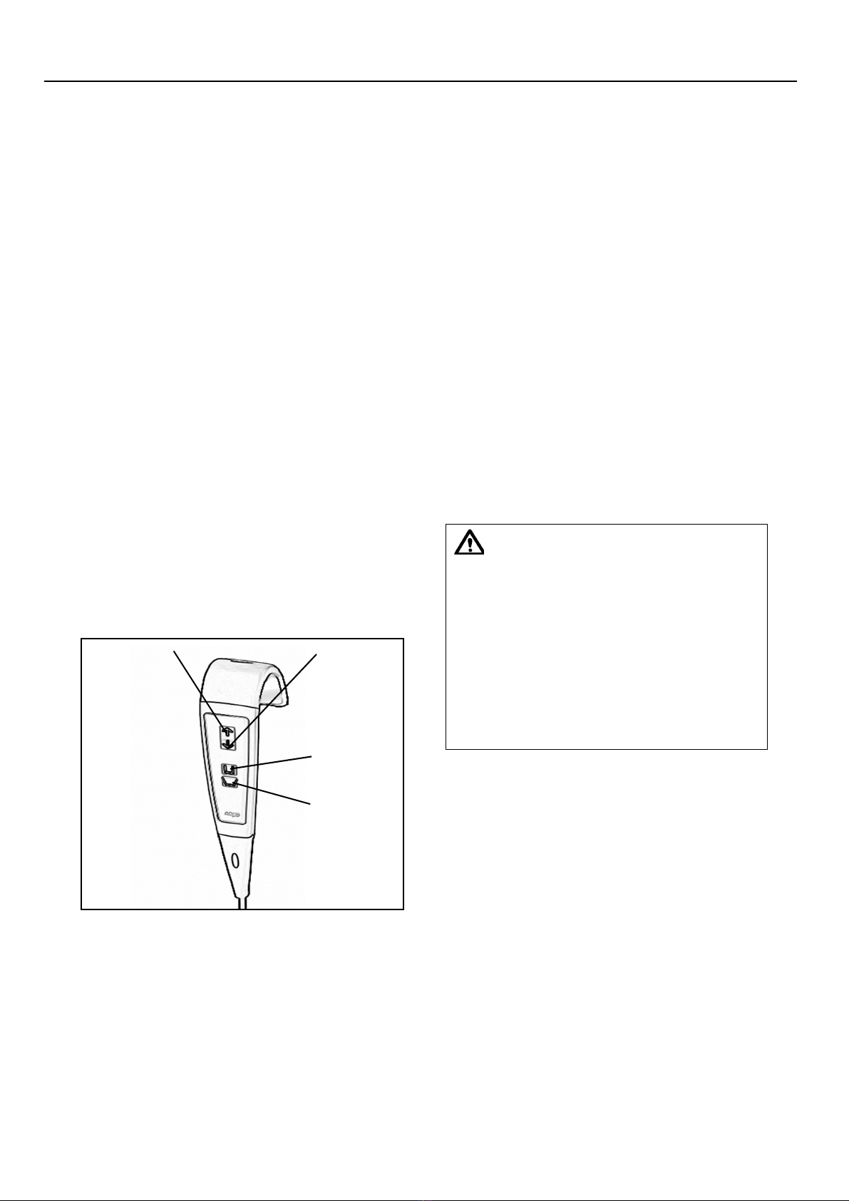
Features and functions
Control Handset: A semi-remote control unit
attached to the Sara 3000 by an extending
cable. The handset controls are for the raising
/ lowering and chassis leg opening/closing
functions. Direction arrows adjacent to the
buttons indicate each function (see Fig. 2). If
pressure is released from any button during
use, the powered movement will stop
immediately.
“Raise” button “Lower”
“Chassis legs
open” button
“Chassis legs
close” button
Fig. 2
Dual control switch:- as an option to the
semi-remote control handset, the raising and
lowering of the resident support arms can be
controlled from this switch, situated on the
front of the electronics/battery compartment.
A label adjacent to the switch is for function
identification (see Fig. 1). This switch will
function even if the handset cable has been
unplugged.
Emergency Stop Button (red) (see Fig. 1): If
you have to immediately stop any powered
movement, (other than by releasing pressure
on the button on the control handset), press
the red “stop button” located on the control
panel above the battery. This function can also
be used to ensure that powered operation
cannot accidently start when either using the
Sara 3000, or leaving it in storage or
unattended.
Once the red Stop Button has been operated,
the green reset button has to be pushed into
reset the red stop button. Now the Sara 3000
can be operated again.
Warning: The caregiver shall be aware
that from the moment the lowering and
raising functions are used, the resident
support arms shall follow the
movement of the used function.
If the resident support arms do not
follow the movement indicated by the
use of the pressed control button,
release the button immediately and
check for obstructions.
Before removing the obstruction, make
sure the resident will be supported and
in a safe position at all time.
The following safety features have been put in
place;
Automatic Cut Out - for use when Raising:
(see Fig. 1) (not a caregiver / operator control
but a function built into the electronics)
If the equipment is inadvertently overloaded
(trying to raise a resident heavier than
permitted), an automatic ‘cut out’ operates to
prevent the Sara 3000 lifting a load in excess of
the safe working load; this will stop the lift
motion automatically. If this automatic cut out
occurs, the electronics will reset when the
button on the handset is released. After this,
the resident can be lowered, by pressing the
“lower” function button on the handset.
Remove the resident from the equipment.
Product Description and Handling Instructions