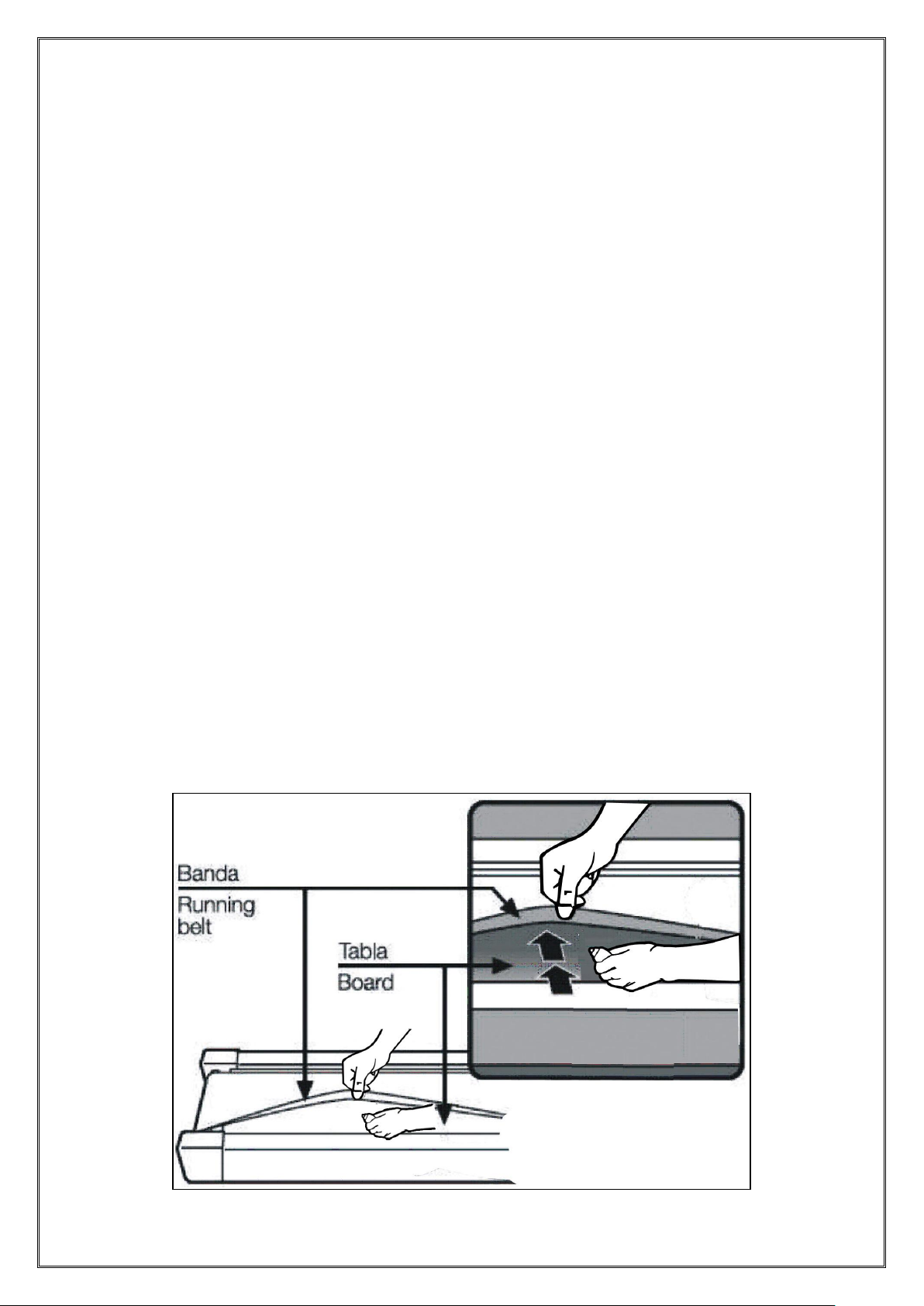
VIVA FITNESS T131 User manual

VIVA FITNESS
TREADMILL
OWNER’S MANUAL
ITEM NO. T131

- 1 -
WARNING
Read all instruction carefully before use this product. Retain this owner’s manual for the
future’s reference:
----When using this treadmill, keep attaching the safety pull pin rope to your clothes.
----When you are running, keep your hand swinging natural, stare frontward, never look adown at your
feet.
----Add the speed step by step when running.
----When emergency happens, take away the “emergent stop button” immediately.
----Leave the treadmill after the running belt stop stably.
Caution: Read the assembly instruction carefully, follow the instruction when
assemble.
ATTENTION
01- Before starting any exercise program, consult with your physician or health professional.
02- Check all the bolts locked.
03- Never put the treadmill in the wetness area, or it will cause troubles.
04- We take no responsibility for any troubles or hurts due to above reasons.
05- Dress sport clothes and shoes before running.
06- Do not do exercise in 40 minutes after meal.
07- To prevent hurts, please warm up before exercise.
08- Consult with doctor before exercise if you have high blood pressure.
09- The treadmill is only used for adults.
10- Provide the olds, children and handicapped with good care, guide and supervision.
11- Do not plug anything into any parts of this equipment, or it may damage.
12- Do not connect line to the middle of cable; do not lengthen cable or change the cable plug; do not put
any heavy thing on cable or put the cable near the heat source; forbid using socket with several
holes, these may cause fire or people may be hurt by the power.
13- Cut off the power when the equipment is not used. When the power is cut off, do not pull the power
line to keep the wire unbroken.
14. Pulse monitor data may not be accurate, which can not be used for medical purpose. Over-exercise
may cause injury, even death. If you have a feeling of dizziness, sickness or other abnormal

- 2 -
symptoms, please stop training and consult a doctor immediately.
15. Maximum weight of User: 110KGS.
IMPORTANT SAFETY PRECAUSTION
1. Plug the power cord of the treadmill directly into a dedicated grounded circuit. This product must be
grounded. If it has breakdown, grounding provides a path of least resistance for electric current to reduce
the risk of electric shock.
2. Position the treadmill on a clear, level surface. Do not place the treadmill on thick carpet as it may
interfere with proper ventilation. Do not place the treadmill near water or outdoors.
3. Position treadmill so that the wall plug is visible and accessible.
4. Never start the treadmill while you are standing on the walking belt. After turning the power on and
adjusting the speed control, there may be a pause before the walking belt begins to move, always stand
on the foot rails on the sides of the frame until the belt is moving.
5. Wear appropriate clothing when exercising on the treadmill. Do not wear long, loose fitting clothing
that may be caught in the treadmill.Always wear running or aerobic shoes with rubber soles.
6. Make sure the power supply is connected and the safety lock is effective before using the treadmill. Fit
one side of the safety lock on the treadmill and clip the other side on your clothes or belt, which will
enable you to pull off the safety lock promptly in an emergency.
7. Always unplug the power cord before remove the treadmill motor cover.
8. Make sure there is no less than 2*1m free space behind the treadmill.
9. Keep small children away from the treadmill during operation.
10. Always hold the handrails when initially walking or running on the treadmill, until you are comfortable
with the use of the treadmill.
11.Always attach the safety pull pin rope to your clothing when using the treadmill. If the treadmill should
suddenly increase in speed due to an electronics failure or the speed being inadvertently increased, the
treadmill will come to a sudden stop when the pull pin is disengaged from the console.
12. In case of any Abnormality during the use process, please remove the safety lock immediately,
grasping the handlebar and jumping onto the two edgings, then get off the treadmill after it stops.
13. When the treadmill is not being used, the power cord should be unplugged and the safety pull pin
removed.
14. Put the safety key away from reach of the children. Minors must be accompanied by the adults when
using the treadmill.
15. Before starting any exercise program, consult with your physician or health professional. He or she
can help establish the exercise frequency, intensity (target heart zone) and time appropriate for your

- 3 -
particular age and condition. If you have any pain or tightness in your chest, an irregular heartbeat,
shortness of breath, feel faint or have any discomfort while you exercise, STOP! Consult your physician
before continuing.
16. If you observe any damage or wear on the mains plug or on any section of the mains lead then
please have these replaced immediately by a qualified electrician –do not attempt to change or repair
these yourself.
17. If the supply cord is damaged, it must be replaced by the manufacturer, its service agent or similarly
qualified persons in order to avoid a hazard.
18. Put your feet on the side rail before using the treadmill, and always attach the safety pull pin rope to
your clothing. Hold the handle bar before the running belt moving well (feel the running speed by your
single foot before using it). To avoid loss balance, please slow down the speed to the lowest or take off
the safety. And hold the handle bar to jump to the side rail when emergency or the safety key is not
attached.
19. Make sure to unplug the power cord and the treadmill has completely stopped before folding. Please
don’t operate it after folding the treadmill.

- 4 -
ASSEMBLY STEPS
STEP 1:
Open the package, take out all parts and place the main frame on the flat ground.
(NOTE: Please don’t cut down the packing straps right now.)
STEP 2:
1. Cut down the straps when the main frame was placed well. (Note: Don’t move it any
more)
2. Connect the Sensor wire (48) with Extension wire (49) together;
3. Lock the Upright tube (2, 3) on the Bottom frame (4) with the Allen bolt (45) and Washer
(18). (Note: Please don’t lock them tightly now.)

- 5 -
STEP 3:
1. First, connect the Computer connecting wire (50) with Extension wire (49) together, then
lock the Computer frame (56) on the Upright tube (2, 3) with the Allen bolt (45) and
Washer (18) as shown;
2. Lock the Allen bolt (45) on Upright tube (2, 3) and Bottom frame (4) tightly;
3. Lock the Base cover (61L/R) to the Bottom frame (4) tightly with the Cross tapping
screw (13).

- 6 -
STEP 4:
When you fold the machine:
Put your hands on place A, lift up the machine, then push it to the direction of the arrow
shown, stop it when you hear the Clip sound from the Cylinder (28).

- 7 -
STEP 5:
When you unfold the machine:
Grasp the place A by your hands, kick the place Bof Cylinder (28) by your right foot, push
the running board to the level of place C, then the running board will get down
automatically.
GROUNDING METHODS
This product must be grounded. If it should malfunction or breakdown, grounding provides
a path of least resistance for electric current to reduce the risk of electric shock.
This product is equipped with a cord having an equipment-grounding conductor and a
grounding plug. The plug must be plugged into an appropriate outlet that is properly

- 8 -
installed and grounded in accordance with all local codes and ordinances.
DANGER –Improper connection of the equipment-grounding conductor can result in a
risk of electric shock. Check with a qualified electrician or serviceman if you are in doubt as
to whether the product is properly grounded.
Do not modify the plug provided with the product –if it will not fit the outlet, have a proper
outlet installed by a qualified electrician.
This product is for use on a nominal 230-Volt circuit and has a grounding plug that looks
like the plug illustrated in below figure. Make sure that the product is connected to an outlet
having the same configuration as the plug.
No adapter should be used with this product.
TECHNICAL PARAMETER
ASSEMBLY SIZE
(mm)
1645 x750 x1375
POWER
AS ORDER
FOLDING SIZE
(mm)
795 x750 x1490
MAX OUTPUT
POWER
AS ORDER
RUNNING SURFACE
SIZE(mm)
420 x1260
INPUT CURRENT
AS ORDER
NET WEIGHT
51 KG
SPEED RANGE
0.8-12 KM/H
MAX
USER’S WEIGHT
110KG
INCLINE
MANUAL
Operation Instructions

- 9 -
1. Function specifications
1.1 Appearance of the electronic meter
1.2. Start
Normal startup after 3s counting backwards.
1.3. Number of programs
Manual, 9- Preset Programs, BODYFAT TEST, 3-Countdown Modes
1.4. Safety lock function
Removing the safety lock, “---” will be immediately displayed, the treadmill will stop
rapidly and alarm as “Bi-Bi-Bi”. Installing the safety lock, the electronic meter will be reset
after 2s of data display.
1.5. Key function
1.5.1. START/STOP:
“START” is start key, press “START” when the treadmill is in stop state, the treadmill
will be started and run, with the speed displayed as “0.8”. “STOP” is stop key, press
“STOP” when the treadmill is running, and all data will be reset, the system will
return back to manual mode after stable stop of the treadmill.
The two keys are on the handrail too.

- 10 -
1.5.2. Program key:
“PROG” is the program key. In standby status, press “PROG”to select manual
mode, auto program P1 –P9; manual mode is the default one under which the
default speed is 0.8km/h and the maximum running speed is 12km/h.
1.5.3. Mode key:
“MODE” is mode key, in standby status, press MODE key can select 3 kinds of
countdown operation mode from H-1 to H-3. H-1 is the time countdown mode; H-2 is
the distance countdown mode; H-3 is the calorie countdown mode; SPEED+ and
SPEED- will be used to set up relevant countdown value. After the completion of the
setting, press START can start the treadmill.
1.5.4. Speed keys:
“SPEED+” and “SPEED -” are acceleration and deceleration keys: They may be
used to adjust parameter setting when setting up parameters of the treadmill. When
the treadmill is running, they are used to adjust the speed for 0.1Km/time; for
long-time pressing for more than 2s, automatic continuous acceleration and
deceleration will be realized.
The two keys are on the handrail too.
1.5.5. Speed shortcut keys:
Direct speed adjustment in the operation status can be realized through speed
shortcut keys.
1.6. Display function
1.6.1 Speed display
Display the current running speed.
1.6.2. Lifting display
Display the current running lifting value.
1.6.3 Time display
Display the running time under manual mode or the countdown running time
under mode and programmed mode.
1.6.4. Distance display
Display the accumulated distance under manual and programmed mode or the
countdown distance under mode running state.
1.6.5. Heart rate display
When heart rate signals are detected, the heart shaped icon flashes and the
pulse value will be displayed.
1.6.6. Data display range of various parameters:
TIME: 0:00 –99.59(MIN)
DISTANCE: 0.00 –99.9(KM)
CALORIES: 0.0 –999 (C)
SPEED: 0.8 –12.0(KM/H)
PULSE: 50 –200 (BPM)

- 11 -
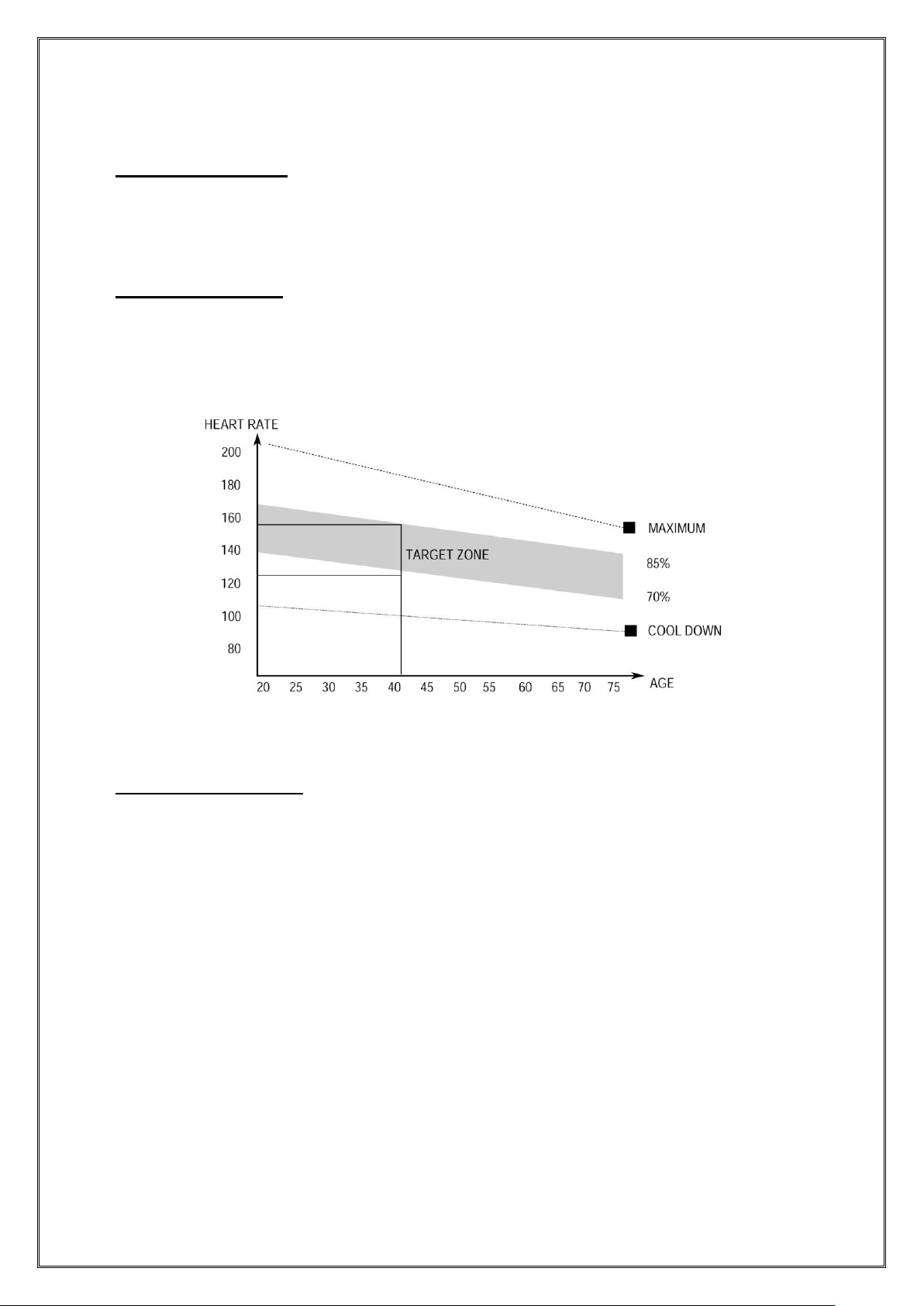
1.7. Heart rate measurement function
While the treadmill is connected to the power, hold the pulse tester for 5s and the
heart rate value will be displayed. The initial value is the actually measured heart
rate, and its display range is: 50-200 times/ minutes. In the heartbeat measurement
process, there will be a heart shaped icon flashing.
Heart rate displayed is for reference only and can not be used as medical data.
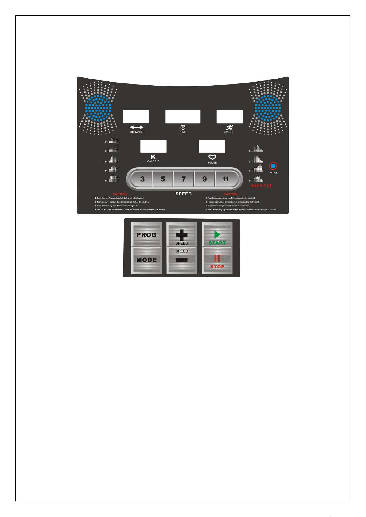
1.8. Manual Modes
1.8.1. How to enter manual mode:
A. Switch on the power supply; then, directly enter normal mode under the manual
mode.
B. In stop state, press MODE to select Normal mode, Time Countdown, Calorie
Countdown and Distance Countdown modes under the manual mode.
1.8.2. Setting functions under manual mode: Time, Distance and Calorie Setting
A. When entering the manual mode, the time is displayed as 0:00;
B. In manual mode, press MODE to enter Time Countdown mode; the time window
will display the time and flicker; the initial time is 30:00; set countdown time by
SPEED +/ SPEED. Time setting range: 5:00-99:00; each time of increase/ decrease
will be 1: 00.
C. In time countdown mode, press MODE to enter Distance Countdown mode; the
initial distance will be displayed as 1.00 km; set the distance by SPEED +/ SPEED -
in the range of 1.0-99.0 km; each time of increase/ decrease will be 1 km.
D. In distance countdown mode, press MODE to enter Calorie Countdown mode; the
initial distance will be displayed as 50.0kcal; set the calorie by SPEED +/ SPEED - in
the range of 20.0-990.0 kcal; each time of increase/ decrease will be 10.0 kcal.
1.8.3. Operation in manual mode:
A. Press START and the motor will start operating after 3s of countdown; the initial
speed will be 0.8km/h for metric system or 0.5mile/h for imperial system;
B. Press SPEED +/ SPEED - to adjust speed;
C. Press speed shortcuts to quickly set up to the speed marked on the key;
D. When the motor is running, press STOP and the motor will slow down and stop
finally;
E. Remove the safety lock to urgently stop motor running; then, LED window will
display “---” and the buzzer will make short sound of Bi-Bi-Bi.
F. When the set time reduces to zero or when the set calorie reduces to zero, or the set
distance reduces to zero, the speed will gradually reduce till the stop of the machine,
the buzzer will make short alarm “Bi-Bi-Bi”, and the speed window will display END;
5s later, the machine will return to the standby state and the buzzer will make long
alarm “Bi-Bi”;
G. Parameters not set will increase forwards, and will be reset after reaching the upper
limit of the display range; in manual mode, the machine will stop when the time
accumulates to be more than 99: 59 (100min).

- 12 -
1.9. Preset program
Each program is divided into 10 sections; the operation time will be evenly
distributed to each program section. Here below is the P1-P9 program running
diagrams.
Time section
Program
Set time / 10 = running time for each section
1
2
3
4
5
6
7
8
9
10
P1
SPEED
3
3
6
5
5
4
4
4
4
3
P2
SPEED
3
3
4
4
5
5
5
6
6
4
P3
SPEED
2
4
6
8
7
8
6
2
3
2
P4
SPEED
3
3
5
6
7
6
5
4
3
3
P5
SPEED
3
6
6
6
8
7
7
5
5
4
P6
SPEED
2
6
5
4
8
7
5
3
3
2
P7
SPEED
2
9
9
7
7
6
5
3
2
2
P8
SPEED
2
4
4
4
5
6
8
8
6
2
P9
SPEED
2
4
5
5
6
5
6
3
3
2
1.10. Body Fat Test:
In standby state, press PROG to enter FAT (Physical fitness test) program. Press
MODE to enter the program of F—1, F—2, F—3, F—4, F—5 (F—1:gender, F—2:age,
F—3:height, F—4:weight, F—5:physical test), Press SPEED +/ SPEED - to set the
parameter of 01-04(see below detailed table), then press MODE to enter the program of
F—5 for physical test. At this state, hold the handle pulse board for 5-6 seconds and it will
display the FAT, check if the weight matches with your height.
FAT is to measure the relevance between height and weight, not the body proportion.
FAT is suitable for every man and woman, it provide the important grounds for adjusting the
weight with other health indicators. The perfect FAT is between 20-24, which means if less
than 19 is too thin, and if between 25-29 is overweight and if more than 30 is obesity.
F--1
Gender
01(man)
02(woman)
F--2
Age
10------------99
F--3
Height
100----------200
F--4
Weight
20------------200
F--5
FAT
≦19
Underweight
FAT
=(20--24)
Normalweight
FAT
=(25--29)
Overweight
FAT
≧30
Obesity

- 13 -
1.11. Others
1.11.1 After the operation completion of a countdown parameter, END will be
displayed. The system will alarm for 0.5s at the interval of 2s until the steady stop of the
treadmill. Then, the system will return back to the manual mode.
1.11.2. Circular setting is supported for parameter setting. For example, the time
setting range is 5:00—99:00; to press “+” when the time displayed is 99:00, 5:00 will be
displayed, and so on. “+” and “-” can be used for increase and decrease.
1.11.3. Countdown time, countdown calorie and countdown distance can only be set
up for one of them. The last time setting will be implemented. The parameter set will be
counted backwards while other parameters will be counted forwards.
1.11.4. The standard calorie is 70.3kcal/km.
1.11.5. The acceleration is 0.5Km/S and the deceleration is 0.5Km/S.
1.11.6. MP3 audio play support amplification function. Input from the audit input hole
on the side.
1.11.7. The parameters accumulate in the course of using. It’s cleared when it’s to
maximum and then continue; It will stop when the time is accumulated more than
99:59 (100 minutes) in manual mode.

- 14 -
1.12. Meanings of error message codes
Error
code
Failure description
Solutions
E1
Communication
abnormality: abnormal
communication
between the controller
and the electronic
meter after powering on
Stop the controller to enter failure state. It can not be started up. The electronic meter
displays the error code and the buzzer sounds for 3 times.
Possible reasons: The communication between the controller and the electronic
meter is blocked; check each section of connection of the communication wires from
the electronic meter to the controller and ensure that all core wires are well
connected. Check whether wirings between the electronic meter and the controller
are damaged; if yes, replace the damaged wire.
E2
Explosion-proof
protection: abnormal
power voltage or motor
abnormality leads to the
damage of driving
motor circuit
Stop and enter the failure state. The electronic meter buzzer sounds for 9 times and
the error code is displayed. No display at other areas. If recovering to the normal
state and enter into the standby state after stop, normal startup can be implemented.
Possible reasons: Check whether the power supply voltage is less than 50% of the
normal value; please ensure correct voltage and test again; check whether the
controller emits the odor of burning; if yes, replace the controller; check whether
motor wires are well connected; re-connect motor wires.
E3
Motor wirings are not
well connected
Stop and enter the failure state. The electronic meter buzzer sounds for 9 times and
the error code is displayed. No display at other areas. If recovering to the normal
state and enter into the standby state after stop, normal startup can be implemented.
Possible reasons: Check whether motor wires are well connected; re-connect
motor wires. Check whether the controller emits abnormal odor; replace it if yes.
No speed sensor
signal: while there is
voltage output from the
controller to the DC
motor, speed feedback
can not be received
from the motor for more
than 3s.
Stop and enter the failure state. The electronic meter buzzer sounds for 9 times and
the error code is displayed. No display at other areas. If the system enters into
standby state after about 10s of failure state, restart can be conducted.
Possible reasons: If speed sensor signal is not received for more than 3s, check
whether the sensor connector is well plugged or whether it is damaged; plug it well or
replace the sensor.
E5
Over-current protection:
in the operation state,
the controller
continuously detects
DC motor current of
more than the value of
rated current + 6A for
more than 3s.
Stop and enter the failure state. The electronic meter buzzer sounds for 9 times and
the error code is displayed. No display at other areas. If the system enters into
standby state after about 10s of failure state, restart can be conducted.
Possible reasons: System self-protection is triggered under excessive current
caused by the excessive load more than the rated value, or some place of the
treadmill is jammed so that the motor can not rotate; thus, the system start up
self-protection against excessive current under excessive load; adjust the treadmill
and restart it. Besides, check whether there is over-current sound or burning odor
when the motor is running; replace the motor; check whether the controller emits
abnormal odor; replace it if yes; check whether power supply voltage specifications is
inconsistent or too low and use correct voltage specifications for re-test.

- 15 -
EXERCISE INSTRUCTIONS
1. The Warm Up Phase
This stage helps get the blood flowing around the body and the muscles working properly. It
will also reduce the risk of cramp and muscle injury. It is advisable to do a few stretching
exercises as shown below. Each stretch should be held for approximately 30 seconds, do not
force or jerk your muscles into a stretch - if it hurts, STOP.
2. The Exercise Phase
This is the stage where you put the effort in.After regular use , the muscles in your legs will
become Stronger. Work to your but it is very important to maintain a steady tempo throughout.
The rate of work should be sufficient to raise your heart beat into the target zone shown on the
graph below.
This stage should last for a minimum of 12 minutes though most people start at about 15-20
minutes
3. The Cool Down Phase
This stage is to let your Cardio-vascular System and muscles wind down. This is a repeat
of the warm up exercise e.g. reduce your tempo, continue for approximately 5 minutes. The
stretching exercises should now be repeated, again remembering not to force or jerk your
muscles into the stretch.
As you get fitter you may need to train longer and harder. It is advisable to train at least three
times a week, and if possible space your workouts evenly throughout the week.
To tone muscle while on your Treadmill you will need to have the resistance set quite high.
This will put more strain on our leg muscles and may mean you cannot train for as long as you
would like. If you are also trying to improve your fitness you need to alter your training program.
You should train as normal during the warm up and cool down phases, but towards the end of
the exercise phase you should increase resistance, making your legs work harden than normal.
You may have to reduce your speed to keep your heart rate in the target zone.
The important factor here is the amount of effort you put in. The harder and longer you work the
more calories you will burn. Effectively this is the same as if you were training to improve your
fitness, the difference is the goal.

- 16 -
MAINTENANCE INSTRUCTIONS
WALKING BELT TENSION ADJUSTMENT AND CENTERING
DO NOT OVERTIGHTEN the walking belt. This may cause reduced motor performance and
excessive roller wear.
TO CENTER WALKING BELT
● Place treadmill on a level surface
● Run treadmill at approximately 3.5 mph
●If the running belt is too far to the right side, use the supplied Allen wrench to turn the right tension bolt
clockwise slowly, noticing the change of the deviating distance until the belt remains centered during
use. (Attention: the space between the belt and the right/left edgings is at a distance normally. And the
gap between the right and left distance should be no more than 5mm.)
●If the running belt is too far to the left side, turn the left tension bolt clockwise slowly, noticing the
change of the deviating distance until the belt remains centered during use. (Attention: the space
between the belt and the right/left edgings is at a distance normally. And the gap between the right and
left distance should be no more than 5mm.)
IF THE BELT IS TOO FAR TO THE RIGHT SIDE IF THE BELT IS TOO FAR TO THE LEFT SIDE
TENSIONING THE BELT
If you can feel a slipping sensation when running on the treadmill, the running belt must be tightened.
In most cases, the belt has stretched from use, causing the belt to slip. This is a normal and common
adjustment. To eliminate this slipping, tension both the rear roller bolts with the appropriate size allen
wrench, turning it 1/4 TURN to the right as shown. Try the treadmill again to check for slipping.
Repeat if necessary, but NEVER TURN the roller bolts more than 1/4 turn at a time. The belt
tension is set properly when the running belt is 50 - 75mm from the deck.
PIC B
PIC A

- 17 -
WARNING: ALWAYS UNPLUG THE TREADMILL FROM THE ELECTRICAL OUTLET BEFORE
CLEANING OR SERVICING THE UNIT.
CLEANING
General cleaning or the unit will greatly prolong the treadmill. Keep treadmill clean by dusting regularly.
Be sure to clean the exposed part of the deck on either side of the walking belt and also the side rails.
This reduces the build up of foreign material underneath the walking belt.
The top of the belt may be cleaned with a wet, soapy cloth. Be careful to keep liquid away from inside the
motorized treadmill frame or from underneath the belt. Warning:Always unplug the treadmill from the
electrical outlet before removing the motor cover. At least once a year remove the motor cover and
vacuum under the motor cover.
WALKING BELT AND DECK LUBRICATION
This treadmill is equipped with a pre-lubricated, low maintenance deck system. The belt/ deck friction
may play a major role in the function and life of your treadmill, thus requiring periodic lubrication. We
recommend a periodic inspection of the deck.
We recommend lubrication of the deck according to the following timetable:
Light user (less than 3 hours/ week) annually
Medium user (3-5 hours/ week) every six months
Heavy user (more than 5 hours/ week) every three months

- 18 -
EXPLODED DRAWING

- 19 -
PARTS LIST
Part No.
Description
Qty
Part No.
Description
Qty
1
Main frame
1
39
Moving roller
2
2
Left upright tube
1
40
Flat pad
4
3
Right upright tube
1
41
Cross Tapping Screw ST4*16
4
4
Bottom frame
1
42
Power wire
1
5
Running belt
1
43
Allen bolt M10*30
2
6
Running board
1
44
Washer Φ10*1.2
2
7
Hex socket Screw M6*25
4
45
Allen bolt M8*15
14
8
Nylon nut M6
4
46
Optical detector
1
9
Side rail
2
47
Screw ST2.3*8
2
10
Cushion
2
48
Computer lower wire
1
11
Motor Belt
1
49
Computer middle wire
1
12
Adjustable plug
2
50
Computer upper wire
1
13
Cross Screw ST4*12
34
51
Safety lock sensor
1
14 L/R
Roller End cap
1 pr.
52
Screw ST3*9.5
14
15
Bolt M6*55
2
53
Safety lock iron slice
1
16
Rear roller
1
54
Safety lock
1
17
Adjustable pad
2
55
Shortcut key
2
18
Washer Φ8*1.2
12
56
Computer frame
1
19
Allen bolt M8*45
2
57
Foam grip
2
20
Nylon nut M8
2
58
Computer cover
1
21
Protective guard
1
59
Computer rear cover
1
22
Screw M4*8
3
60
Bottle case
2
23
On/off Switch
1
61 L/R
Base cover
1 pr.
24
Power wire buckle
1
62
Computer board
1
25
Screw M6*45
1
63
Screw ST4*12
2
26
Front roller
1
64
Bracket
1
27
Allen bolt M8*40
3
65
Rubber gasket
4
28
Shock
1
66
Circuit board
1
29
Allen bolt M8*25
1
67
Circuit board wire
1
30
Motor cover
1
68
Loudspeaker (optional)
2
31
Screw M5*8
4
69
Choke (optional)
1
32
Motor
1
70
EMC Filter (optional)
1
33
Hex bolt M8*50
1
71
Screw (optional)
4
34
Screw M8*35
2
72
MP3 cable (optional)
1
35
Screw M8*15
4
73
Audio socket (optional)
1
36
Spring washer D8
6
74
USB/Sd card socket (optional)
1
37
Flat washer D8
6
75
Amplifier board (optional)
1
38
Cap
2
76
Circuit breaker
1
Table of contents
Other VIVA FITNESS Treadmill manuals

VIVA FITNESS
VIVA FITNESS T470 User manual

VIVA FITNESS
VIVA FITNESS T145 User manual

VIVA FITNESS
VIVA FITNESS T909 User manual

VIVA FITNESS
VIVA FITNESS T240 User manual

VIVA FITNESS
VIVA FITNESS T1919 User manual

VIVA FITNESS
VIVA FITNESS T146 User manual

VIVA FITNESS
VIVA FITNESS T752 User manual

VIVA FITNESS
VIVA FITNESS T99 User manual

VIVA FITNESS
VIVA FITNESS T245 User manual

VIVA FITNESS
VIVA FITNESS T255 User manual