Instruction Manual PMC-24V150W1BL
www.DeltaPSU.com
1. Safety Instructions
• Toensuresufcientconvectioncooling,alwaysmaintainasafetydistanceof
≥20mmfromallventilatedsurfaceswhilethedeviceisinoperation.
• The device is not recommended to be placed on low thermal conductive
surface,forexample,plastics.
• Notethattheenclosureofthedevicecanbecomeveryhotdependingonthe
ambienttemperature andloadofthepowersupply.Donot touchthedevice
whileitisinoperationorimmediatelyafterpoweristurnedOFF.Riskofburning!
• Donottouchtheterminalswhilepowerisbeingsupplied.Riskofelectricshock.
• Preventanyforeignmetal,particlesorconductorstoenterthedevicethrough
theopeningsduringinstallation.Itcancause:Electricshock;SafetyHazard;
Fire;Productfailure
• Warning: When connecting the device, secure Earth connection before
connecting L and N. When disconnecting the device, remove L and N
connectionsbeforeremovingtheEarthconnection.
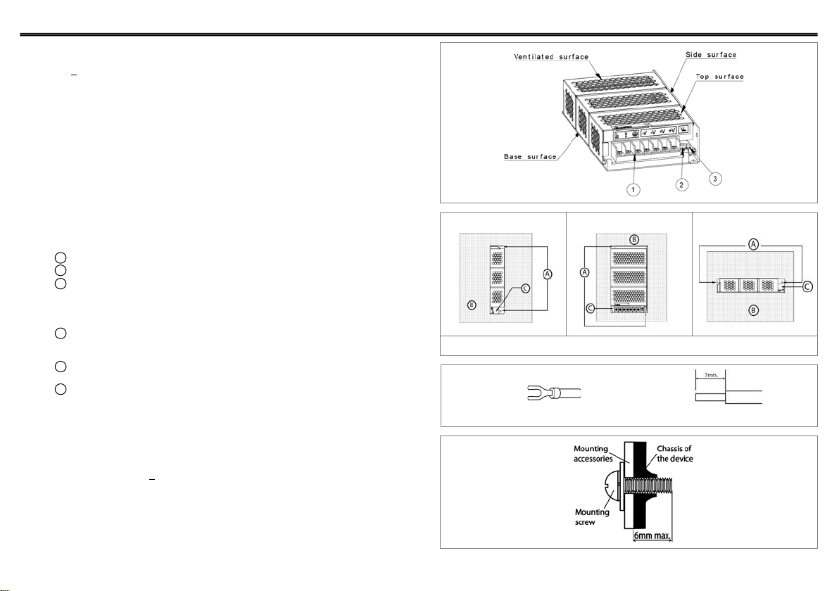
2. Device Descriptions
RefertoFig.1.:
䐟Input&Outputterminalblockconnector
䐠DCvoltageadjustmentpotentiometer
䐡DCOKcontrolLED(Green)
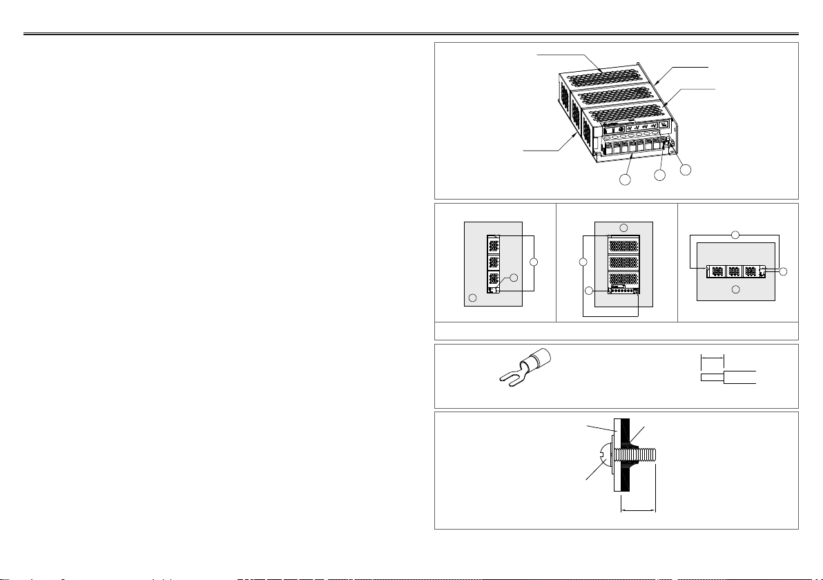
3. Installation of the Device
RefertoFig.2.:
䑵Mounting holes for power supply assembly onto the mounting surface. The
powersupplyshallbemountedonminimum2mountingholesusingM3screw
minimum5mmlength.
䑶This surface belongs to customer’s end system or panel where the power
supplyismounted.
䑷Connector
• Use exible cable (stranded or solid), AWG No. 18-14. The torque at the
Connectorshallnoexceed13Kgf.cm.Theinsulationstrippinglengthshould
notexceed0.275”or7mm(RefertoFig.3).
4. Installation of Mounting Accessories
RefertoFig.4.:
• OnlyuseM3screw≤6mmthroughthebasemountingholes.Thisistokeepa
safetydistancebetweenthescrewandinternalcomponents.
• Recommendedmountingtighteningtorque:4~8Kgf.cm.
Fig. 1. Device Descriptions
Fig. 2. Mounting Orientation
Side Mounting (Vertical) Base Mounting (Vertical) Side Mounting (Horizontal)
REV.00
Fig. 3. Wire Type
Fig. 4. Mounting Screw
Lug Stripped wire
7mm.
A
B
C
Mounting
accessories
Mounting
screw
Chassis of
the device
6mm max.
A
C
B
A
B
C
123
Base surface
Top surface
Side surface
Ventilated surface