USR IOT USR-W630 User manual

USR-W630 User Manual Technical Support: h.usriot.com
Jinan USR IOT Technology Limited 2
Contents
USR-W630 User Manual............................................................................................................................................ 1
1. Get Start................................................................................................................................................................ 4
1.1. Hardware Connection.......................................................................................................................... 4
1.2. Net Connection.....................................................................................................................................4
1.3. Data Transmission Test.........................................................................................................................6
2. Product Overview.................................................................................................................................................7
2.1. Product Introduction............................................................................................................................7
2.2. Product Feature.................................................................................................................................... 7
2.3. Electrical Parameters............................................................................................................................8
2.4. Product Appearance.............................................................................................................................9
2.5. Work Indicator Lamp............................................................................................................................9
2.6. Interface Specification....................................................................................................................... 10
2.7. Appearance Size................................................................................................................................. 10
2.8. Application Area.................................................................................................................................11
3. Product Networking Application....................................................................................................................... 11
3.1. Work as AP..........................................................................................................................................12
3.2. Work as STA........................................................................................................................................ 12
3.3. Work as AP+STA..................................................................................................................................12
3.4. Wireless Serial Port Application........................................................................................................ 13
3.5. Network Cable Bridge Application (AP)............................................................................................ 14
3.6. Wireless Bridging Application(AP+STA).............................................................................................15
3.7. Application of wireless plus cable..................................................................................................... 16
4. Product Function................................................................................................................................................ 17
4.1. Work Mode.........................................................................................................................................17
4.1.1. Transparent Transmission Mode............................................................................................... 17
4.1.2. Serial Port Command Mode...................................................................................................... 17
4.1.3. HTTPD Client Mode.................................................................................................................... 17
4.1.4. MODBUS TCPMODBUS RTU.................................................................................................. 17
4.1.5. AT Commands Mode.................................................................................................................. 17
4.2. Wireless Characteristics..................................................................................................................... 18
4.2.1. Auto Frequency Selection Function.......................................................................................... 18
4.2.2. Security Mechanism...................................................................................................................18
4.2.3. STA Join The Router....................................................................................................................18
4.3. Socket Communication...................................................................................................................... 18
4.4. UART Framing Mechanism.................................................................................................................18
4.4.1. UART Free Framing Mode.......................................................................................................... 18
4.4.2. UART Auto Framing Mode......................................................................................................... 19
4.5. Password Authentication When TCP Establishing Connection........................................................19
4.6. Register MAC/CLOUD/USR Function.................................................................................................19
4.7. Class RFC2217 Automatic Baud Rate Function................................................................................. 20
4.8. Keep-alive Function............................................................................................................................21
4.9. USR-Link..............................................................................................................................................21

USR-W630 User Manual Technical Support: h.usriot.com
Jinan USR IOT Technology Limited 3
4.10. Search in LAN......................................................................................................................................22
4.11. Custom Heartbeat Package................................................................................................................23
4.12. Socket Function.................................................................................................................................. 23
4.13. Timeout Restart Function.................................................................................................................. 24
4.14. Timer Restart Function.......................................................................................................................25
4.15. Modbus Polling...................................................................................................................................25
4.16. Remote Upgrade.................................................................................................................................25
4.17. Firmware Upgrade..............................................................................................................................25
5. Setting Method...................................................................................................................................................27
5.1. Webpage Setting................................................................................................................................ 27
5.1.1. Open The Webpage....................................................................................................................27
5.1.2. Quick Configuration................................................................................................................... 28
5.1.3. Other Page.................................................................................................................................. 29
5.2. AT Command Setting..........................................................................................................................29
5.2.1. Serial Port AT Commands...........................................................................................................29
5.2.2. Net AT Commands......................................................................................................................29
5.3. AT Commands.....................................................................................................................................29
6.Contact Us................................................................................................................................................................32
7.Disclaimer................................................................................................................................................................ 33
8.Update History.........................................................................................................................................................34

USR-W630 User Manual Technical Support: h.usriot.com
Jinan USR IOT Technology Limited www.usriot.com
4
1. Get Start
This chapter is a quick introduction to the USR-W630 product. New users are advised to read this chapter carefully
and follow instructions to get a systematic understanding of the product. Users can skip this chapter if they are
familiar with such products. Refer to the subsequent chapters for specific details and instructions.
1.1. Hardware Connection
We connect the serial port and network port of the USR-W630 to PC, if your PC have no serial port, you can use USB
to 232 line. Hardware connection:
Figure 1 hardware connection
You just need connect 232 line and power to W630 as picture shows.
1.2. Net Connection
Search WIFI on PC, connect the WIFI named USR-W630-xxxx( xxxx means the last 4 bit of MAC address )

USR-W630 User Manual Technical Support: h.usriot.com
Jinan USR IOT Technology Limited www.usriot.com
6
Figure 3 connect to the wifi of W630
Link indicator light will light up when PC join the wifi of W630.
1.3. Data Transmission Test
The default encryption mode of W610:open, none
The default serial port parameters:57600,8,1,None
The default network parameters: TCP,Server,8899,10.10.100.254
Steps of testing
1\open”USR-TCP232-Test.exe”, COM11 represents the serial number of W610,set the baud rate 57600,then open the
serial port;
2\choose TCP Client mode, IP:10.10.100.254,the server port is 8899,then click connect.
The data from serial port to net is: serial port of PC->serial port of W630->W630->network port(or wifi) of W630->PC;
The data from net to serial port is: PC-> network port(or wifi) of W630->W630->serial port of W630->serial port of PC

USR-W630 User Manual Technical Support: h.usriot.com
Jinan USR IOT Technology Limited www.usriot.com
7
Figure 4 data transmission test
Note: users need to turn off the redundant network cards, and only keep one WiFi connection.
2. Product Overview
2.1. Product Introduction
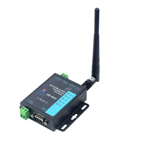
USR-W630 provide the function of serial port to WIFI, serial port to Ethernet, Ethernet to WIFI. It can send data from
RS232/485 serial port to TCP/IP network port, from RS232/485 serial port to WIFI/ Ethernet, vice versa. It can expand
the communication distance of serial devices.
2.2. Product Feature
It has positioning holes on the shell and is convenient for installation
Support remote upgrade, MODBUS polling
Standard configuration: power cord, serial cable and net cable. Easy to use
DC5-36V power in, 5.5*2.1 standard power interface and terminal
Status indicator lamp: Power, Work, Ready, Link, UART1, WAN/LAN, LAN
UART to WIFI core module
Support TCP Server/TCP Client/UDP Server/UDP Client work mode

USR-W630 User Manual Technical Support: h.usriot.com
Jinan USR IOT Technology Limited www.usriot.com
8
When work at TCP Server mode, it support up to 24 Client to connect
Support set baud rate, range: 300bps to 460800bps
Support set parameters on webpage
Support reload
The distance for transmission can be 210m
Ensure production quality
2.3. Electrical Parameters
Table 1 default parameters
Item
Index
Wireless parameters
Standard authentication
FCC/CE
Wireless standard
802.11 b/g/n
Frequency range
2.412GHz-2.48GHz
Transmitting power
802.11b: +20dBm(Max.)
802.11g: +18dBm(Max.)
802.11n: +15dBm(Max.)
User define
Receiving sensitivity
802.11b: -89dBm
802.11g: -81dBm
802.11n: -71dBm
Hardware parameters
Data interface
UART:300bps-460800bps
RS485(Surge prevention, lightning
protection, over-current
protection)
Enternet:10Mbps/100Mbps
Working voltage
DC5-36V
Working temperature
-20℃-70℃
Storage temperature
-40℃-125℃
Size
103*105*25mm(L*W*H)
Software parameters
Wireless network type
STA/AP mode
Security mechanism
WPA-PSK/WPA2-PSK
Encryption type
TKIP/AES
Working mode
Transparent transmission mode/
Serial port command mode/
Httpd Client mode/
Modbus mode
Setting command
AT+command
Network protocol
TCP/UDP/ARP/ICMP/DHCP/DNS/HT
TP
Max number of TCP connect
24
User setting
Web server+ AT commands

USR-W630 User Manual Technical Support: h.usriot.com
Jinan USR IOT Technology Limited www.usriot.com
9
Customized
Support
2.4. Product Appearance
Figure 5 USR-W630
2.5. Work Indicator Lamp
The module has 7 indicator lamp:
Table 2 work indicator lamp
Indicator lamp
Function
Instruction
Power
Power indication
Light on when use right power supply
Work
Work status indicator
Light flicker when system start
Ready
Start up indicator
Light on when system start up
Link
Net connection
Light on when wifi connect
UART1
COM 1 status indication
Blue light flicker when data transmission
from serial port to net port;
Red light flicker when data transmission
from net port to serial port
UART2
COM 2 status indication
Reserve
WAN/LAN
NET 1 connect/data
transmission
Light on when connect with WAN/LAN;
Flicker when send data
LAN
NET 2 connect/data
transmission
Light on when connect with LAN;
Flicker when send data

USR-W630 User Manual Technical Support: h.usriot.com
Jinan USR IOT Technology Limited www.usriot.com
10
2.6. Interface Specification
Antenna interface:
3dbi antenna
Power interface:
5.5*2.1 standard DC power interface, product power input with TVS protection
RS232 interface:
The serial port of device is male connector, RS232, the pin sequence is consistent with the COM port of the computer.
When connecting with the computer, we need to use crossing lines (2-3 crossing, 7-8 crossing, 5-5 direct connection,
7-8 can’t be connected, but must not be directly connected to the computer, otherwise it may lead to abnormal work),
a total of six wires are defined, the rest are suspended.
Table 3 the pin of RS232
2
RXD
Data received
3
TXD
Data send
5
GND
Grounding
7
RTS
Request to send
8
CTS
Clear send
9
VCC
Default not used
RS485 interface:
RS485 interface is A(data+),B(data-)and GND, when connect with RS485 device, A(+) to A(+),B(-)to B(-),GND to GND.
RJ45 net interface:
The interface of the WIFI dual-port serial port server is 10M/100M self-adapting and supports AUTO MDI/MDIX, that
is to say, it can be tested by direct connection with the computer. The serial port server opens the network port by
default.
Reload key:
This button can restore the factory settings. Press 3s or more when the device is in normal working state (after the
Ready light is on), wait for 8s for the W630 to start automatically (except the Power indicator, the other indicator lights
go out and then the Ready lights turn on), and restore the settings to the factory settings.
2.7. Appearance Size
Unit mm

USR-W630 User Manual Technical Support: h.usriot.com
Jinan USR IOT Technology Limited www.usriot.com
11
Figure 6 schematic diagram of interface
2.8. Application Area
Serial port (RS232/RS485) to WIFI/ Ethernet.
WIFI remote control / monitoring, TCP/IP and WIFI coprocessor;
WIFI remote control of aircraft, cars and other toys;
WIFI network radio, camera, digital photo frame;
Medical instruments, data acquisition and handheld devices.
WIFI fat scale, smart card terminal, home intelligence;
Instrument and equipment parameter monitoring, wireless POS;
Modern development of agriculture, military and other wireless related two development applications
3. Product Networking Application
The USR-W630 serial server can be configured either as a wireless STA or as an AP. So USR-W630 logically supports
two wireless interfaces, one as STA, the other as an AP, and the other STA can connect to the wireless network
through AP interface of the serial server.
At the same time, serial server provides a 100M Ethernet interface, through this Ethernet port , users can realize the
WIFI port, serial port, Ethernet port, three interfaces interoperability. In terms of networking, USR-W630 module
supports bridging mode and routing mode to correspond to different specific applications.
Therefore, USR-W630 can provide very flexible networking and network topology.
Description
AP: wireless access point, which is the core node of a wireless network. The wireless router is an AP, and other
wireless terminals can be connected to each other via AP.
STA: wireless station, which is a terminal of wireless network. Such as PC , PAD, etc.

USR-W630 User Manual Technical Support: h.usriot.com
Jinan USR IOT Technology Limited www.usriot.com
12
3.1. Work as AP
Set W630 work at AP mode. Other W630s and computers can be connected to the W630 as STA, and it can also be
connected to user equipment through RS232/RS485 interface.
Figure 7 work as an AP
3.2. Work as STA
Set W630 work at STA mode and connect to other AP. The communication between STA is accomplished by AP
forwarding.
Figure 8 work as STA
3.3. Work as AP+STA
USR-W630 can support one AP interface and one STA interface simultaneously. After opening the AP+STA function,
the STA and AP interfaces are available at the same time. The STA interface of the serial server is connected to the
router and is connected to the server in the network through TCPB, and the AP interface can be connected by mobile
phone / PAD (through TCPA). The TCP Server, mobile phone / PAD and so on in the network can control the serial port
devices connected by USR-W630 or set the parameters of serial port server itself.

USR-W630 User Manual Technical Support: h.usriot.com
Jinan USR IOT Technology Limited www.usriot.com
13
Figure 9 work as AP+STA
Through the AP + STA function, it is easy to use handheld devices such as mobile phone / PAD to monitor user
equipment without changing its original network settings.
Through the AP + STA function, the serial port server can be set conveniently, which solves the problem that the
serial port server can only be set through the serial port in STA.
3.4. Wireless Serial Port Application
USR-W630's wireless can be configured either as a wireless STA or as an AP. Logically, two wireless interfaces are
supported, one as STA and the other as an AP. The other STAs can be connected to the wireless network through the
AP interface of the W630.
Figure 10 wirless serial port application

USR-W630 User Manual Technical Support: h.usriot.com
Jinan USR IOT Technology Limited www.usriot.com
14
3.5. Network Cable Bridge Application (AP)
Figure 11 application of network cable bridge
Set USR-W630 work at AP mode, turn off the DHCP server of the module, and the IP is modified to a same network
segment with the router (the "Wireless Access Point Settings" page in the web page has the corresponding options),
and the ports 1 and 2 are set to LAN ports. After setting up, the network port 2 connects to the router, and the
network port 1 connects to the computer. In this way, computers, serial servers and routers are in the same network
segment. The serial server is equivalent to a switch bridge connected to routers and computers.
Table 4 AT commands
No.
Command
Intro
1
AT+WAP
Set the SSID of router
2
AT+WAKEY
Set the password of router
3
AT+LANN
Set the IP of W630 in the same network segment with
the router
4
AT+DHCPDEN=off
Enable the DHCP function of W630

USR-W630 User Manual Technical Support: h.usriot.com
Jinan USR IOT Technology Limited www.usriot.com
15
3.6. Wireless Bridging Application(AP+STA)
Figure 12 wireless bridging application
USR-W630 work as AP+STA, the SSID and encryption, encryption algorithm (the "wireless access point settings"
section of the Web page) of AP set to the same parameters as STA (the "wireless terminal settings" in the Web page),
and STA to connect to the router (the IP of AP in the same network segment with router). In this way, the wireless
dual-port serial port server is equivalent to a wireless switch bridging to the router, which expands the wireless
coverage of the router.
Table 5 AT commands
No.
Command
Intro
1
AT+FAPSTA=on
Enable AT+STA mode, the command is restored to the
factory settings valid.
2
AT+FVER=z
Enable Z mode, the command is restored to the factory
settings valid.
3
AT+WMODE=STA
Set W630 work at STA mode
4
AT+WSSSID
Set the SSID of router which W630 join
5
AT+WSKEY
Set the password of router which W630 join
6
AT+WAP
Set the SSID of router
7
AT+WAKEY
Set the password of router
8
AT+LANN
Set the IP of W630 in the same network segment with
router
9
AT+DHCPDEN=off
Unable the DHCP function of W630

USR-W630 User Manual Technical Support: h.usriot.com
Jinan USR IOT Technology Limited www.usriot.com
16
3.7. Application of wireless plus cable
Figure 13 application 1 of wireless plus cable
When W630 work at AP mode, the STA can connect by RJ45 or WI-FI to W630
Figure 14 application 2 of wireless plus cable
When W630 work at STA mode, it can connect PC with RJ45, or join the WI-FI of AP.
Figure 15 application 3 of wireless plus cable
When W630 work as AP , it can connect external network with RJ45, other PC or device connect to W630 through
WI-FI.

USR-W630 User Manual Technical Support: h.usriot.com
Jinan USR IOT Technology Limited www.usriot.com
17
4. Product Function
4.1. Work Mode
W630 work mode: transparent transmission mode, serial port command mode, HTTPD Client mode, MODBUS mode,
AT command mode.
4.1.1. Transparent Transmission Mode
W630 supports the serial port transparent transmission mode, in which the data needed to be sent and received are
transparently transmitted between the serial port and WIFI / Ethernet, without any parsing, to achieve data transfer
between general serial port devices and network devices.
In transparent transmission mode, users can fully compatible with the original software platform. Users can basically
support wireless data transmission without software modification.
4.1.2. Serial Port Command Mode
In this mode, when the USR-W630 serial server acts as UDP Client or TCP Client, the user is allowed to send serial data
to different servers.
Customer MCU send packets in the following format. After the server parses the WIFI string, only n bytes of data are
sent to the destination address. When data is returned, the data is output from the serial port without parsing.
4.1.3. HTTPD Client Mode
In this mode, the user can send data to the specified HTTP server, and the W630 automatically adds HTTP protocol
header to the data sent, the content of the specific protocol header can be set by AT instructions or web pages.
This mode is used by W630 transmit data to HTTP server or to retrieve data from HTTP server. Users are using the AT
commands or webpage to set up the specific contents of the HTTP header.W630 automatically encapsulates the sent
data into HTTP protocol data and sends it to the designated HTTP server. The data received from the server will be
directly transmitted to the serial port without any processing. The tedious HTTP protocol is done by the WIFI serial
port server, which is convenient for the user to program the serial port without considering too much HTTP.
4.1.4. MODBUS TCP
MODBUS RTU
Support Modbus TCP to Modbus RTU(not support Modbus ASCII), the net parameter of module should be
Corresponding with the software, TCP server to the TCP client, port to the configuration to the same, work mode is
Modbus TCP<=>Modbus RTU.
4.1.5. AT Commands Mode
In AT commands mode, users can query the current state of USR-W630 or set the parameters of USR-W630 by sending
AT commands.

USR-W630 User Manual Technical Support: h.usriot.com
Jinan USR IOT Technology Limited www.usriot.com
18
4.2. Wireless Characteristics
4.2.1. Auto Frequency Selection Function
When W630 work in STA mode, the WIFI serial port server will adjust itself to the same channel as AP according to the
wireless channel of AP and access it.
When W630 work in AP mode, it can be set to automatic frequency selection mode, so when the W630 starts, it will
choose a better wireless channel according to the surrounding environment.
4.2.2. Security Mechanism
USR-W630 supports a variety of wireless network encryption methods, which can fully guarantee the safe
transmission of data, including:
WPA-PSK/TKIP
WPA-PSK/AES
WPA2-PSK/TKIP
WPA2-PSK/AES
Note: the WPA-PSK and WPA2-PSK passwords are at least 8 bits.
4.2.3. STA Join The Router
The search button is added to the W630 wireless terminal settings page. When you click the button, a window will
pop up to display the surrounding AP information. After selecting the router, you will return to the original page. At
this time, the encryption mode and encryption algorithm have been filled in. You just need to write the password
according to the prompt.
4.3. Socket Communication
The USR-W630 has two Socket: Socket A and Socket B. Data written to the USR-W630 serial port, USR-W630 will
automatically send to Socket A and B at the same time; data received by USR-W630 through Socket A or Socket B, are
sent through the serial port.
Socket A works include: TCP Server, TCP Client, UDP Server, UDP Client. At present, Socket B supports TCP client and
UDP client (users can connect Socket B to remote server to realize remote control of equipment). Through the
different settings of dual Socket, multiple network interconnection modes can be realized.
When Socket A work at TCP Server, up to 24 TCP Client can be supported.
4.4. UART Framing Mechanism
4.4.1. UART Free Framing Mode
When receiving data from UART, the W630 constantly checks the interval between two adjacent bytes. If the interval
is longer than a certain value, a frame is considered end, otherwise the data is received until it is greater than 4K bytes.

USR-W630 User Manual Technical Support: h.usriot.com
Jinan USR IOT Technology Limited www.usriot.com
19
W630 determines that after the end of a serial port, it will be forwarded to the WIFI interface.
The default 2-byte interval of the W630 is 50 ms, when the interval is greater than 50 ms, one frame ends.
4.4.2. UART Auto Framing Mode
For fixed-length data frames on the serial port, UART auto-framing can be turned on to achieve the highest forwarding
efficiency. USR-W630 serial port server supports UART port auto framing function. After setting the trigger time and
the trigger frame length, the serial server will automatically frame the data received from the serial port and forward
it to the network.
4.5. Password Authentication When TCP Establishing Connection
This function is only applicable to W630 work as TCP Server. When TCP Client connects to W630, W630 authenticates
each connected TCP.
The first data sent after TCP Client is connected should be the web page password of the W630 plus carriage return.
By default, the password of the W630 is admin, so the first data sent by the TCP Client should be "0x610x640x6D
0x690x6E 0x0D 0x0A" (hexadecimal). If the password is correct, the W630 returns "OK" instead of "NO" and
disconnects.
This function can be opened or disabled in the "TCP connection password verification" on the web page.
4.6. Register MAC/CLOUD/USR Function
This function is only applicable when W630 work at TCP Client.
The registration USR-CLOUD function is that when W630 connects to the server, it sends the registration package
composed of device ID and communication password. The registration package information is correct, the server
returns the registration success information, and the W630 accesses the USR-CLOUD platform.
The registration USR (user-defined registration package) feature allows users to customize the content of the
registration package, and the length is limited to less than 40 characters (UDP Client supported, adding user-defined
registration packages before sent the data).
There are two ways to register the MAC / USR function: one is to send the registration information when connecting
to the server for the first time, and the other is to add the registration information to the data sent each time.
There is only one way to register a CLOUD, that is, to send a registry package to join USR-Cloud when connecting to a
server.
Figure 16 send registration package when connect

USR-W630 User Manual Technical Support: h.usriot.com
Jinan USR IOT Technology Limited www.usriot.com
20
Figure 17 send registration package with data
The relevant parameters of the function are set on the "serial port and other settings" part of the web page, and the
default is closed.
The relevant commands are set as follows:
Table 6 AT commands
No.
Command
Intro
1
REGEN
Setting the type of registration package
2
REGTCP
Registration package settings
3
REGCLOUD
Query/setting USR-Cloud account and password
4
REGUSR
Query/setting USR-Cloud custom registration package content
4.7. Class RFC2217 Automatic Baud Rate Function
RFC2217 is a standard protocol for instantly modifying device serial port parameters through Ethernet. This device
supports a protocol similar to RFC2217, not standard RFC2217, which implements the same function, but the protocol
is simpler.
Table of contents
Other USR IOT Media Converter manuals

USR IOT
USR IOT USR-TCP232-306 User manual

USR IOT
USR IOT USR-DR404 User manual

USR IOT
USR IOT USR-N520 User manual

USR IOT
USR IOT USR-TCP232-302 User manual

USR IOT
USR IOT USR-TCP232-410s User manual

USR IOT
USR IOT USR-TCP232-ED2 User manual

USR IOT
USR IOT USR-N540 User manual

USR IOT
USR IOT USR-CANET200 User manual

USR IOT
USR IOT USR-TCP232-E2 User manual

USR IOT
USR IOT USR-GM1 User manual