Vivid CLV-403 User manual

CLV-403 CAMERA LINK VIDEO SPLITTER
User’s Manual
Document # 200595, Rev 1.0, 5/6/2009
Vivid Engineering
418 Boston Turnpike #104 • Shrewsbury, MA 01545
Phone 508.842.0165 • Fax 508.842.8930

Table of Contents
1. Introduction 1
1.1. Overview 1
1.2. Features 3
1.3. Functional Description 4
1.4. Typical Applications 6
1.4.1. Standard Base Application 6
1.5. Specifications 7
2. Interface 8
2.1. Front Panel Connections 8
2.2. Rear Panel Connections 9
2.3. Camera Connector Signals 10
2.3.1. Cable Shield Grounding 10
3. Mechanical 12
3.1. Dimensions 12
3.2. External Power Supply 13
4. Regulatory Compliance 14
4.1. FCC Compliance Statement 14
4.2. Canadian Compliance Statement 14
5. Revision History 15

1
1. Introduction
1.1. Overview
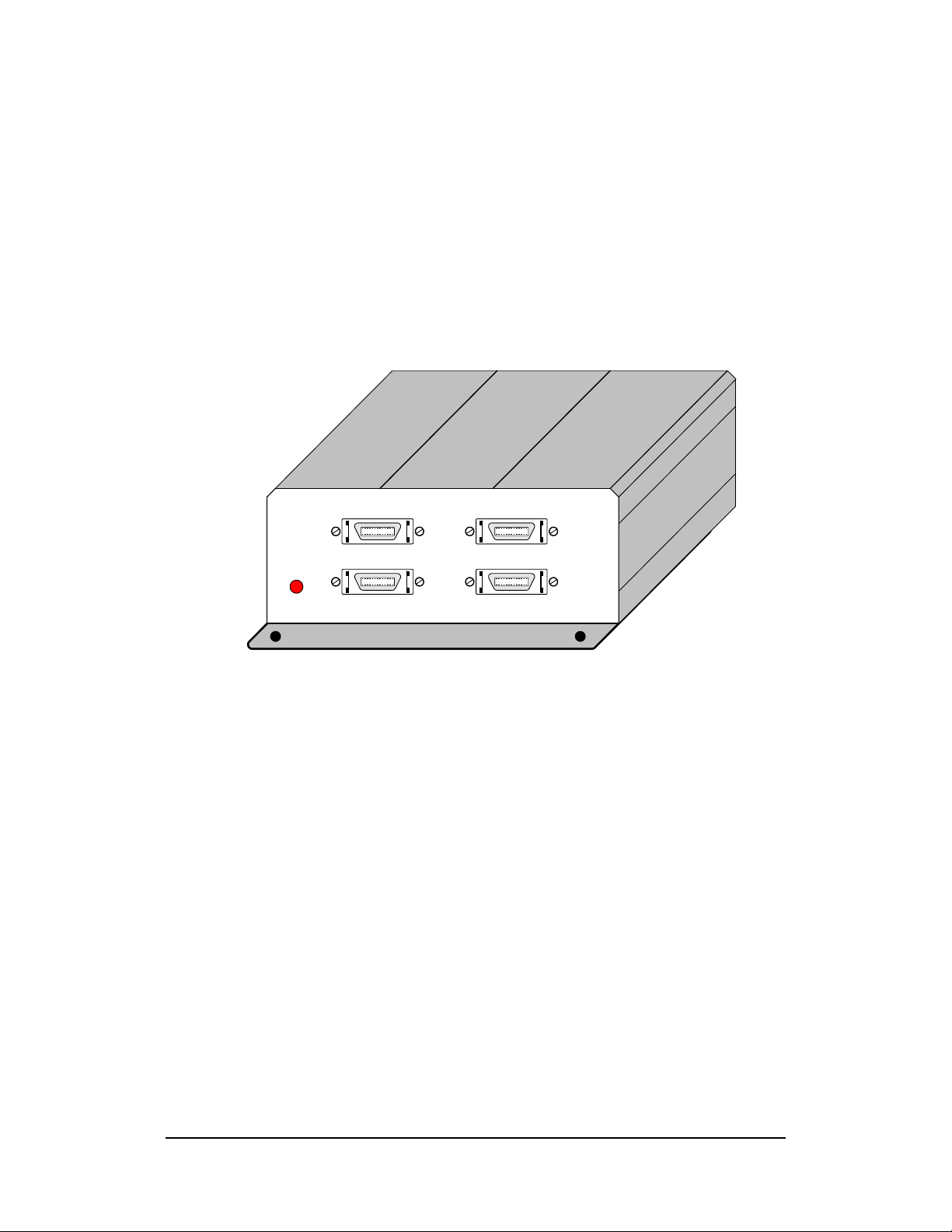
Designed for multi-camera systems, the CLV-403 Camera Link1Video Splitter interfaces
two Camera Link cameras to two frame grabbers each using standard Camera Link cables.
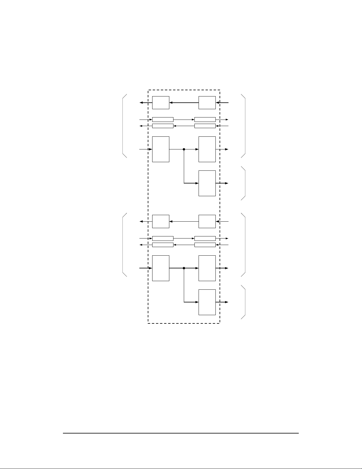
This enables the use of secondary frame grabbers for applications requiring parallel or
distributed processing, monitoring, etc. One frame grabber acts as master and provides
control and communications to the camera. The second frame grabber receives camera
video data only.
The CLV-403 incorporates high-speed 85 MHz interfaces and supports Camera Link base
configuration cameras. The CLV-403 also acts as a repeater, doubling the maximum
distance between the cameras and the frame grabbers.
Housed in a sturdy, compact aluminum enclosure, the CLV-403 Camera Link Video
Splitter is well suited for industrial environments.
1The Camera LinkTM interface standard enables the interoperability of cameras and frame grabbers,
regardless of vendor. The Automated Imaging Association (AIA) sponsors the Camera LinkTM
program including the oversight Camera Link Committee, the self-certification program, and the
product registry. The Camera LinkTM specification may be downloaded from the AIA website,
found at www.machinevisiononline.org
Camera LinkTM is a trademark of the Automated Imaging Association

2
Camera Link Video
Splitter CLV-403
V
ivid
E
ngineering
B
CAMERAS
AA
B
MASTER FRAME GRABBERS

3
1.2. Features
•Two independent splitters in a single unit for multi-camera systems
•Supports secondary frame grabbers for parallel processing, monitoring, etc
•Uses standard Camera Link cables (not included)
•Supports Camera Link Base configuration
•High-speed 85 MHz interface chipset
•Also acts as a repeater, doubling max distance between the cameras and the frame
grabbers
•Sturdy, compact aluminum enclosure w/ mounting flange
•Universal power supply included
•3-year warrantee

4
1.3. Functional Description
A block diagram of the CLV-403 Camera Link Video Splitter is provided in Figure 1-1.
The CLV-403 features two independent base-configuration splitters in a single unit for
multi-camera systems.
Each splitter interfaces one camera to two frame grabbers using standard Camera Link
cables. One frame grabber is the master (primary), and one frame grabber is slave
(secondary).
The interface between the camera and the master frame grabber contains the entire
Camera Link signal set defined in the Camera Link Specification for “base”
configurations. This consists of video data, camera control, and serial communications.
The master frame grabber receives video data from the camera, and can also control and
communicate with the camera.
The interface between the camera and the slave frame grabber contains only the video data
signals. The slave frame grabber receives video data, but cannot control or communicate
with the camera.
Since the CLV-403 regenerates all signals, it also acts as a repeater and supports an
additional 10 meters of separation between the cameras and the frame grabbers.
The CLV-403 is powered by an external wall plug-in power supply.

5
Channel
Link
Receiver
Channel
Link
Transmitter
LVDS
Receiver
LVDS
Transmitter
LVDS Rcvr
To Camera Link Camera "B"
Video
Data
Camera
Control
Serial
Comm
Link LVDS Xmtr
LVDS Xmtr
LVDS Rcvr
Video
Data
Camera
Control
Serial
Comm
Link
To Camera Link
Frame Grabber "B" (Master)
CLV-403 Camera Link Video Splitter
Channel
Link
Transmitter
Video
Data
To Camera Link
Frame Grabber "B" (Slave)
Channel
Link
Receiver
Channel
Link
Transmitter
LVDS
Receiver
LVDS
Transmitter
LVDS Rcvr
To Camera Link Camera "A"
Video
Data
Camera
Control
Serial
Comm
Link LVDS Xmtr
LVDS Xmtr
LVDS Rcvr
Video
Data
Camera
Control
Serial
Comm
Link
To Camera Link
Frame Grabber "A" (Master)
Channel
Link
Transmitter
Video
Data
To Camera Link
Frame Grabber "A" (Slave)
Figure 1-1: CLV-403 Block Diagram

6
1.4. Typical Applications
1.4.1. Standard Base Application
A typical CLV-403 base application is shown in Figure 1-2. Two independent
Camera Link base configuration cameras are connected to a single CLV-403 via
standard Camera Link cables. Additional Camera Link cables are then used to
connect the CLV-403 to master and a slave frame grabbers for each camera.
The master frame grabbers provide camera control and communications, and may
also perform processing functions. The slave frame grabbers cannot control or
communicate with the cameras, but may be used for parallel processing, secondary
processing, camera setup, monitoring, etc.
Camera Link Video
Splitter CLV-403
V
ivid
E
ngineering
B
CAMERAS
AA
B
MASTER FR AME GRABBERS
Camera Link
Cameras
Master
Camera Link
Frame Grabbers
CLV-403
Camera Link
Video Splitter
Standard Camera Link Cables
Slave
Camera Link
Frame Grabbers
B
A
A
B
B
A
Figure 1-2: CLV-403 Standard Application (Base)

7
1.5. Specifications
Table 1-1: CLV-403 Specifications
Feature
Specification
Video Interfaces Camera Link “base” configuration
Video Connectors 26-pin MDR type
Camera Frequency 20-85 MHz
Chipset National Semi. DS90CR287 / DS90CR288A
Power Supply Universal wall style w/ US & Europe outlet plugs
Power Jack 2.1 x 5.5 mm, center-positive
Power Requirements 5-7 VDC, 330 mA (typical)
Cabinet Dimensions 5.28” (L) x 2.08” (H) 5.12” (D)
Weight 18 oz
Operating Temperature Range 0 to 50° C
Storage Temperature Range -25 to 75° C
Relative Humidity 0 to 90%, non-condensing
Compliance FCC Class A, ROHS, (CE EN55024 pending)

8
2. Interface
2.1. Front Panel Connections
The CLV-403 Camera Link Video Splitter front panel is shown in Figure 2-1. The front
panel contains four video connectors for connecting to the cameras and to the master
frame grabbers. The front panel also includes a power indicator.
The video connectors are 3M MDR-26 types as specified in the Camera Link Spec.
Figure 2-2 identifies the MDR-26 pin positions.
Camera Link Video
Splitter CLV-403
V
ivid
E
ngineering
B
CAMERAS
AA
B
MASTER FRAME GRABBERS
Figure 2-1: CLV-403 Front Panel
pin 1pin 13
pin 14pin 26
Figure 2-2: MDR-26 Connector Pin Positions

9
2.2. Rear Panel Connections
The CLV-403 Camera Link Video Splitter rear panel is shown in Figure 2-3. The rear
panel contains four 26-pin MDR video connectors for connecting to the slave frame
grabbers, and a DC power jack.
The MDR-26 connector is a 3M device as specified in the Camera Link Spec.
DC power jack accepts 5-7 volts DC. Polarity is center-positive.
A
B
SLAVE FRAME GRABBERS
5-7 VDC
Figure 2-3: CLV-403 Rear Panel

10
2.3. Camera Connector Signals
The MDR-26 video connector signal assignments comply with the Camera Link “base”
configuration. The camera connector signal assignments correspond to the frame grabber
interface defined in the Camera Link Specification. Conversely, the frame grabber
connector assignments are as defined for the camera interface in the Camera Link
Specification. This arrangement provides compatibility with standard Camera Link
cables.
Table 2-2 identifies the signal assignments for the MDR-26 video connectors.
2.3.1. Cable Shield Grounding
Camera and frame grabber cable “outer” shields are connected to the CLV-403
aluminum case. The case is isolated from the CLV-403 circuitry and the cable
“inner” shields.
The frame grabber cable “inner” shield connects to circuit digital ground, maintaining
signal reference levels between the CLV-403 and the frame grabber.

11
Table 2-2: MDR-26 Connector Assignments
Camera Link Signal
Name
Camera
Connector
Pin #
(frame grabber
pinout)
Frame Grabber
Connectors
Pin #
(camera pinout)
Signal Direction
Inner shield 1 1 N/A
Inner shield 14 14 N/A
X0- 25 2 CAM →FG
X0+ 12 15 CAM →FG
X1- 24 3 CAM →FG
X1+ 11 16 CAM →FG
X2- 23 4 CAM →FG
X2+ 10 17 CAM →FG
Xclk- 22 5 CAM →FG
Xclk+ 9 18 CAM →FG
X3- 21 6 CAM →FG
X3+ 8 19 CAM →FG
SerTC+ 20 7 FG →CAM
SerTC- 7 20 FG →CAM
SerTFG- 19 8 CAM →FG
SerTFG+ 6 21 CAM →FG
CC1- 18 9 FG →CAM
CC1+ 5 22 FG →CAM
CC2+ 17 10 FG →CAM
CC2- 4 23 FG →CAM
CC3- 16 11 FG →CAM
CC3+ 3 24 FG →CAM
CC4+ 15 12 FG →CAM
CC4- 2 25 FG →CAM
Inner shield 13 13 N/A
Inner shield 26 26 N/A
“FG” = Frame Grabber, “CAM” = Camera

12
3. Mechanical
3.1. Dimensions
The CLV-403 Camera Link Video splitter cabinet dimensions are shown in Figure 3-1.
The CLV-403 is housed in a sturdy aluminum enclosure. The body is extruded aluminum,
with detachable front and rear endplates. The enclosure incorporates a mounting flange.
The flange contains four predrilled holes (0.15” diameter) for convenient equipment
mounting. A mounting drawing is provided in Figure 3-2.
5.28"
2.08"
5.12" (including mountingflanges)
Camera Link Video
Splitter CLV-403
V
ivid
E
ngineering
B
CAMERAS
AA
B
MASTER FRAME GRABBERS
Figure 3-1: CLV-403 Cabinet Dimensions

13
5.12"
5.28"
(Front )
(Rear)
4.76"
4.62"
Mounting Holes (4): 0.15" dia
Figure 3-2: Mounting Template
3.2. External Power Supply
The CLV-403 is powered by 5-7 VDC and incorporates a standard 2.1 x 5.5 mm DC
power jack. Power plug polarity is center-positive.
The multi-nation wall-mount power supply (included) handles a wide power range (90-
264 VAC, 47-63 Hz) and comes with a set of outlet plugs suitable for most countries (US,
Europe, UK, etc).
The CLV-403 is protected by an internal resettable fuse.

14
4. Regulatory Compliance
4.1. FCC Compliance Statement
This equipment has been tested and found to comply with the limits for a Class A digital
device, pursuant to Part 15 of the FCC Rules. These limits are designed to provide a
reasonable protection against harmful interference when the equipment is operated in a
commercial environment. Operation of this equipment in a residential area is likely to
cause harmful interference in which case the user will be required to correct the
interference at his/her own expense.
Changes or modifications not expressly approved by the party responsible for compliance
could void the user’s authority to operate the equipment.
4.2. Canadian Compliance Statement
This digital apparatus does not exceed the Class A limits for radio noise emissions from
digital apparatus set out in the Radio Interference Regulations of the Canadian Department
of Communications.

15
5. Revision History
Table 5-1: CLV-403 User’s Manual Revision History
Document ID #
Date Changes
200595-1.0 5/6/09 Initial release of manual
Table of contents
Other Vivid Accessories manuals
Popular Accessories manuals by other brands

Byron
Byron B322 Installation and operation instruction

MK Electric
MK Electric K5025 quick start guide

Seametrics
Seametrics TX800 Series instructions

National Instruments
National Instruments WSN-3230 USER GUIDE AND SPECIFICATIONS

Burster
Burster 86-2800 Operation manual

QNect
QNect QN-RFC01 Quick setup manual