Vivotech VIVOpay 8100 User manual

Part Number: 631-0081-00 July 2010
ViVOtech, Inc. 451 El Camino Real, Santa Clara, CA 95050 Ph: (408) 248-7001
ViVOpay®
8100 User Guide
Revision 1.0

Copyright© 2010, ViVOtech® Inc. All rights reserved.
ViVOtech, Inc.
451 El Camino Real
Santa Clara, CA 95050
Written and designed at ViVOtech, Inc.
This document, as well as the hardware and software it describes, is furnished under license and may only be used
in accordance with the terms of such license. The content of this paper is furnished for informational use, subject to
change without notice, and not to be construed as a commitment by ViVOtech, Inc. ViVOtech, Inc. assumes no
responsibility or liability for any errors or inaccuracies that may appear in this document.
Except as permitted by such license, no part of this publication may be reproduced or transmitted by electronic,
mechanical, recorded, or any other method, or translated into another language or language form without the
express written consent of ViVOtech, Inc. ViVOtech, ViVOwallet, ViVOnfc, ViVOcard, ViVOpay, ViVOpersona, and
ViVOgiftcard are trademarks or registered trademarks of ViVOtech Inc.
Warranty Disclaimer: The services and hardware are provided "as is" and "as-available," and the use of these ser-
vices and hardware is at the user’s own risk. ViVOtech does not make, and hereby disclaims, any and all other
express or implied warranties, including, but not limited to warranties of merchantability, title, fitness for a particular
purpose, and any warranties arising from any course of dealing, usage, or trade practice. ViVOtech does not war-
rant that the services or hardware will be uninterrupted, error-free, or completely secure.
July 2010

ViVOpay 8100 User Guide 1
Chapter 1
Getting Started . . . . . . . . . . . . . . . . . . . . . . . . . . . . . . . . . . . . . . . . . . . . . 1
Overview . . . . . . . . . . . . . . . . . . . . . . . . . . . . . . . . . . . . . . . . . . . . . . . . . . . . . 1
Features . . . . . . . . . . . . . . . . . . . . . . . . . . . . . . . . . . . . . . . . . . . . . . . . 1
Unpacking the ViVOpay 8100 . . . . . . . . . . . . . . . . . . . . . . . . . . . . . . . . . . . . . 2
Accessories . . . . . . . . . . . . . . . . . . . . . . . . . . . . . . . . . . . . . . . . . . . . . . . . . . . 2
Chapter 2
Installing the ViVOpay 8100 . . . . . . . . . . . . . . . . . . . . . . . . . . . . . . . . . . . 3
Overview . . . . . . . . . . . . . . . . . . . . . . . . . . . . . . . . . . . . . . . . . . . . . . . . . . . . . 3
Site Planning . . . . . . . . . . . . . . . . . . . . . . . . . . . . . . . . . . . . . . . . . . . . . . . . . . 3
PCI PED Compliance . . . . . . . . . . . . . . . . . . . . . . . . . . . . . . . . . . . . . . 3
Hardware Viewing Angles . . . . . . . . . . . . . . . . . . . . . . . . . . . . . . . . 4
Additional Shielding . . . . . . . . . . . . . . . . . . . . . . . . . . . . . . . . . . . . . 6
Verifying PCI Compliance . . . . . . . . . . . . . . . . . . . . . . . . . . . . . . . . . 6
Radio Frequency Interference . . . . . . . . . . . . . . . . . . . . . . . . . . . . . . . 7
Installing the ViVOpay 8100 . . . . . . . . . . . . . . . . . . . . . . . . . . . . . . . . . . . . . . 7
Connecting the ViVOpay 8100 . . . . . . . . . . . . . . . . . . . . . . . . . . . . . . . 7
Accessing the Connectors . . . . . . . . . . . . . . . . . . . . . . . . . . . . . . . . 7
Connecting Power and Data . . . . . . . . . . . . . . . . . . . . . . . . . . . . . . . 9
Mounting the ViVOpay 8100 to a Surface . . . . . . . . . . . . . . . . . . . . . . 11
Mounting the Wedge Bracket . . . . . . . . . . . . . . . . . . . . . . . . . . . . . . . 13
Testing the Installation . . . . . . . . . . . . . . . . . . . . . . . . . . . . . . . . . . . . . . . . . 14
Testing a Contactless Read . . . . . . . . . . . . . . . . . . . . . . . . . . . . . . . . 14
Testing a Magnetic Stripe Card Read . . . . . . . . . . . . . . . . . . . . . . . . . 15
Testing a Transaction . . . . . . . . . . . . . . . . . . . . . . . . . . . . . . . . . . . . . 15
Chapter 3
Troubleshooting and Maintenance . . . . . . . . . . . . . . . . . . . . . . . . . . . . 16
Troubleshooting . . . . . . . . . . . . . . . . . . . . . . . . . . . . . . . . . . . . . . . . . . . . . . 16
Onboard Diagnostics . . . . . . . . . . . . . . . . . . . . . . . . . . . . . . . . . . . . . 17
Accessing the OBD Tests . . . . . . . . . . . . . . . . . . . . . . . . . . . . . . . . 17
Test All . . . . . . . . . . . . . . . . . . . . . . . . . . . . . . . . . . . . . . . . . . . . . . 18
LCD Test . . . . . . . . . . . . . . . . . . . . . . . . . . . . . . . . . . . . . . . . . . . . 18
Keypad Test . . . . . . . . . . . . . . . . . . . . . . . . . . . . . . . . . . . . . . . . . . 19
LED Test . . . . . . . . . . . . . . . . . . . . . . . . . . . . . . . . . . . . . . . . . . . . . 19
Buzzer Test . . . . . . . . . . . . . . . . . . . . . . . . . . . . . . . . . . . . . . . . . . 19
Magstripe Test . . . . . . . . . . . . . . . . . . . . . . . . . . . . . . . . . . . . . . . . 20
RFID and Antenna Test . . . . . . . . . . . . . . . . . . . . . . . . . . . . . . . . . 20
Table of Contents

ViVOpay 8100 User Guide 2
Security Elements Test . . . . . . . . . . . . . . . . . . . . . . . . . . . . . . . . . 21
Test Results Summary . . . . . . . . . . . . . . . . . . . . . . . . . . . . . . . . . 21
Maintenance . . . . . . . . . . . . . . . . . . . . . . . . . . . . . . . . . . . . . . . . . . . . . . . . . . 22
Upgrading the Firmware . . . . . . . . . . . . . . . . . . . . . . . . . . . . . . . . . . . 22
Appendix A
Specifications . . . . . . . . . . . . . . . . . . . . . . . . . . . . . . . . . . . . . . . . . . . . 24
ViVOpay 8100 Specifications . . . . . . . . . . . . . . . . . . . . . . . . . . . . . . . . . . . . .24
Regulatory Compliance . . . . . . . . . . . . . . . . . . . . . . . . . . . . . . . . . . . . . . . . . 25
FCC Part 15 Class B Equipment . . . . . . . . . . . . . . . . . . . . . . . . . . . . 25
FCC Information for User . . . . . . . . . . . . . . . . . . . . . . . . . . . . . . . . . . 25
Industry Canada Class B Equipment . . . . . . . . . . . . . . . . . . . . . . . . . 25
Industry Canada Information for User . . . . . . . . . . . . . . . . . . . . . . . . 25
Glossary . . . . . . . . . . . . . . . . . . . . . . . . . . . . . . . . . . . . . . . . . . . . . . . . 26

ViVOpay 8100 User Guide 1
Chapter 1
Getting Started
Overview
The ViVOpay 8100 seamlessly integrates with existing POS systems and requires minimal counter
space at checkout stands. The ViVOpay 8100 is a PCI 2.1 certified counter-top contactless reader
with integrated display, MSR, function keys, and PIN pad. This device features serial RS-232 and
USB 2.0 communications to POS systems.
ViVOpay 8100 supports the following contactless payment applications:
• PayPass ISO/IEC 144443
• MasterCard M/Stripe
•VisaMSD
• American Express – ExpressPay
• Discover Zip
• Mifare ePurse (Passthrough)
• ViVOcard 1 & 2
ViVOpay 8100 also supports
debit and credit
magnetic stripe applications.
This document assumes that users are familiar with their host POS systems and all related functions.
Features
The following features are supported:
• PCI 2.1 certified
• ISO14443 type A/B Mifare based contactless payment transactions
• Support for NFC devices
• PIN entry for PIN debit transactions
• Magnetic stripe card transactions

ViVOpay 8100 User Guide 2
Getting Started
Unpacking the ViVOpay 8100
The ViVOpay 8100 requires a data cable and a power supply if you are not powering the reader
through the data cable. Verify that you have all the required components for the installation.
You may also need the following:
• Four M3 screws
If you want to secure the reader to a surface, you need four M3 screws of the appropriate length
(not supplied).
• Contactless test card (ViVOcard Contactless Test Card P/N 241-0015-03)
• Magnetic stripe test card
The ViVOtech data cables and power supply are specifically designed to meet FCC requirements. If
you are using other cables or power supply, you must install ferrites available from ViVOtech. For
your free ferrite core kit with installation instructions, please contact ViVOtech support.
Accessories
The following accessories are available for the ViVOpay 8100.
ViVOpay 8100 (P/N 540-0703-01)
Data cable (varies by POS and length)
• Serial Data Cable (P/N 220-2463-0X), requires
separate power supply
• USB Data with Power Cable (P/N 220-2466-0X)
These cables are recommended and approved by
ViVOtech to comply with FCC rules and regulations.
Power supply, if required
• US/North America (P/N 220-2476-00)
This power supply recommended and approved by
ViVOtech to comply with FCC rules and regulations.
Part Number Description
520-2370-00 Wedge Bracket Kit

ViVOpay 8100 User Guide 3
Chapter 2
Installing the ViVOpay 8100
Overview
Before you connect and mount the ViVOpay 8100, you should plan the installation to conform to PCI
2.1 requirements and minimize radio frequency interference. Once you have determined the location
and mounting of the ViVOpay 8100, you can connect it to power and the POS terminal. Finally, you
should test the ViVOpay 8100 to make sure the installation is successful.
Site Planning
Two environmental considerations affect how you install the ViVOpay 8100. PCI certification has
specific restrictions on how the reader is positioned to prevent PIN theft. You should also consider
objects and devices near the reader that may affect the performance of the contactless radio
frequency antenna.
PCI PED Compliance
The ViVOpay 8100 is a PCI 2.1 certified PIN/Debit payment device. PCI 2.1 certification requires that
sufficient protection be provided to ensure that entering a PIN number CANNOT be viewed by a third
party (such as another customer standing nearby, the cashier, or a security camera).
The ViVOpay 8100 has design elements, such as a recessed keypad, that meet some of these
requirements. However, to fully implement PCI 2.1 make sure you consider the following.
1. The ViVOpay 8100 must be in a location that will NOT force a customer to enter a PIN that
can be viewed by a third party (for example, a customer must tilt or rotate the device for
better accessibility due to objects blocking a card swipe).
2. If the ViVOpay 8100 is elevated on a mounting stand, shielding must be provided on the
mount to prevent a PIN being viewed by a third party.
3. If the ViVOpay 8100 is mounted on a counter top, additional shielding (which can include
other devices such as a cash register as long as conditions in (1) above are met) must be
provided to ensure that the PIN cannot be viewed by a third party (including cashier and
security camera).
WARNING: PCI requires that the device be mounted so that the PIN entry cannot be
observed by a third party (such as another customer standing in line, the cashier at the
counter, or a security camera mounted in the ceiling to observe the cash register area). If
the PIN entry can be observed, the store owner may be responsible for any losses incurred
by the customer if it can be determined that the customer’s PIN was stolen at that location.

ViVOpay 8100 User Guide 4
Installing the ViVOpay 8100
Hardware Viewing Angles
The information in this section will help you position the ViVOpay 8100 so that it conforms with PCI
2.1 requirements.
The angles in the figures below describing the line of sight to the keypad are defined as follows:
Figure 1. Vertical protection angle, sides
Figure 2. Vertical protection angle, top
αAngle between the horizontal plane through the 5 key and the virtual line which connects the
5 key and an observer’s eye
βHorizontal position of an observer relative to the user’s position
γHorizontal range which is to be covered by the privacy screen
δAngle between the keypad plane and the horizontal plane (tilt angle)
α
Observer’s line of
sight to the 5 key
Vertical protection
angle α ≥ 35°
Horizontal plane
5 key
Privacy screen
Privacy screen
Horizontal plane
Keypad plane
Tilt angle
Observer’s line of
sight to the 5 key
Vertical protection
angle α ≥ 40°
α
5 key
δ

ViVOpay 8100 User Guide 5
Installing the ViVOpay 8100
Figure 3. Horizontal protection angles
Horizontal Angle βRemarks Vertical Angle α
315° ≤β≤45° Within this range of βthe cardholder deters an
observer with his/her body.
N/A
45° ≤β≤90°
270° ≤β≤315°
Within these ranges visual observation of the keypad
is partially blocked by the cardholder. The protection
angle αshall be at least 35°. Please note that the
front end of the privacy screen must be higher if the
ViVOpay 8100 is tilted.
α≥35°
90° ≤β≤270° The protection angle shall be at least 40°. The
display side of the privacy screen may be lowered as
the PED is tilted against the horizontal plane.
α≥40°
γ
Horizontal
observation
range 45 to 315°
270°
90°
45° 315°
α ≥ 35° α ≥ 35°
α ≥ 40°

ViVOpay 8100 User Guide 6
Installing the ViVOpay 8100
Additional Shielding
At times it may be impossible to position the ViVOpay 8100 so that viewing PIN entry is blocked from
all positions—especially from overhead cameras. In these instances, the cashier should advise the
customer to use their other hand to block observation of PIN entry.
Verifying PCI Compliance
Before completing the installation, you must verify the ViVOpay 8100 is positioned so that the PIN
entry is not visible to other customers, the cashier behind the counter, or video surveillance cameras.
If PIN entry is visible, the ViVOpay 8100 must be repositioned or shielding added until PIN entry
cannot be observed.
These test usually require at least two people—one to simulate entering the PIN while the other
attempts to view the keypad.
Can Another Customer View the PIN?
While one person stands at the ViVOpay 8100 with their hand positioned to enter the PIN, the other
tester should try to observe the keypad from behind and beside the first person.
Can the Cashier View the PIN?
While one person stands at the ViVOpay 8100 with their hand positioned to enter the PIN, the other
tester should stand behind the counter and try to observe the PIN keypad. The second tester should
move around a little to see if there is a position where they can observe PIN entry.
Can the Video Camera View the PIN?
While one person stands at the ViVOpay 8100 with their hand positioned to enter the PIN, the other
tester should observe what is being recorded by any video camera with a view of the ViVOpay 8100.
This may require playing back a recording to see if PIN entry is visible. If the video camera is
moveable, the second person should move the video camera to determine if there is a position where
PIN entry can be observed.

ViVOpay 8100 User Guide 7
Installing the ViVOpay 8100
Retesting Requirements
If PIN entry on the ViVOpay 8100 is observable in any of the above tests, you must reposition the
ViVOpay 8100 and completely retest all locations to verify that PIN entry is not visible. Consider
placing a display to block observation from that position.
Repositioning the ViVOpay 8100 to block observance of PIN entry at one location may expose PIN
entry to observation at another location. PCI requires that you reposition the ViVOpay 8100 and
retest until PIN entry is secure from observation.
Radio Frequency Interference
To perform contactless transactions, the ViVOpay 8100 uses a radio frequency antenna. The range
(reading distance) and performance of the reader can be affected by other radio frequency emitters
and proximity to metal.
For best performance, adhere to the following guidelines:
• Do not position the ViVOpay 8100 closer than 1 foot (30 cm) to ViVOpay 8100s or other
RF-emitting devices. Some environments may require greater distances.
• Do not position the ViVOpay 8100 near radio transmitters.
• Avoid placing the ViVOpay 8100 on or near large metal objects.

ViVOpay 8100 User Guide 8
Installing the ViVOpay 8100
Installing the ViVOpay 8100
This section describes how to install the ViVOpay 8100. The basic steps are:
• Connect to power and POS
• Mount if required
• Test the installation
Connecting the ViVOpay 8100
Accessing the Connectors
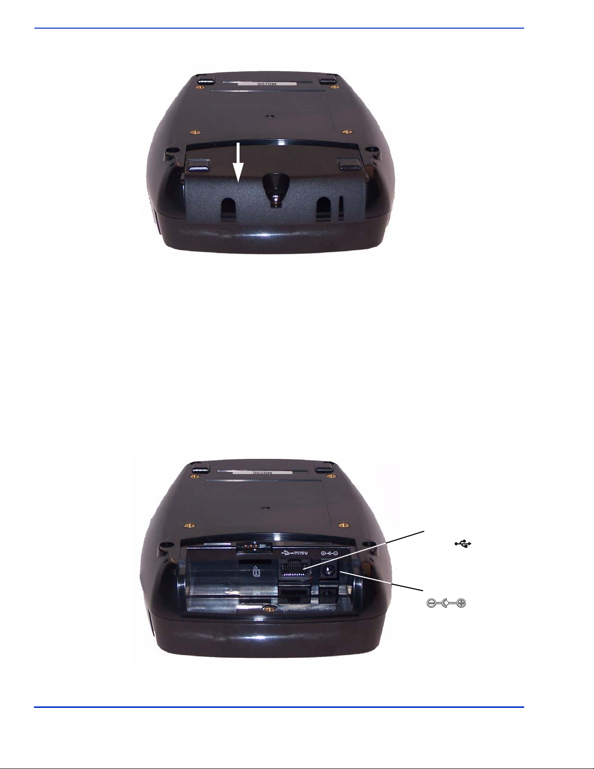
The ViVOpay 8100 connectors are beneath a cover on the bottom of the reader.
To access the connectors
1. Turn over the ViVOpay 8100 so that the connector cover is visible.
2. Use a Phillips #1 screwdriver to remove the captive screw that holds the connector cover
in place.
ViVOpay 8100 User Guide 9
Installing the ViVOpay 8100
3. Slide the connector cover away from the ViVOpay 8100.
If the captive screw catches, invert the ViVOpay 8100 to remove the connector cover.
Installing a SAM Card
The ViVOpay 8100 has a single SAM card slot for an optional SAM card. If you are using a SAM card
in your application, insert the SAM card as shown by the SAM card icon.
Warning:
Do not insert or remove a SAM card while the ViVOpay 8100 is powered. This will cause
permanent damage to the SAM card.
Connecting Power and Data
There are connectors for data and power inside the connector cover. There is also access to the
SAM card slot if you are using this option.
To connect the ViVOpay 8100
1. Position the ViVOpay 8100 so that you can access the data and power connectors.
Data Port
Power
RS232

ViVOpay 8100 User Guide 10
Installing the ViVOpay 8100
2. Insert the power cable into the power connector.
3. Insert the data cable into the 10-pin RJ45 connector directly beside the power socket.
ViVOpay 8100 User Guide 11
Installing the ViVOpay 8100
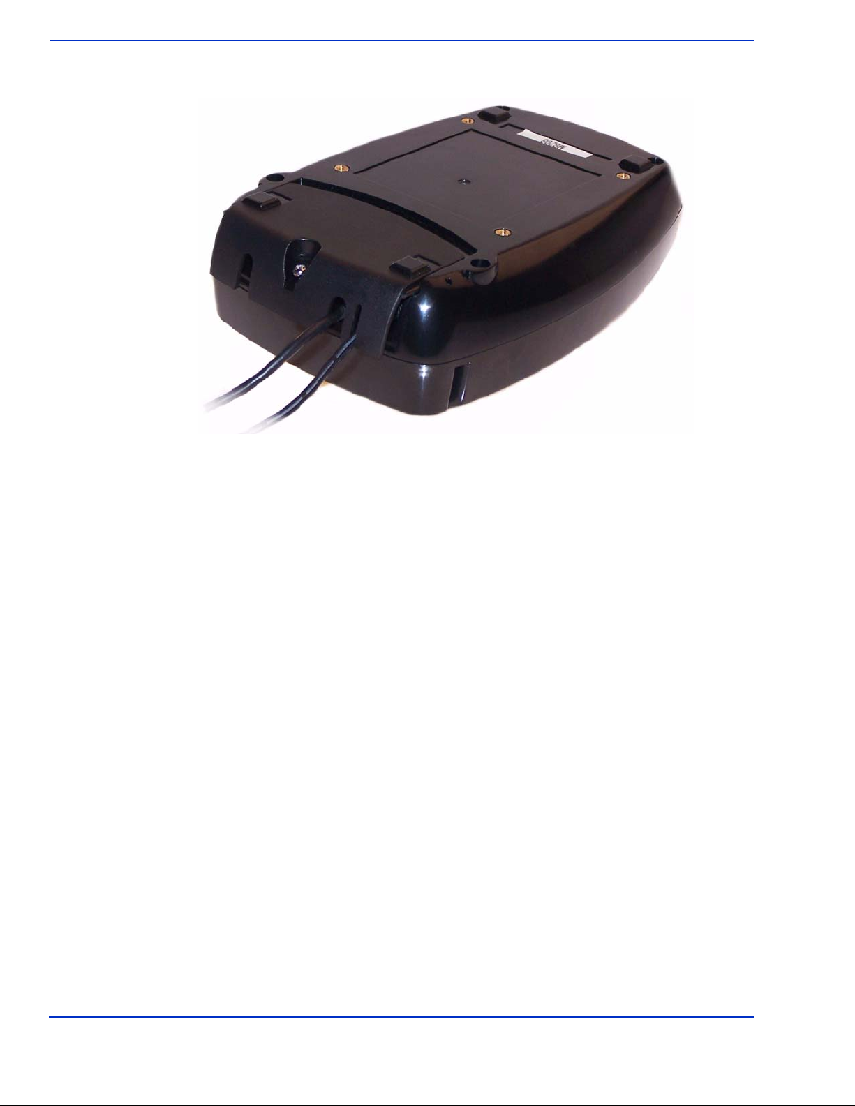
4. Pass the cables through the slots in the connector cover. Use the narrow slot for the power
cable to provide strain relief.
5. Replace the cover and secure it with the retaining screw.
6. Turn the ViVOpay 8100 keypad side up.
7. Attach the data cable from the ViVOpay 8100 to the appropriate port on the POS.
8. Plug in the power supply if required or make sure the POS is powered on. The ViVOpay
8100 beeps twice and the left LED illuminates. The ViVOpay 8100 may take up to 30
seconds to finish booting.
The ViVOpay 8100 displays the opening set of screens before it displays the
Welcome
screen. The
opening screens include:
• ViVOtech screen
• Copyright screen
• Firmware version screen
The reader should then display
Welcome
or
Please present card
or similar wording, depending
upon the POS application.
If the reader fails to power up, try reseating the power connector (or change to a different power
outlet).
If the reader still fails to power up, try replacing the power supply. If the reader still fails to power up,
and the power supply is definitely good, contact your local support representative. For more
troubleshooting information, see “Troubleshooting” on page 16.

ViVOpay 8100 User Guide 12
Installing the ViVOpay 8100
Mounting the ViVOpay 8100 to a Surface
The ViVOpay 8100 can be mounted to a surface to prevent it from being accidently dislodged or
repositioned.
To mount the ViVOpay 8100
1. Drill four 3.5mm (9/64 inch) holes in the surface where the ViVOpay 8600 will be mounted.
Use the hole spacing shown in Figure 4.
Figure 4. Mounting hole locations
2. Position the ViVOpay 8100 over the mounting holes and use four M3 screws (not supplied)
long enough to secure the ViVOpay 8100 to the mounting surface.
Mounting Holes x4
76.20 mm
3.0 inches
76.20 mm
3.0 inches
ViVOpay 8100 User Guide 13
Installing the ViVOpay 8100
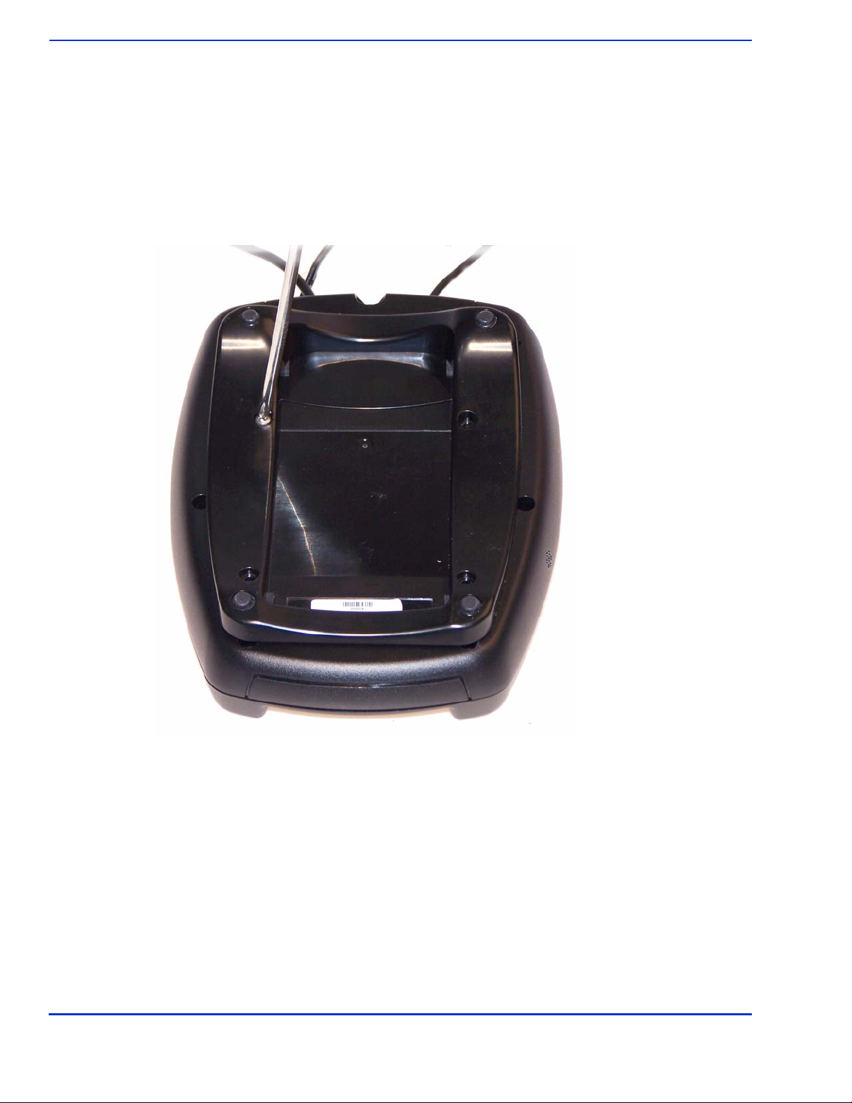
Mounting the Wedge Bracket
The optional wedge bracket tilts the ViVOpay another 11° for greater privacy. The wedge bracket is
fastened to the ViVOpay 8100 with the four mounting holes.
To mount the wedge bracket
1. Align the mounting bracket over the mounting holes with the thickest end over the
connector cover.
2. Fasten in place with four M3 screws as shown in Figure 5.
Figure 5. Attaching the wedge bracket

ViVOpay 8100 User Guide 14
Installing the ViVOpay 8100
Testing the Installation
After you have completed the installation and have checked for PCI 2.1 conformance, check that the
ViVOpay 8100 and the POS are communicating correctly by performing a sample transaction.
Testing a Contactless Read
Present the contactless card/fob/phone flat against the touch screen and so that maximum surface
area is parallel to the screen.
When a card/fob/phone has been successfully read, the ViVOpay 8100 beeps and illuminates all four
green LEDs. For an alternate test, see “RFID and Antenna Test” on page 21.
ViVOpay 8100 User Guide 15
Installing the ViVOpay 8100
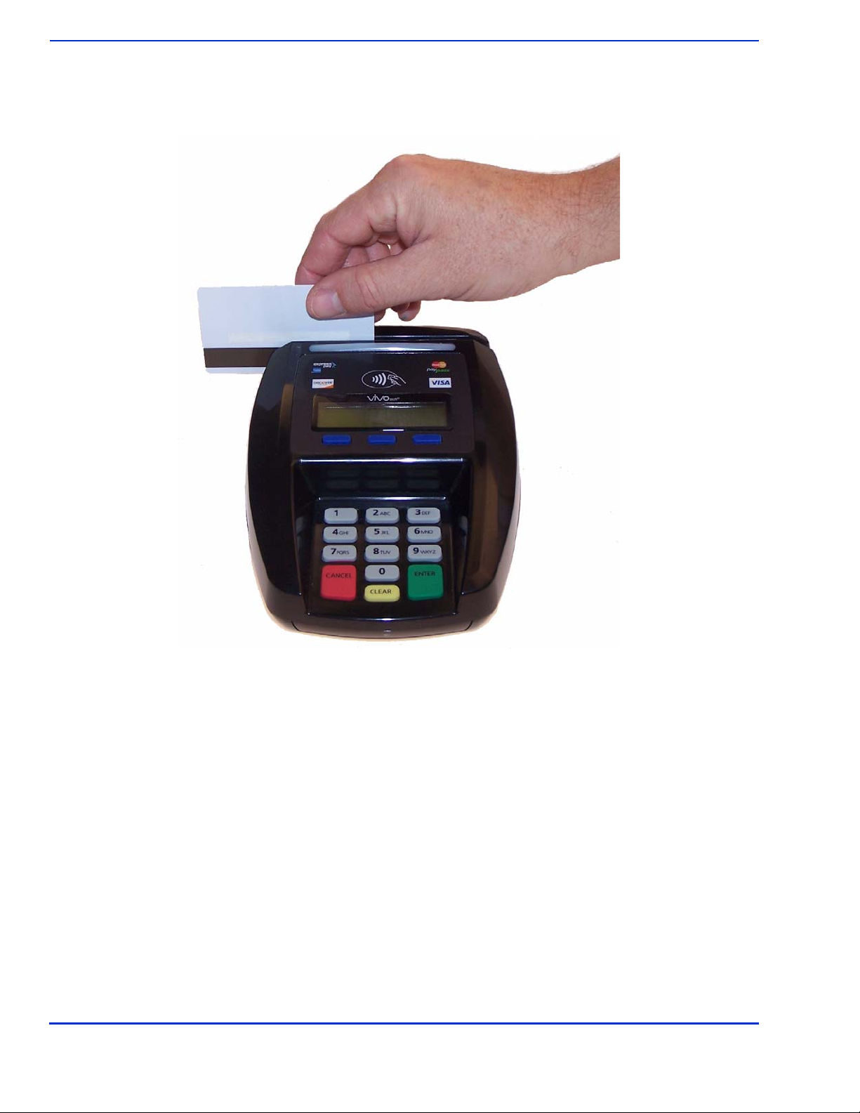
Testing a Magnetic Stripe Card Read
To test the magnetic stripe reader, pass a test magnetic stripe card through the reader slot. Orient
the card with the magnetic stripe at the bottom facing you as shown below.
When a magnetic stripe card has been read successfully, the ViVOpay 8100 beeps and illuminates
all four green LEDs. For an alternate test, see “Magstripe Test” on page 20.
Testing a Transaction
The exact wording that appears on the ViVOpay 8100 depends on the POS application.
To test a transaction
1. Ring up a transaction on the POS. The ViVOpay 8100 may show Welcome or similar
wording.
2. Present a card/fob/phone in close proximity to the reader or swipe a magnetic stripe card.
3. A single beep and LED flash indicates that the card has been validated. The ViVOpay 8100
may display Processing or similar wording while the transaction is being processed.
4. If the POS software requires a PIN entry, you will see Please enter PIN. Use the keypad
to enter the PIN.
5. A receipt is printed by the POS with the purchase amount. The ViVOpay 8100 may show
Thank You or similar wording for a successful transaction.

ViVOpay 8100 User Guide 16
Chapter 3
Troubleshooting and Maintenance
Troubleshooting
The ViVOpay 8100 readers are reliable and easy to troubleshoot. The components that may require
troubleshooting include the power supply, the reader, and the data cable.
Symptom Possible Cause Remedy
General Issues
Reader does not appear to be
powered on—no LEDs lit, no
LCD display.
• Reader not powered on.
• Incorrect power supply used.
• Check cable connections.
• Verify that power is on and correct voltage and
current are present.
• Replace the power supply.
• Verify that power cable plug is fully inserted.
• Replace the reader.
Reading Cards/Fobs/Phones
LEDs do not light and beeper is
not audible when
card/fob/phone is presented.
• Card/fob/phone not properly
presented.
• Metal or RF interference.
• Firmware issue (contact your local
support representative).
• Reader not powered on or incorrect
voltage.
• Incorrect power supply used.
• Unsupported card/fob/phone used.
• Present card/fob/phone closer to the reader
and ensure it’s parallel to the reader’s display.
• Verify that the card/fob/phone is valid/current.
• Test with “ViVOcard Contactless Test Card”
part number 241-0015-03.
• Try a different card/fob/phone.
• Verify that the unit is not near any large metal
objects.
• Verify that correct firmware is loaded (local
support representative only).
• Verify that power is on and correct voltage and
current are present.
• Verify that power cable plug is fully inserted.
• Replace the reader.
Some cards/fobs/phones read,
but not all.
• Wrong firmware (contact your local
support representative).
• Possible bad card/fob/phone.
• Unsupported card used.
• Verify that correct firmware is loaded on
reader (local support representative only).
• Check to see if card/fob/phone is damaged.
• Try a different card/fob/phone.
Communication to POS/ECR
No data is received, or data is
garbled.
• Faulty or incorrect cable connections.
• Unsupported card used.
• Contactless application is not
installed on terminal (for serial
connections only).
• Magstripe card not swiped correctly.
• Magstripe card not level during card
swipe.
• The POS application is not using the
correct communications parameters.
• Check that the cable connection is secure and
in the correct port on the POS/ECR.
• Check that the POS/ECR has the correct
software application to accept data from the
contactless reader (may need assistance from
the POS vendor).
• Try a different card/fob/phone or magstripe
card if testing the magstripe reader.
• If testing with the magstripe card, try turning
the card around; make sure that the card is
level during the card swipe.
• Contact the payment processor for an
application upgrade.
• Check that the cable is correctly attached to
the back of the ViVOpay 8100
• Check the POS application.
Table of contents
Other Vivotech Payment Terminal manuals


