2
Specications
I
Model Number AE-238, AE-243 AE-23A, AE-23B, AE-
23C, AE-23D
AE-239, AE-244 AE-23E, AE-23F
Power Input 24V AC/ DC 24V AC/ DC PoE: 50~57V DC PoE: 30/60/95W, 50~57V
DC
Max. Output power
budget
30W 80W, 100W (-AIW) 30W 25W - 30W PoE PSE
48W - 60W PoE PSE
72W - 95W PoE PSE
Power Consumption Window heater: 10W;
Blower: 2W; Camera: 6 ~
8W
Window heater: 10W;
Blower: 2W; Camera: 6
~ 8W; Cold start heater:
30W
Window heater: 10W;
Blower: 2W; Camera: 6 ~
8W; IR: 6W
Window heater: 10W;
Blower: 2W; Camera: 6 ~
8W; Wiper: 6W
Environmental
Operation Temp.
-20°C ~ +65°C (-4°F ~
+149°F)
-20°C ~ +65°C
-20°C ~ +50°C (w/ IR)
-24°C ~ +50°C (Cold start)
-20°C ~ +65°C
-20°C ~ +50°C (w/ IR)
-20°C ~ +65°C
-20°C ~ +50°C (w/ IR)
Window heater ON/OFF ≤ 30°C (86°F) ON; ≥ 35°C
(95°F) OFF
≤ 30°C (86°F) ON; ≥ 35°C
(95°F) OFF
≤ 30°C (86°F) ON; ≥ 35°C
(95°F) OFF
≤ 30°C (86°F) ON; ≥ 35°C
(95°F) OFF
Blower Control ≥40°C (104°F) ON; ≤ 35°C
(95°F) OFF
≥40°C (104°F) ON; ≤ 35°C
(95°F) OFF
≥40°C (104°F) ON; ≤ 35°C
(95°F) OFF
≥40°C (104°F) ON; ≤ 35°C
(95°F) OFF
Protection Level IP67, IK10 IP67, IK10 (IP66 w/ wiper) IP67, IK10 IP67, IK10 (IP66 w/ wiper)
Construction Die-cast Aluminum Alloy Die-cast Aluminum Alloy Die-cast Aluminum Alloy Die-cast Aluminum Alloy
Coating White epoxy powder
coating
White epoxy powder
coating
White epoxy powder
coating
White epoxy powder
coating
Dimensions 415 (L) x 170 (W) x 125 (H)
mm
502.8 (L) x 170 (W) x
135.5 (H) mm
415 (L) x 170 (W) x 125 (H)
mm - IR not included
502.8 (L) x 170 (W) x 135.5
(H) mm - IR not included
Net Weight 2,2kg (4.84 lb) 2,7kg (5.95 lb), 2,8kg (6.18
lb - wiper model)
2,2kg (4.85 lb) 2,7kg (5.95 lb), 2,8kg (6.18
lb - wiper model)
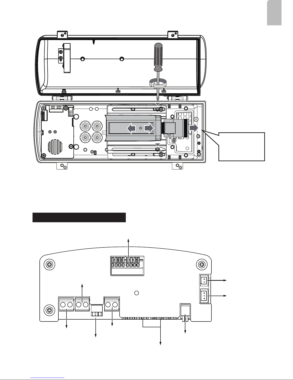
UNPACKING:
Unpack carefully. Electronic components can be damaged if improperly handled or
dropped. If an item appears damaged in shipment, place it properly in its carton and
notify the shipper.
IMPORTANT!:
1. Read and follow Instructions: All operating and user instructions should be read and
followed before the unit is to be operated.
2. Electrical Connections: Only a qualied electrician is allowed to make electrical
connections.
If you plan to install this camera enclosure into a tropical, sea coastal, or an environment
where salt water or corrosive industrial waste water/moist are present, please seal each
stainless steel screws and ttings with a silicon grease compounds. This will help prevent
electrolysis to occur and extend the life span of the camera and housing.
IMPORTANT:
1. Disconnect devices: A readily accessible disconnect device in the building installation wiring
should be incorporated.
2. Electrical Connection: Only a qualied electrician is allowed to make electrical connections.