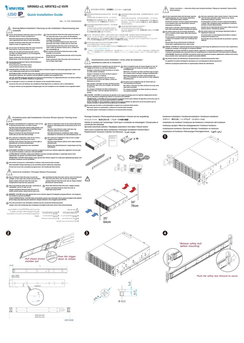
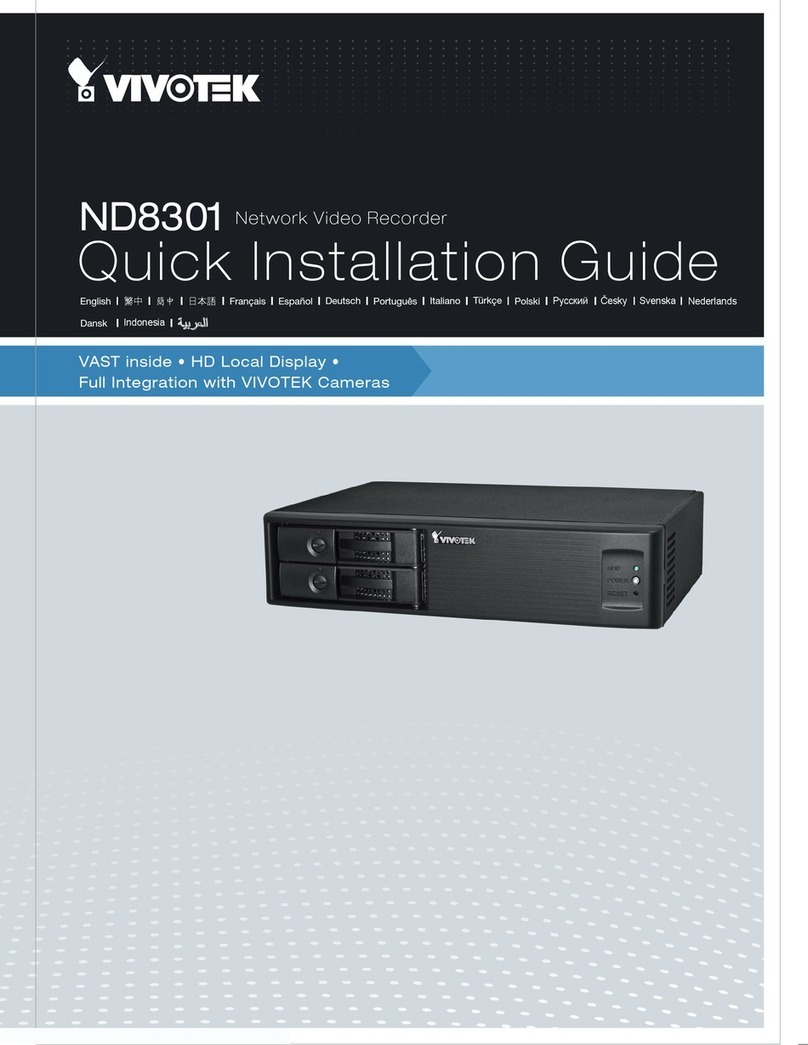
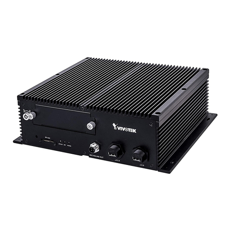
Vivotek NV9311P User manual

VIVOTEK–Built with Reliability
User's Manual–1
Rev. 1.6.1.11
Rev. 1.0
User’s Manual
H.265/H.264 Codec • 802.3af/at PoE • HDMI/VGA • G-sensor • GPS • 8/16 CH • -40ºC ~ 55ºC • EN50155
Solid Connection for Shock & Vibration • SATA or SSD • Programmable Delay ON/Off
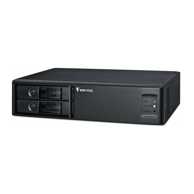
Mobile NVR
NV9311P, NV9411P
NV9311P-M12, NV9411P-M12
Rev. 1.1

VIVOTEK–Built with Reliability
2–User's Manual
Table of Contents
Chapter One Hardware Installation and Initial Conguration ...................................................................................... 7
Introducing the Network Video Recorder ............................................................................................................... 7
Special Features ............................................................................................................................................. 7
Safety .............................................................................................................................................................. 8
Installation Instructions .......................................................................................................................................... 9
Chapter 1 Hardware ................................................................................................................................................. 10
Dimension Drawing .............................................................................................................................................. 10
Interface Connectivity........................................................................................................................................... 11
Installation ............................................................................................................................................................ 20
LED Indicators...................................................................................................................................................... 36
Power Up and Power Down ................................................................................................................................. 37
Section One Management over a Local Console...................................................................................................... 40
Chapter Two Introduction to the Local Console Interface.......................................................................................... 40
2-1. How to Begin.......................................................................................................................................... 42
2-2. Tracking and Viewing the Mobile NVR Videos on VAST2............................................................................. 48
2-2-1. Adding NVR as a VAST2 Sub-station ................................................................................................. 48
2-2-2. Conguring GPS and E-Map .............................................................................................................. 50
Alarm .................................................................................................................................................................... 57
2-2-3. Playback Videos on the NVR H.D.D. from the VAST2 CMS Software .............................................. 62
2-3. Operation on Camera View Cell.................................................................................................................... 66
2-3-1. PTZ Panel........................................................................................................................................... 66
2-3-2. Digital zoom Panel.............................................................................................................................. 69
2-3-3. Play Recording Clips Panel ................................................................................................................ 70
2-3-4. DI/DO.................................................................................................................................................. 71
2-3-5. Others ................................................................................................................................................. 71
2-3-6. Right-click Commands........................................................................................................................ 72
Chapter Three Conguation Using the Local Console .............................................................................................. 73
The Main Control Portal ....................................................................................................................................... 73
3-1. Layout .................................................................................................................................................... 73
3-2. DI/DO ..................................................................................................................................................... 73
3-3. Search recording clips ........................................................................................................................... 74
3-3-1. Time Search................................................................................................................................. 74
3-3-2. Alarm Search ............................................................................................................................... 78
3-3-3. Storyboard ................................................................................................................................... 81
3-4. Export recordings................................................................................................................................... 85
3-5. Settings .................................................................................................................................................. 87
3-5-1. Settings–Overview....................................................................................................................... 87
3-5-2. Settings–Camera–Management.................................................................................................. 88
3-5-3. Settings–Camera–Recording....................................................................................................... 93
3-5-4. Settings–Camera–Recording....................................................................................................... 94

VIVOTEK–Built with Reliability
User's Manual–3
3-5-5. Settings–Camera–Media ............................................................................................................ 96
3-5-6. Settings–Camera–Image.......................................................................................................... 102
3-5-7. Settings–Camera–Motion Detection......................................................................................... 104
3-5-8. Settings–Camera–PTZ settings................................................................................................ 105
3-5-9. Settings–Alarm–Alarm.............................................................................................................. 107
3-5-10. Settings–Alarm–Email ............................................................................................................ 120
3-5-11. Settings–System–Information ................................................................................................. 121
3-5-12. Settings–System–Maintenance .............................................................................................. 122
3-5-13. Settings–System–Display....................................................................................................... 123
3-5-14. Settings–System–PoE management...................................................................................... 124
3-5-15. Settings–System–Power management................................................................................... 125
3-5-16. Settings–System–UPS ........................................................................................................... 126
3-5-17. Settings–System–Log............................................................................................................. 127
3-5-18. Settings–User ......................................................................................................................... 129
3-5-19. Settings–Storage .................................................................................................................... 131
3-5-20. Settings–Network.................................................................................................................... 134
Settings–Network–IP........................................................................................................................... 134
Settings–DDNS................................................................................................................................... 139
Settings–Service ................................................................................................................................. 140
3-6. Devices ............................................................................................................................................... 144
GPS & G-sensor ................................................................................................................................. 144
3-7. Information .......................................................................................................................................... 145
Section Two Management over a Web Console .................................................................................................... 146
Chapter Four Login and Getting Started ................................................................................................................ 147
4-1. Login .......................................................................................................................................................... 147
4-2. Graphical Layout and Screen Elements–Liveview..................................................................................... 151
4-2-1. Camera List Panel ........................................................................................................................... 152
4-2-2. Layout .............................................................................................................................................. 154
4-2-3. Layout contents ............................................................................................................................... 155
4-2-4. Logo & Menu ................................................................................................................................... 155
4-2-5. View Cell panel ................................................................................................................................ 156
Adding Cameras to View Cells................................................................................................................... 156
4-2-6. PTZ panel ........................................................................................................................................ 165
4-2-7. Alarm panel...................................................................................................................................... 167
4-3. Graphical Layout and Screen Elements–Search recording clips ............................................................... 171
4-3-1. Camera List Panel ........................................................................................................................... 172
4-3-2. Search Recording Clips Layout ....................................................................................................... 173
4-3-3. Logo & Menu ................................................................................................................................... 173
4-3-4. View Cells in Search Recording Clips.............................................................................................. 174
Search Recording Clips Control Panel ...................................................................................................... 175
4-3-5. Alarm Panel ..................................................................................................................................... 177
4-3-6. Calendar Panel ................................................................................................................................ 178
Chapter Five System Settings................................................................................................................................ 179
Chapter Six Operation............................................................................................................................................ 181
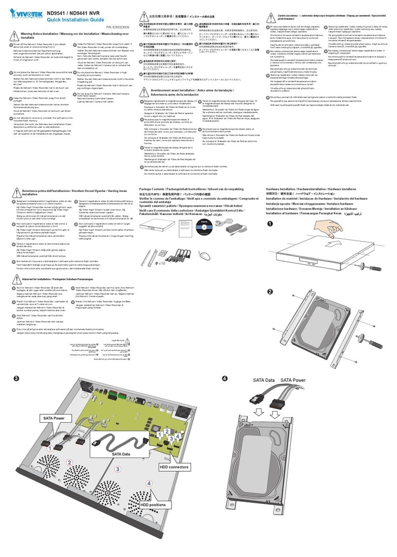
VIVOTEK–Built with Reliability
4–User's Manual
6-1. Liveview ...................................................................................................................................................... 181
6-1-1. Placing Cameras into the Layout...................................................................................................... 181
6-1-2. PTZ and Other Screen Controls ....................................................................................................... 185
6-1-3. Audio................................................................................................................................................. 188
6-1-4. Camera Properties and Controls ...................................................................................................... 189
6-1-5. Alarm Panel ...................................................................................................................................... 190
6-1-6. Layout view Control Buttons ............................................................................................................. 191
6-2. Search Recording Clips .............................................................................................................................. 192
6-2-1. Begin Playback and Search for Past Recordings ............................................................................. 192
6-2-2. Past Alarms and Bookmarks............................................................................................................. 193
6-2-3. Synchronous Playback ..................................................................................................................... 194
6-2-4. Export media..................................................................................................................................... 195
6-2-5. Time Search...................................................................................................................................... 196
Safety and Compatibility.......................................................................................................................................... 198
1. No storage system is completely fail-safe. Damage to data might occur due to le system
corruption, operating system malfunction, virus infection, HDD component failures, and so on.
Therefore, it is highly recommended to regularly back up your data, and VIVOTEK disclaims
responsibilities of data loss or recovery.
2. Always power o the system using the power down button on system desktop. Do not
disconnect the power cord while the system is still operating. Doing so will result in data
inconsistencies. The normal power-o procedure allows cached data to be written to disks.
WARNING:

VIVOTEK–Built with Reliability
User's Manual–5
Revision History
* Rev. 1.0: Initial release.
Note that the Settings pages on the web console has been changed to that identical to the
local console.
The limitations on text entry length is listed below:
• User account: 64 alpha-numeric characters
• Account password: 64 alpha-numeric characters
• Path name: 256 alpha-numeric characters
• IP domain name: host.xxx.yyy.zzz–63 bytes; total: 253 bytes
• Email account: local@domain_name_part–local -63bytes; domain_name_part–253 bytes.
• Do not use < >)( " % ; # & +-\
Symbols and Statements in this Document
i
INFORMATION: provides important messages or advices that might help prevent inconvenient
or problem situations.
NOTE: Notices provide guidance or advices that are related to the functional integrity of the
machine.
Tips: Tips are useful information that helps enhance or facilitate an installation, function, or
process.
WARNING! or IMPORTANT: These statements indicate situations that can be dangerous or
hazardous to the machine or you.
Electrical Hazard: This statement appears when high voltage electrical hazards might occur
to an operator.
* Rev. 1.1: Added the description for the M12 models, NV9311P-M12 and NV9411P-M12.
Also added new system LED denitions for system troubleshooting when unable to
power up. See page 36.

VIVOTEK–Built with Reliability
6–User's Manual
Read Before Use
The use of surveillance devices may be prohibited by law in your country. The Network Camera
is not only a high-performance web-ready camera but can also be part of a exible surveillance
system. It is the user’s responsibility to ensure that the operation of such devices is legal before
installing this unit for its intended use.
It is important to first verify that all contents received are complete according to the Package
Contents listed below. Take note of the warnings in the Quick Installation Guide before the
Network Camera is installed; then carefully read and follow the instructions in the Installation
chapter to avoid damage due to faulty assembly and installation. This also ensures the product is
used properly as intended.
The Network Camera is a network device and its use should be straightforward for those who
have basic networking knowledge. It is designed for various applications including video sharing,
general security/surveillance, etc. The Configuration chapter suggests ways to best utilize the
Network Camera and ensure proper operations. For creative and professional developers, the
URL Commands of the Network Camera section serves as a helpful reference to customizing
existing homepages or integrating with the current web server.
The operating system and management software are installed on a ash memory mounted on
the main board. Except for running the plug-ins for the onscreen control on a web console, there
is no need to install software.
NOTE:
Package Contents
1. Mobile-NVR
2. DC Power cable
3. QIG
4. HDD screws
5. GPS receiver
6. MIC in/Line out cable
7. HDD lock keys (two packs)
8. Network Cable retention bracket set (RJ45 version) and screws.
Optional Accessories:
1. Wi-Fi module & antenna
2. 4G module & antenna

VIVOTEK–Built with Reliability
User's Manual–7
Chapter One Hardware Installation and Initial
Conguration
Introducing the Network Video Recorder
The NV9311P/ NV9411P is a mobile NVR designed for the transportation surveillance that pro-
vides powerful 1080p 8-CH or 16-CH real-time live display and recording using the advanced
H.265 video compression technology. The 8 802.3at PoE ports provide the ease of connections
with cameras. The NVR comes in a rugged design that is compliance with EN 50155/ MIL-STD-
810G standard.
Embedded with G-sensor and GNSS module to provide information such as G-sensor event
and speed event, and have multiple Network interfaces as LAN, WiFi and LTE for different Net-
work connection requirements. Implemented with VIVOTEK’s VAST2 software, the GPS track-
ing locations are instantly displayed on GoogleMap. Live videos can also be displayed remotely
allowing instant access for a complete safety control.
For the installation on vehicles, the NVR supports ignition startup, delay start and shutdown,
scheduled start/shutdown. The NVR also features as wide range of power input, aluminum die-
case chassis, built-in heater, surge protection, and the protection for shock and vibration.
Special Features
● Runs on embedded Linux
● 1 x HDMI and 1 x VGA for local display
● 1 x HDD bay, for a max. capacity of 2TB
● 1 x Gigabit RJ45 Ethernet port;
● 3 x USB Ports (USB 2.0)
● Size: 284 mm (W) x 267.4 mm (D) x 90 mm (H). Weight: 4.12kg.
● 8- or 16-CH Live View & 4-CH Synchronous Playback (web console)
● H.265 / H.264 / MJPEG
● PTZ Support
● Snapshot / Export Media
● Digital zoom Video Control
● Terminal block pins for DI/DOs.
● Configuration Backup / Restore
● Compatible with VIVOTEK VAST Central Management Software*
● Integration with VIVOTEK Network Cameras
● VIVOTEK iViewer Support (iOS/Android cellphone/hand-held devices)
*The VIVOTEK VAST Central Management Software is not included in the package.

VIVOTEK–Built with Reliability
8–User's Manual
Safety
This product is connected to a fuse box in the passenger compartment before it is connected
to the vehicle battery, and the fuse in a fuse box is UL listed as an automotive fuse.
Use the appropriate flexible and SAE wiring to connect to a fuse box.
This product is installed in the passenger compartment.
This product must be installed and maintained by qualified service personnel.
Never open the housing of the power supply unit.
Install and operate the system only in a dry, weather-proof location.
Observe the following safety factors:
• Is there visible damage to the system or power cord
• Is the system operating correctly.
• Has the system been exposed to rain or moisture
• Has the system been in a long storage under harsh conditions or exposed to
unconforming stress.
The relevant electrical engineering regulations must be complied with at all times during
installation.
Ensure that all maintenance and repair work is handled by qualified personnel such as
electrical engineers or network specialists.
Read this manual before installing or operating the system. The documentation contains
important safety instructions about permitted uses.
The rated DC input is: 10~48V, maximum 15A@ input 10V; the PoE output: 802.3af or
802.3at, up to 30W per channel, total budget is 64W.
If a fault occurs, disconnect the power cord from the power supply.
Do not install the system close to heaters or other heat sources. Avoid locations with direct
sunlight.
Use only the cables shipped with system or use appropriate cables that can withstand electro-
magnetic interference.
セキュリティ基準(新規則第 34 条の 10)
「本製品は 電気通信事業者(移動通信会社、固定通信会社、インターネットプロバイダ等)
の通信回線(公衆無線 LAN を含む )
に直接接続することができません。本製品をインターネットに接続する場合は、必ずルータ等
を経由し接続してください。」

VIVOTEK–Built with Reliability
User's Manual–9
Installation Instructions
Warning:
Read the installation instructions before connecting the system to the power source.
Warning:
This equipment is intended to be used in a Restricted Access area, such as a cabinet
or a dedicated computer room. Access should only be allowed to SERVICE PERSONS
or USERS who have been instructed on proper handling of the device’s metal chassis,
which may become hot during operation. Further, access should be restircted through the
use of a key or secure identity system, to ensure only qualified personnel have access to
the restricted access area.
Warning:
Calculate the maximum possible electric current on each power wire and common wire.
Observe all electrical codes indicating the maximum current for each wire size. If a cur-
rent goes above the maximum ratings, the wiring can become overheated, causing dam-
ages to your equipment.
Warning:
The system must be disconnected from all sources of power and the power cord re-
moved from the power supply module(s) before accessing the chassis interior to install or
remove system components.
Warning:
Only trained and qualified personnel should be allowed to install, replace, or service this
equipment.
Warning:
Installation of the equipment must comply with local and national electrical codes.
Warning:
Ultimate disposal of this product should be handled according to all national laws and
regulations.
Warning:
Do not run signal or communications wiring and power wiring in the same routing conduit.
Wires with different signal characteristics should be separately routed.
Warning:
The product is intended to be mounted on a properly grounded mounting surface, such
as a metal equipment panel.
Warning:
The product is designed to perform without a cooling fan. It is recommended that the
product is installed with at least a 5mm clearance on all sides for heat dissipation.

VIVOTEK–Built with Reliability
10–User's Manual
Dimension Drawing
268
170
214
3.5
90
284
276.7
230
27
M3-tapping-4x
5.5-4x
Chapter 1 Hardware
1

VIVOTEK–Built with Reliability
User's Manual–11
Interface Connectivity
USB
Audio
LEDs
SD card
2.5”HDD or SSD
Tray lock
Reserved
Front Panel
2
You should pull the retention cap up after you install an SD card
to prevent disconnection by vibration or impact.
Note that the front panels of the NV9311P/NV9411P and the M12 version (NV9311P-M12/
NV9411P-M12) are identical.

VIVOTEK–Built with Reliability
12–User's Manual
Rear Panel - NV9311P & NV9411P
4G
HDMIVGA
Terminal block
USB
GbE
Camera 01 Camera 02 Camera 03
Camera 04 Camera 06
Camera 05
Camera 07 Camera 08 Camera 09
Wi-Fi
antenna
GPS
antenna
12V ~ 48V
LTE
Antenna
RS232
PoE ports 802.3af/at
IP cameras
Chassis
ground
Main LTE
Black
Yellow
Red
ACC
DC IN+
Chassis ground
802.3af/at, total power budget is 64W.
4G
HDMIVGA
Terminal block
USB
GbE
Camera 01 Camera 02 Camera03
Camera 04 Camera 06
Camera 05
Camera 07 Camera 08 Camera09
Wi-Fi
antenna
GPS
antenna
12V ~ 48V
LTE
Antenna
RS232
PoE ports 802.3af/at
IP cameras
Chassis
ground
Main LTE
Black
Yellow
Red
ACC
DC IN+
Chassis ground
LAN / WAN
8-pin A code
4-pin D code
Rear Panel - NV9311P-M12 & NV9411P-M12

VIVOTEK–Built with Reliability
User's Manual–13
SIM card: Access from the Bottom
The GPS (Global Positioning System) connectivity can apply for speed and route tracking data
on video streams. For specialized wireless transmission, a SIM card is necessary for the LTE
module. The SIM card can be installed by opening a small cover from the bottom of the NVR.
Reset button
SIM socket
Reset button
The SIM socket.

VIVOTEK–Built with Reliability
14–User's Manual
4”, 10cm
3”, 7.6cm Rear
Front
Cabling Clearance
It is recommended to have a clearance for making the cabling connections at the front and the
the rear of the chassis. Front: 4", Rear: 3".
Connector Pinouts–Front Panel
1
Brown
2
White
4
Black
3
Blue
4C
3C
Wire Color NOTE
Brown GND
White GND
Blue Line out
Black MIC in
Audio IN/OUT–M12

VIVOTEK–Built with Reliability
User's Manual–15
Connector Pinouts–Rear Panel
123
4G
567
8G
1
ALARM OUT
234
10887654321
DI GND DI8 DI7 DI6 DI5 DI GND DI4 DI3 DI2 DI1
20 19 18 17 16 15 14 13 12 11
N/A N/A DO4_
COM
DO4_
NO
DO3_
COM
DO3_
NO
DO2_
COM
DO2_
NO
DO1_
COM
DO1_
NO
Terminal Block
Terminal Block Connections
The terminal block pinouts is shown as follows:
Connect your relay or external devices’ signal wires to the system, the system will automatically
detect the current signal status. You can then trigger the external devices using the DI/DO
panel on the live view.
You can also congure the system alarm setting for the system to automatically trigger a DO on
the occurrence of system events. See Alarm settings on page 107.
Normally Open
pin
Common pin
Normally Closed
pin
Coil
The pins are listed and described from left to right as shown in the drawing above.
Pin Description NOTE
DI no. 1 ~ 8 Open/short to GND
G Pins #1~4 share a common ground.
Pins #5~8 share a common ground.
NO Normally open. Use the DO trigger
buttons on the live view window to
trigger the digital output.
COM Common pin

VIVOTEK–Built with Reliability
16–User's Manual
15
69
123456789
N/A RXD TXD DTR GND DSR RTS CTS N/A
RS232
15
11
6
10
15
54321
GND GND BGR
10 9 8 7 6
GND VGA_5V GND GND GND
15 14 13 12 11
SCL Vsync Hsync SDA GND
VGA
1
2
3
4
5
6
123456
DC IN+ DC IN+ ACC DC IN- DC IN- DC IN-
Power Input
The Red DC IN+ connects to the vehicle battery positive.
The Black DC IN- connects to the vehicle battery negative or chassis ground.
The Yellow ACC connects to the ACC pin of the vehicle ignition key switch.

VIVOTEK–Built with Reliability
User's Manual–17
While routing the cables, the possible damage caused by impact, friction, and vibration should
be taken into consideration.
IMPORTANT:
Cable Pinouts
Black
Yellow
Red
M12 8-pin A code Ethernet
TxData+
RxData+
RxData-
TxData-
M12 4-pin D code Ethernet

VIVOTEK–Built with Reliability
18–User's Manual
You can connect the wiring through the vehicle electrical panel. When connecting to the
chassis ground, it is important that you are connecting to a grounding point that is not rusted.
If connecting to a non-steel ground screw, resistance can be high causing problems with
voltages supply.
Do not make ground connections to screws with thread locker compounds. They are insulated
from the chassis. Screws with thread sealers or those mounted on gaskets are not the good
choice for grounding.
IMPORTANT:
Connect the yellow wire to a vehicle's ignition switch's ACC pin. Red wire to the vehicle
battery output, and the Black wire to the chassis ground.
Black
Yellow
Red
ACC
DC IN+
Chassis ground

VIVOTEK–Built with Reliability
User's Manual–19
RF Antenna Connector
The NVR has 3 antenna connectors, one of which is the GSM/UMTS/LTE main antenna
connector, the others are UMTS/LTE auxiliary antenna connector and GPS/GLONASS
antenna connector. The Rrcommended antenna characteristics are described by the 2
following tables.
Recommended Passive Antenna Characteristics
Passive Recommended standard
Direction omnidirectional
Gain >-3dBi (avg.)
Input impedance 50 ohm
Eciency >50%
VSWR <2
Recommended Active Antenna Characteristics
Band Performance
TRP TIS
GSM850 ≥ 29dBm ≤ -104dBm
EGSM900 ≥ 29dBm ≤ -104dBm
DCS1800 ≥26dBm ≤ -104dBm
PCS1900 ≥26dBm ≤ -104dBm
WCDMA B1 ≥ 19dBm ≤ -104dBm
WCDMA B2 ≥ 19dBm ≤ -104dBm
WCDMA B5 ≥ 19dBm ≤ -104dBm
WCDMA B8 ≥ 19dBm ≤ -104dBm
LTE B1 ≥18dBm ≤ -92dBm
LTE B2 ≥18dBm ≤ -90dBm
LTE B3 ≥18dBm ≤ -89dBm
LTE B4 ≥18dBm ≤ -92dBm
LTE B5 ≥18dBm ≤ -90dBm
LTE B7 ≥18dBm ≤ -90dBm
LTE B8 ≥18dBm ≤ -89dBm
LTE B13 ≥18dBm ≤ -89dBm
LTE B17 ≥18dBm ≤ -89dBm
LTE B18 ≥18dBm ≤ -92dBm
LTE B19 ≥18dBm ≤ -92dBm
LTE B20 ≥18dBm ≤ -89dBm
LTE B38 ≥18dBm ≤ -92dBm
LTE B39 ≥18dBm ≤ -92dBm
LTE B40 ≥18dBm ≤ -92dBm
LTE B41 ≥18dBm ≤ -91dBm
3

VIVOTEK–Built with Reliability
20–User's Manual
Installation
4
Install a SIM card
Open the small maintenance panel at the bottom of the NVR. You should subscribe to a service
with a wireless service provider and obtain a SIM card.
Reset button
SIM socket
Reset button
Install a SIM card to the SIM socket. The reset button is also located in here.
Refer to page 134 for the Network IP and
the default gateway conguration.
Other manuals for NV9311P
1
This manual suits for next models
3
Table of contents
Other Vivotek DVR manuals

Vivotek
Vivotek ND8321 User manual

Vivotek
Vivotek ND8322P User manual

Vivotek
Vivotek ND8301 User manual

Vivotek
Vivotek ND8301 User manual

Vivotek
Vivotek NR7401 User manual

Vivotek
Vivotek NV9311P User manual

Vivotek
Vivotek ND9541 User manual

Vivotek
Vivotek ND8301 User manual

Vivotek
Vivotek ND8301 User manual

Vivotek
Vivotek NR8201 User manual