Vivotek NR7401 User manual


VIVOTEK - A Leading Provider of Multimedia Communication Solutions
2 - User's Manual
Table of Contents
Overview.......................................................................................................................................................3
Read before use��������������������������������������������������������������������������������������������������������������������������������������3
Package contents������������������������������������������������������������������������������������������������������������������������������������3
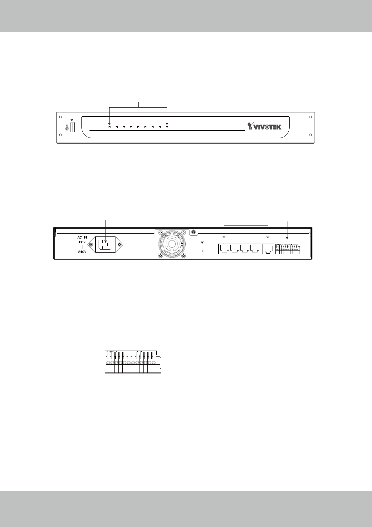
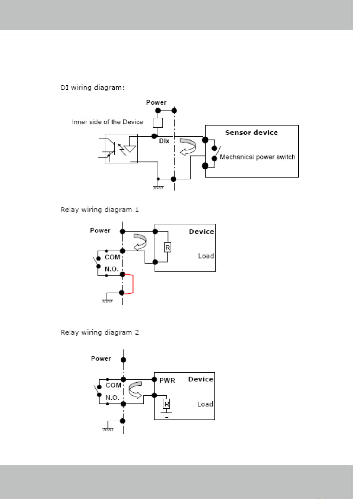
Physical description���������������������������������������������������������������������������������������������������������������������������������4
Installation ....................................................................................................................................................7
Hardware installation�������������������������������������������������������������������������������������������������������������������������������7
Network deployment��������������������������������������������������������������������������������������������������������������������������������8
Home Page.................................................................................................................................................16
Conguration ..............................................................................................................................................18
Device ���������������������������������������������������������������������������������������������������������������������������������������������������18
Network �������������������������������������������������������������������������������������������������������������������������������������������������20
LAN �������������������������������������������������������������������������������������������������������������������������������������������������������20
Access list ���������������������������������������������������������������������������������������������������������������������������������������������21
DDNS ����������������������������������������������������������������������������������������������������������������������������������������������������22
Security �������������������������������������������������������������������������������������������������������������������������������������������������24
Schedule �����������������������������������������������������������������������������������������������������������������������������������������������26
Recording Policy �����������������������������������������������������������������������������������������������������������������������������������28
Trigger ���������������������������������������������������������������������������������������������������������������������������������������������������31
System ��������������������������������������������������������������������������������������������������������������������������������������������������34
Maintenance������������������������������������������������������������������������������������������������������������������������������������������36
Backup ��������������������������������������������������������������������������������������������������������������������������������������������������37
System log���������������������������������������������������������������������������������������������������������������������������������������������38
Monitor........................................................................................................................................................39
User Interface of Monitor Page �������������������������������������������������������������������������������������������������������������39
Functions of Monitor Page ��������������������������������������������������������������������������������������������������������������������41
History ........................................................................................................................................................44
User Interface of History Page ��������������������������������������������������������������������������������������������������������������44
Functions of History Page ���������������������������������������������������������������������������������������������������������������������45
Appendix.....................................................................................................................................................50
Technical Specications ������������������������������������������������������������������������������������������������������������������������50

VIVOTEK - A Leading Provider of Multimedia Communication Solutions
User's Manual - 3
Overview
VIVOTEK NR7401 network video recorder provides an easy recording solution for VIVOTEK
network cameras and allows users to perform real-time monitoring and recording at the same time�
Supporting recording for up to 9 channels in both MPEG-4 and MJPEG formats, NR7401 provides
several recording options, including alarm recording, scheduled recording, and manual recording�
Installation is made easy because NR7401 can automatically detect and install VIVOTEK cameras
without any configuration� Furthermore, NR7401 has four 802�3af compliant PoE (Power over
Ethernet) ports that reduce cabling problems� NR7401 offers a user-friendly interface where users
can congure network settings as well as control camera movement. By installing a large-volume
SATA hard disk (up to 1TB) in NR7401, users can record high-denition video streams from mega-
pixel cameras for a long period without worrying about running out of storage capacity� NR7401
comes with a built-in gateway that separates network cameras from regular data network so the
inuence of video recording on bandwidth is minimized. NR7401 also has four digital input and one
digital out interfaces to allow for connection with external sensors and alarms� In addition, NR7401
offers an USB port, which can be used to connect with external storage devices for video backup�
Read before use
The use of surveillance devices may be prohibited by law in your country� It is the user’s
responsibility to ensure that the operation of such devices is legal before installing this unit for
its intended use�
It is important to rst verify that all contents received are complete according to the Package
contents listed below� Take notice of the warnings in Quick Installation Guide before the Network
Video Recorder is installed; then carefully read and follow the instructions in the Installation
chapter to avoid damages due to faulty assembly and installation� This also ensures the product
is used properly as intended�
The Network Video Recorder is a network device and its use should be straightforward for those
who have basic network knowledge� It is designed for various applications including audio/video
recording, general security/surveillance, etc. The Conguration chapter suggests ways to best
utilize the Network Video Recorder and ensure proper operations.
Package contents
■ NR7401
■ Power cord
■ Software CD
■ 3M Bumpon / Screws
■ Warranty card
■ Quick installation guide

VIVOTEK - A Leading Provider of Multimedia Communication Solutions
4 - User's Manual
Physical description
Front panel
Connectors
General I/O Terminal Block
This Network Camera provides a general I/O terminal block which is used to connect external
input / output devices. The pin denitions are described below.
1 2 3 4 5 6 7 8 9101112
1: Power
2: Relay output COM
3: Relay output N�O�
4: Digital Input 1
5: Digital Input 1 Ground
6: Digital Input 2
7: Digital Input 2 Ground
8: Digital Input 3
9: Digital Input 3 Ground
10: Digital Input 4
11: Digital Input 4 Ground
12: Ground
Power POE Status HDD WAN LAN1 LAN2 LAN3 LAN4
USB socket Status indicator
NR7401 Network Video Recorder
RESET
LAN4 LAN3 LAN2 LAN1 WAN
1 2 3 4 5 6 7 8 9101 112
Power cord socket Indented reset button General I/O
terminal block
Ethernet 10/100
RJ45 socket

VIVOTEK - A Leading Provider of Multimedia Communication Solutions
User's Manual - 5
DI/DO Diagram
Refer to the following illustration for connection method�

VIVOTEK - A Leading Provider of Multimedia Communication Solutions
6 - User's Manual
Status LED
The LED indicates the status of the Network Video Recorder�
LED Status Indication
Power Green Power on
Off Power off
POE Green Normal
Off Power off / POE fail
Status Green Normal
Blinking red Upgrading firmware
HDD (Hard disk) Blinking green Hard disk is accessed
Red Hard disk full or error
WAN On With connection
Off No connection
Blink Activity on WAN port
LAN1 On With connection
Off No connection
Blink Activity on LAN port 1
LAN2 On With connection
Off No connection
Blink Activity on LAN port 2
LAN3 On With connection
Off No connection
Blink Activity on LAN port 3
LAN4 On With connection
Off No connection
Blink Activity on LAN port 4
Hardware System Requirement
Computer:
■ Microsoft Windows XP Professional SP2 or above
■ Internet Explorer 6�0 or later
Hard disk:
SATA hard drive for up to 1TB
Hardware Reset
There is a indented reset button on the back panel of the Network Video Recorder� It is used to
reboot the Network Video Recorder or restore the Network Video Recorder to factory default�
Sometimes rebooting the Network Video Recorder could set it back to normal state� If the
problems remain after rebooted, restore the Network Video Recorder to factory default and
install again�

VIVOTEK - A Leading Provider of Multimedia Communication Solutions
User's Manual - 7
Reboot: Press and release the indented reset button� All status LED will extinguish and then
power on again. Wait for the Status LED to blink and then become steady green in normal state.
It takes about 30 seconds to complete the procedure�
Restore: Press the reset button continuously for over 3 seconds� All status LED will extinguish
and then power on again. Wait for the Status LED to blink and then become steady green in
normal state� Note that all settings will be restored to factory default� It takes about 50 seconds
to complete the procedure�
Installation
Hard Disk installation
Before using the Network Video Recorder, the rst step is to install a SATA hard disk for re-
corded video� Please follow the steps below:
1� Make sure the power is off�
2. Use a screwdriver to loose ve screws, and then slide to remove the upper cover.
3� Loose the screw and take out the hard disk bracket�
4� Put your hard disk into the bracket, and secure it with the supplied four screws�
5� Place your hard disk into the Network Video Recorder�
6� Slide the hard disk as the picture shows, and then secure it with the original screw�
7. Attach the upper cover, and then secure it with the original ve screws.
2
5
3
4
6
7
NOTE
► Please remember to format the hard disk
before strating recording� Please refer to
maintenance on page 37�
Power POE Status HDD WAN LAN1 LAN2 LAN3 LAN4 NR7401 Network Video Recorder
Steady green in normal state

VIVOTEK - A Leading Provider of Multimedia Communication Solutions
8 - User's Manual
Network deployment
Device Connection
1� Connect the supplied power cable from the NR7401 to a power outlet�
2� Connect NR7401 to Network Cameras and computer in LAN via LAN sockets� Because
NR7401 supports PoE, if the Network Camera is PoE-compliant (802�3af), it allows transmission
of power and data via single Ethernet cable�
3� If your want to access NR7401 over the Internet, connect NR7401 to the Internet via WAN
socket�
4� If you have external devices such as sensors and alarms, make connections from general I/O
terminal block�
RESET
LAN4 LAN3 LAN2 LAN1 WAN
1 2 3 4 5 6 7 8 9101112
Activity
Power/MIC
Internet
WAN
LAN
LAN
LAN
1
2
Network Camera
(PoE)
Network Camera
(without PoE)
3
4
Cable, DSL
Modem, or router
1: Power
2: Relay output COM
3: Relay output N�O�
4: Digital Input 1
5: Digital Input 1 Ground
6: Digital Input 2
7: Digital Input 2 Ground
8: Digital Input 3
9: Digital Input 3 Ground
10: Digital Input 4
11: Digital Input 4 Ground
12: Ground
4

VIVOTEK - A Leading Provider of Multimedia Communication Solutions
User's Manual - 9
Getting Started
Please follow the steps below to link your computer to NR7401 for the rst time:
1� Connect your computer to NR7401 (LAN port) using an Ethernet cable�
2� Setup your computer in DHCP mode�
a� Click Start > My Network Places > View network connections�
b� Right-click Local Area Connection, and then click Properties�
c� Select Internet Protocol (TCP/IP), and then click Properties�

VIVOTEK - A Leading Provider of Multimedia Communication Solutions
10 - User's Manual
d� Select "Obtain an IP address automatically" and "Obtain DNS server address automatically"
as below� Then click OK to enable your settings�
3� Then NR7401 will server as a router and automatically assign an IP address to your computer�

VIVOTEK - A Leading Provider of Multimedia Communication Solutions
User's Manual - 11
Setup NR7401 in LAN
To setup NR7401 for the rst time, please refer to page 9 to setup your computer in DHCP
mode, and then directly enter the default IP address for NR7401 (http://192�168�100�1) in the
addrees bar of the web browser� The webpage of the Network Video Recorder will be displayed
for you to congure the settings.
LAN Settings Conguration
Go to Conguration > LAN to verify the settings as below�
http://192.168.100.1/

VIVOTEK - A Leading Provider of Multimedia Communication Solutions
12 - User's Manual
WAN Settings Conguration
If you want to access the Network Video Recorder over the Internet, please go to Conguration
> Network to assign a WAN IP address (public IP) for NR7401. There are three ways to get a
WAN IP address: Privite DHCP (Dynamic IP), Static IP address, and PPPoE (DSL)�
Internet connection with private DHCP (dynamic IP)
Choose this connection type to automatically obtain a dynamic IP address assigned by a DHCP
server� Please follow the steps below to verify the settings:
1� Go to Conguration > Network�Click LAN > Get IP address automatically.
2� Click Apply to enable the settings�
3. If your computer is in the same domain with the WAN IP address, then you can use VIVOTEK
Installation Wizard 2 (IW2) to search for the Network Video Recorder easily.
Please follow the steps below to run IW2:
a. Install the IW2 under the Software Utility directory from the software CD.
Double-click the IW2 shortcut on your desktop to launch the program.
b� The program will conduct analyses on your network environment�
After your network environment is analyzed, please click Next to continue the program.
c� The program will start search for all VIVOTEK devices in the same LAN�

VIVOTEK - A Leading Provider of Multimedia Communication Solutions
User's Manual - 13
d� After searching, the main installer window will pop up� Click on the MAC and model name
which match the product label on your device to connect to the Network Video Recorder�
Internet connection with static IP
Choose this connection type if you want to use a static IP for the Network Video Recorder�
Please follow the steps below to change the settings:
1� Go to Conguration > Network�Click LAN > Use xed IP address�
2� Enter the static IP, Subnet Mask, Default Router, Primary DNS Server provided by your ISP�
3� Click Save to enable the settings�
0002D171893F
00-02-D1-07-89-3F 192.168.5.131 NR7401
0002D107893F
1
2
3
4

VIVOTEK - A Leading Provider of Multimedia Communication Solutions
14 - User's Manual
Internet connection via PPPoE (Point-to-Point over Ethernet)
Choose this connection type if you are connected to the Internet via a DSL Line� Please follow
the steps below to change the settings:
1� Go to Conguration > Network�Click PPPoE�
2� Enter the User Name and Password provided by your ISP�
3� Click Save to enable the settings�
4� The IP Address, Subnet Mask, Default Router, Primary DNS Server will automatically show up in the
above blanks�
1
2
3
4
5

VIVOTEK - A Leading Provider of Multimedia Communication Solutions
User's Manual - 15
NOTE
► When attempting link to NR7401 for the rst time with the web browser, a message will pop up to
remind you to install required plug-in or software rst.
► If you receive a message saying that your Internet Explorer
®
security settings prohibit installing
Active X
®
components, please enable your Active X
®
Controls for your browser�
1� Click Tools > Internet Options > Security > Custom level... on the tool bar of the Internet browser�
2. Look for Download signed ActiveX
®
controls; select Enable or Prompt� Click OK�
3. Refresh your web browser, and then install the Active X
®
. Follow the instructions to nish installation.

VIVOTEK - A Leading Provider of Multimedia Communication Solutions
16 - User's Manual
Home Page
Following is the user interface of the home page� It is composed of the following sections�
Main menu
There are four buttons for you to click to open the page:
Monitor: Click this button to open the Monitor page� This page is for you to see the live video or playback
the recorded data�
History: Click this button to open the History page� This page is for you to search and playback recorded
data in a specic range of time.
Configuration: Click this button to open the Configuration page� This page is for you to configure the
settings of the network video recorder� It is suggested that a password is applied to the Network Video
Recorder, so that only the authorized user can congure the settings. Please refer to page 18 for detailed
information�
Logout: Click this button to logout the home page� This button will be enabled if you set up a root
password in the Security page� Please refer to page 25 for detailed information�
http://192.168.100.1/
Main menu Status panel
Language

VIVOTEK - A Leading Provider of Multimedia Communication Solutions
User's Manual - 17
Language
Click the drop-down list to choose a language for the user interface� Language options are
available in: English and 簡体中文.
Status panel
NOTE
► The Username will be blank if you have not setup a password in the Security page. Please refer to
page 25 for detailed information�
► Depending on user’s privilege of the user account, the access to the congutation page may be
restricted� For more information about user’s privilege, please refer to Manage Privilege on page 26�
User Name (default: root)
Login Time (yyyy-mm-dd hh:mm:ss)
Current Time (yyyy-mm-dd hh:mm:ss)

VIVOTEK - A Leading Provider of Multimedia Communication Solutions
18 - User's Manual
Conguration
This page contains several sub-pages: “Device”, “Network”, “Access list”, “LAN”, “DDNS”,
“Security”, “Schedule”, “Recording policy”, “Trigger”, “Backup”, “System”, and “Maintenance”�
Each sub-page in the left menu will be explained in the following sections�
Device
This page allows user to add a new device or modify an inserted device� NR7401 supports
simultaneous 9-CH video recording�
Following is the current support list of NR7401:
7000 series 6000 series
IP7135 / 7137 IP6112/6122
IP7131 / 7132 IP6117/6127
IP7138 / 7139 PZ6112/6122
IP7142 PZ6114/6124
IP7151 / 7152 FD6111V/6121V
IZ7151 FD6112V/6122V
PT7135 / 7137 SD6112V/6122V
PZ7151 / 7152
PZ7111 / 7121 / 7112 / 7122
FD7131
FD7132
FD7141
SD7151
VS7100

VIVOTEK - A Leading Provider of Multimedia Communication Solutions
User's Manual - 19
Auto search by device installer or manually install in LAN
If your devices are linked to the LAN port of the Network video Recorder, you can follow the
steps below to add a new device by the Installer:
1� Select Add new on the drop-down list
2� Click Start Searching� The searching results will be displayed in the following column� You can click
Stop Searching if the linked devices are all displayed on the list�
3� Select a device to be inserted� Modify the Device Name if necessary�
4� Click Add Device to enable the settings�
You can also manually install a new device in LAN�
Please follow the steps below:
1� Select Add new on the drop-down list
2� Enter the Device Name�
3� Enter the Username/Password if the device needs to do authentication�
4� Select the Device Type� Please refer to page 18 for support list�
5� Enter the MAC Address of the device in the format as xx:xx:xx:xx:xx:xx�
6� Enter the HTTP Port for the device�
7� Click Save to enable the settings�
1
2
3
4

VIVOTEK - A Leading Provider of Multimedia Communication Solutions
20 - User's Manual
Manually install in WAN
When in WAN, you have to add a new device manually� Please follow the steps below:
1� Select Add new on the drop-down list
2� Enter the Device Name�
3� Enter the Username/Password if the device needs to do authentication�
4� Select the Device Type� Please refer to page 18 for support list�
5� Enter the MAC Address of the device in the format as xx:xx:xx:xx:xx:xx�
6� Enter the IP Address of the device� You can leave this blank empty if the IP address is assigned
automatically by the NR7401 server�
7� Enter the HTTP Port for the device�
8� Click Save to enable the settings�
NOTE
► If you want to modify the settings of the device, select it on the drop-down list.
The device information will be displayed in the following blanks, then you can modify the settings of
the device�
►
By default, the recording schedule is “Always“ (continuous recording)� If you want to modify the
recording schedule, please refer to page 27 for detailed information�
►
By default, the recording policy is “Default“ mode� If you want to modify the recording policy, please
refer to page 29 for detailed information�
►
Alarms refers to digital input of the device; Relays refers to digital output of the device� These two
columns will not show up if the linked device does not have external DI/DO�
Other manuals for NR7401
2
Table of contents
Other Vivotek DVR manuals

Vivotek
Vivotek ND8301 User manual

Vivotek
Vivotek ND8321 User manual

Vivotek
Vivotek ND8321 User manual

Vivotek
Vivotek NR9682-v2 User manual

Vivotek
Vivotek ND8301 User manual

Vivotek
Vivotek ND8301 User manual

Vivotek
Vivotek ND8422P User manual

Vivotek
Vivotek VAST 2 NR-v2 Series User manual

Vivotek
Vivotek ND8301 User manual

Vivotek
Vivotek ND9541 User manual