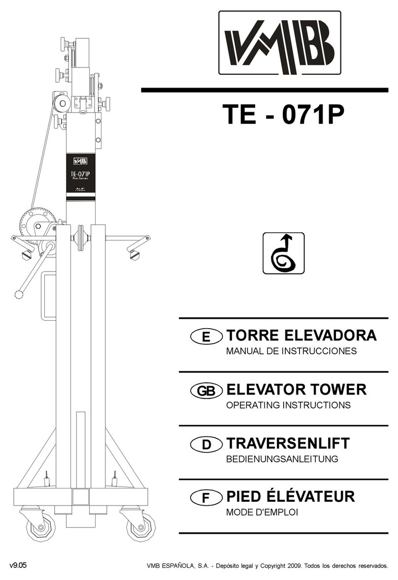
VMB TE - 071 PS User manual

ETORRE ELEVADORA
MANUALDE INSTRUCCIONES
ELEVATOR TOWER
GB OPERATING INSTRUCTIONS
DTRAVERSENLIFT
BEDIENUNGSANLEITUNG
FPIED ÉLÉVATEUR
MODE D'EMPLOI

TE-071PS
TE-071PB
Fabricante -Manufacturer -Hersteller -Fabricant
VMB EspañolaS.A.
Calle2-Pol. Ind. Picassent
E-46220 Picassent (VALENCIA) SPAIN
www.vmb.es -e-mail: contact@vmb.es
TORRE ELEVADORA
TOWERLIFT
TRAVERSENLIFT
PIED ÉLÉVATEUR
Estemanualde usuarioycatálogo anexode piezas de repuestoes propiedad de VMB Española,S.A.
Queda prohibida su reproduccion totaloparcialpor cualquier medioque latecnologíaactualpermita.
DepósitolegalyCopyright2006.Todos los derechos reservados.

DepósitolegalyCopyright2006.Todos los derechos reservados.
R
S
F
VT
TE-071P
MA
N2
W
N1
Q
PH
BT
M2
M3
M1

DepósitolegalyCopyright2006.Todos los derechos reservados.
Manualde instrucciones ESPAÑOL
CONTENIDO
1.Introducción
2.Datostécnicos
3.Medidasde seguridad
4.Instruccionesde uso
5.Mantenimiento
6.Garantia
7.Certificaciones
1. Introducción.
Estimadocliente,
Parafacilitarelmanejofiabledelatorreeleva-
doraTE-071PRO,hemoscreadoestemanual
deinstrucciones.
Leaatentamenteestemanualantesdeutilizar
latorre elevadora.
Observelosdatos técnicos.
LoselevadoresVMBsonsometidosa
durísimaspruebasparagarantizarlamáxima
fiabilidadyresistencia.LatorreTE-071Pestá
especialmenteconcebidaparatrabajarcon
totalfiabilidadyseguridad.Sumecanismode
elevación incorporaelsistemade seguridad
ALS «Auto-LockSecurity»exclusivodeVMB.
Estemanualdeberáestardisponibleper-
manentementejuntoalatorreelevadora.
Encasodenecesitar piezasderepuesto,di-
ríjaseasudistribuidorhabitual.Solamente de-
ben utilizarsepiezasde repuestooriginales.
Elusuarioperderátodossusderechosdega-
rantíasi incorporacualquierrepuestoque no
sea originalorealizacualquiermodificación
enlatorre.
Paracualquierconsultasobreelproducto,
debe indicarseelaño de construcción yel
númerodeserie.
2. Datostécnicos.
2.1- TorreelevadoramodeloTE-071PS/
TE-071PS.
2.2- Diseñadaparalevantarcargasensen-
tidoverticaladiferentesalturas,comosoporte
de aparatosde iluminación.
2.3- Carga máximaelevable:200 Kg.
2.4- Carga mínimaelevable:25 Kg.
2.5- Alturamáxima:5,35m.
2.6- Alturamínima:1,73m.
2.7- Superficiede labase:2,10 x2,10 m.
2.8- Pesode transporte:71 Kg.
2.9- Materialdeconstrucción:Perfildeacero
según DIN 2394.
2.10- Sistematelescópicode4tramosacciona-
dosporcable de aceroguiado porpoleasaca-
naladasconcojinetesderodamientoabolas.
2.11 - Cabrestante:500Kg.decargamáxima
confrenoautomáticoderetencióndelacarga.
Certificación CE yGS TÜV.
2.12-Cable:AcerosegúnDIN3060.Calidad
180 Kg/mm2resistentealatorsión.
2.13 - Diámetrodelcable:6mm.
2.14 - Exclusivosistemade fijación yseguri-
dadALS(Auto-LockSecurity),patentadopor
VMB, que fijaeimposibilitalacaída de la
cargaentodomomento.
2.15 - Platillosestabilizadoresajustablesen
laspatas,conapoyosantideslizantes de
caucho.
2.16 - Anclajede laspatasporgatillosde
seguridad.
2.17- Niveldeburbujaparaajustarlaposición
vertical de latorre.
2.18 - Protección antióxido yacabado por
zincadoelectrolítico(S)opoliesternegro(B).
2.19 - Ruedasdireccionables parafacilitar
eltransportede latorreen posición verticaly
plegada hastasuemplazamientode trabajo.

DepósitolegalyCopyright2006.Todos los derechos reservados.
Manualde instrucciones ESPAÑOL
3.NORMASDE SEGURIDAD. !
3.1- El elevadoresun elementoindustrial
diseñado paralaelevación de cargasen
sentido vertical, NUNCA sedebe utilizar
comoplataformaelevadorade personas.
3.2- Colocarelelevadorsóloensuperficies
durasyplanas,verificandoqueestáen
posición vertical.
Nuncautilicecuñasnielementosextraños
paraequilibrarelelevador.
3.5- Nosedebe sobrepasarlacapacidad
decargamáximaindicadaenlaetiquetade
característicasdelelevadoryen este
manualde instrucciones.
3.4- Nuncasedebe elevaruna carga sin
antesverificarqueestácorrectamente
apoyadaycentradaen lossoporteseleva-
doresadecuados,deformaqueelpesode
la carga sólo actúe en sentido vertical.
3.3- Comprobarquelaspatasestán
correctamentemontadasysujetasporsus
pasadoresretenedoresde seguridad.
Si seutilizan losestabilizadoreslaterales,
comprobarquequedan correctamente
insertadosyasegurados.
Kgs

DepósitolegalyCopyright2006.Todos los derechos reservados.
Manualde instrucciones ESPAÑOL
3.11- Nuncautilizarelelevadorsobreningu-
nasuperficiemóvilovehículo.
3.6- Siexisteposibilidaddevientofuerteo
en ráfagas, coloque elelevadoren suelo
firmeyasegúreloconlaayuda detirantes.
Nuncafijeun tirantesobreun vehículoni
cualquierotroelementoquepuedades-
plazarse.
3.10- Nuncasedebedesplazarelelevador
si ésteseencuentracon lacarga elevada.
Noesaconsejablerealizarningúntipode
movimiento,nitansiquierapequeñosajus-
tesde posicionamiento.
3.8- Tenga cuidadocon todo tipo de sa-
lientesporencimadelelevadorcomocor-
nisas,balcones,letrerosluminosos,etc...
Es muyimportanteevitarlapresenciade
cablespordebajodelaalturadetrabajodel
elevador.
3.7- No usarescalerasencimadel ele-
vadorniapoyarlasenélpararealizarningún
tipo de trabajo.
3.9- Nuncasepongadebajode lacargani
permitalapresenciade otraspersonasen
lazonade trabajodelelevador.

DepósitolegalyCopyright2006.Todos los derechos reservados.
Manualde instrucciones ESPAÑOL
3.12- Antesdeutilizarelelevador,verificar
elestadodelcable,éstenodebepresentar
roturade hilosoaplastamiento.Nousar
NUNCA cables defectuososyen casode
dudacambieelcable.Sóloutilicecablede
acerosegún DIN 3060.Calidad 180 Kg/
mm2resistentealatorsión.
3.16 - Paraeltransporte delelevadorhay
quebajartodoslostramos.
3.15- Noengrasarnilubricarelmecanismo
de freno delcabrestante.Losdiscosde
freno,han sido engrasadoscon una grasa
especialresistentealcalorylapresión.
Nodeben serutilizadosotrosproductos
paraevitarinfluirnegativamenteenelfun-
cionamientodelfreno.
3.14 - La carga mínimaparaun funciona-
mientodelfrenosinproblemasesde25Kg.
Sinestacargamínimaelfrenonoactuará.
3.13- Nodesmontarnuncalamaniveladel
cabrestante(W)si elelevadorestácon
cargayelevado.
3.17-Solamentedebenutilizarsepiezasde
repuestoVMB originales.
ORIGINAL
-25

DepósitolegalyCopyright2006.Todos los derechos reservados.
Manualde instrucciones ESPAÑOL
4.Instruccionesdeuso.
4.1 - Colocar la torre elevadora apoyada en las
ruedas direccionables de transporte (T)sobre
unasuperficieplanayfirmeen su emplazamiento
de trabajo.
4.2 - Sacar las patas (P)de su soporte para
transporte (S)einsertarlas afondo en sus aloja-
mientos de trabajo(V)comprobando que quedan
sujetas por los gatillos retenedores de seguridad.
(R)
4.3- Ajustarlaposiciónverticaldelatorremedian-
telosplatillosdeapoyoregulables(Q)girandolas
manivelas (H)enelsentidonecesariopara lo-
grarquelaburbujadelindicador de nivel (F)
quede centrada en el círculo.
4.4 - Colocar la carga aelevar sobre la torre
medianteun soporte adecuado segúnel caso, de
forma que el peso de la carga sólo actúe en
sentido vertical. La carga deberá ser como míni-
mo de 25 Kg.
4.5 - Elevar:
Girarlamaniveladelcabrestante(W)en
elsentidodelasagujasdelreloj(N
1
),
elevandolacargahastalaposicióndeseada,
comprobandoquelosgatillosdelsistemaAuto-
Lockvanenclavándose,fijando
automáticamentelostramos.
4.6-Descenso:
Liberarelgatillodeseguridad(M1).Para
liberarlosgatillosdeseguridadhayqueelevar
ligeramentelacarga con elcabrestantepara
soltarlos. Enlaposición normalde trabajo,el
pesode lacarga impide liberarlosgatillos.
Unavezdesbloqueadoelgatillodeseguridad
(M1),girarlamaniveladelcabrestanteensen-
tido contrarioalasagujasdelreloj(N2)hasta
que descendiendo lacarga,quede bajado al
máximoeltramo 1.Liberarelgatillo(M2)y
seguirbajandolatorrehastaqueéstesegundo
tramobajealmáximo.Desbloquearelgatillo
(M3)yseguir bajando lacarga hastaque la
torrequedecompletamenteplegadaasualtu-
ramínima.
Latorrepuededejarseencualquierpo-
sición intermedia que senecesitedel mis-
momodo que alsubir lacarga.
4.7- Paratransportarlatorreesnecesario
plegarlabajandocompletamentelostramosy
fijarloscon elsoportede transporte BT.Des-
montarlaspatasliberando losgatillosde re-
tención ycolocarlasen suposición de trans-
porte(S).

DepósitolegalyCopyright2006.Todos los derechos reservados.
Manualde instrucciones ESPAÑOL
5. Mantenimiento.
5.1- Comprobarperiódicamenteelestado
delcable.Siun cable presentaroturade
hilosoaplastamiento,debe sersustituido
inmediatamenteporotronuevo.Noutilizarla
torreelevadoracon cablesen malestado.
Utilizarsólamentecablede aceroDIN
3060 resistentealatorsión.
5.2- La torreelevadorasesuministra
completamenteengrasada defábrica.
Noobstante, serecomiendaengrasar
periódicamente segúnel uso,lacorona
dentada delcabrestante,loscojinetesdel
arbol deaccionamientoy el buje,la rosca
de la manivelaylostramos.
ATENCION:
Noengrasarnilubricarelmecanismo
delfreno.
Losdiscosde freno,han sido engrasa-
dosconunagrasaespecialresistentealcalor
ylapresión.Nodeben serutilizadosotros
productosparaevitarinfluirnegativamenteen
elfuncionamientodelfreno.
Noesnecesarioengrasarlosdiscosde
freno.
5.3- La torreelevadoraTE-071P, debe ser
comprobadaporunexpertocomomínimouna
vezalañodeacuerdoconsuutilización.
5.4- Sólamentedeben utilizarsepiezasde
repuestooriginalesparagarantizarunacon-
tinuadaseguridadde uso.
El usuariopierde todoslosderechosde
garantía,siincorporaotrosrepuestosqueno
seanoriginalesollevaacabocualquiermodi-
ficaciónenelproducto.
5.5- Para solicitarcualquierpiezade re-
puesto,debe indicarsesunúmerode refe-
rencia,que figuraen lashojasfinalesde des-
piecedeestemanual.
7. Certificaciones
-
Directivade maquinas:
89/392/CE y98/37/CE
-BGV C1(GUV-VC1)/BGG 912 (GUV-G912)
6.Garantía.
Elperiododegarantíadeestatorreelevadora
esdedosaños,apartirdelafechadecompra.
VMB Española,S. A. secompromete,a
partir de estafecha yduranteelperiodo de
garantía,aeliminartodoslosfallosquepue-
dan aparecerproducidospordefectosde los
materialesode lafabricación.
Noestánincluidosenlagarantíalosda-
ñosproducidosporunusoindebido,modifi-
cacionesdelproducto,manipulación porter-
cerososiniestronaturaloaccidental.

DepósitolegalyCopyright2006.Todos los derechos reservados.
Operatinginstructions ENGLISH
CONTENTS
1.Introduction.
2.Technicalinformation.
3.Safety precautions.
4.Operation.
5.Maintenance.
6.Guarantee
7.Certificaciones
1. Introduction.
Dearcustomer,
Inordertomakeareliableoperating ofthe
elevatortowerTE-071Ppossible,wehave
created this operating instruction.
Beforeuse,you arerequired toread the
operating instructions.
Pleasenotethe technicaldata.
Ourproducts undergo veryrigoroustesting
understrictconditionsandtheyaremonitored
continuouslyduringthemanufacturing
process.
Inordertoguarantee theliftfunction and
safety,theoriginalpartsofthemanufacturer's
designmustbeused.Ifanypartsotherthan
thoseof the manufacturerareused,orthe
productismodifiedinanyway,theuserforfeits
allwarrantyrightstoclaim.
Wereservetherighttomodify design and
performancewithoutpriornoticewhen
contacting uswithqueriesorordering
spareparts the model type,yearof
manufacture, andserialnumberareto
be quoted.
2. Technical information.
2.1- ElevatortowerTE-071PS /TE-071PB.
2.2- Designed tolift loadsvertically up to
different heightsassupportforsetsof
illumination.
2.3- Maximumload :200 Kg.
2.4- Minimumload :25 Kg.
2.5- Maximumheight:5,35 m.
2.6- Minimumheight:1,73 m.
2.7- Area of base : 2,10 x 2,10 m.
2.8- Transport weight : 71 Kg.
2.9- Constructionmaterial:SteelprofilesDIN
2394.
2.10- Fourprofilestelescopicsystemoperated
bycableofsteeland guided bychannelled
steelpulleys withball bearings.
2.11 - Winch:500 Kg.ofmaximumload with
automaticbraketostoptheload.
Certification CE and GS TÜV.
2.12-Cable:SteelDIN3060.Quality180Kg/
mm2.Twisting -resistant.
2.13 - Cablediameter:6mm.
2.14 - Exclusive ALS system ( Auto-Lock
Security).
2.15 - Adjustablestabilizing disc feetinthe
legswithrubernon slipsupports.
2.16 - Anchorofthe legsbysafety catches.
2.17- Spiritleveltoadjusttheverticallityofthe
tower.
2.18- Antirustprotection and electrolitic
cadmiated (S)orblack polyester(B).
2.19 - Swivelwheels forthe verticaltransport
ofthe towertoits working location when
folded.

DepósitolegalyCopyright2006.Todos los derechos reservados.
Operatinginstructions ENGLISH
3. SAFETY PRECAUTIONS. !
Kgs
3.1-TheTE-071Pisamachinedesignedto
elevateloadsupwardsinaverticaldirection,
NEVER shouldit be used asaplatform to
elevatepeople.
3.2- Onlyplacetheliftonhard,flatsurfaces
alwayscheckingthatitisinaverticalposition
byusingthebubblelevelindicator(F)found
on the basesection.Adjust the outrigger
stabilisers(Q)byturningthecrankstolevel
if necessary. NEVER usewedgesorother
foreignobjectstobringthelifttoequilibrium.
3.5- The maximumload indicated on the
characteristics labeland the instructions
manualshouldnotbeexceeded
3.4- NEVERshouldtheliftbeusedtoelevate
aloadthathasnotbeenproperlychecked.It
isnecessarytoverifythattheloadiscorrectly
supported and centred on the appropriate
liftsupportsothattheweightoftheloadwill
onlyelevateinaverticaldirection.
3.3 - Check thatthe outriggers are placed
and set-up correctly using the pinssafety
system.

DepósitolegalyCopyright2006.Todos los derechos reservados.
Operatinginstructions ENGLISH
3.11- NEVERusetheliftonavehicleorany
othermobilesurface.
3.6- Ifthereisapossibilityofstrongwindsor
gusts,placetheliftonthegroundfirmlyand
secureit withthe useofstraps. NEVER
attachastraptoavehicleoranyotherobject
thatcanpossiblybemoved.
3.10- NEVERmovetheliftwhilstitiscarrying
aload.Itisnotadvisabletocarryoutanytype
ofmovementeven smallpositional
adjustments.
3.9- NEVERallowanyteammemberbelow
theloadoranybodyelseintheliftsoperating
zone.
3.8- Takecarewithallobstaclesabovethe
liftanditsextensionzonesuchascornices,
balconies, and luminoussignboards. It is
very importanttoavoidthe presenceofall
typesofcablesbelowtheextendedlift.
3.7- Donotusestepladdersontheliftoruse
itasasupportforthem.

DepósitolegalyCopyright2006.Todos los derechos reservados.
ORIGINAL
-25
3.12- Beforeusingthelift,checkthestateof
the cable.The cableshouldnotcontain
brokenthreadsorshowanysignsofcrushed/
flattened areas. NEVER usefaulty cables,
always change themif there is anydoubt.
Onlyusesteelcablesreference:DIN3060.
Quality:180KG/mmandtorsionresistant.
3.16 - All sectionsmust be lowered during
transportation.
3.15- Donotgreaseorlubricatethewinch’s
breakingmechanism.Thebrakediskshave
beengreasedwithaspecial heatand
pressureresistantsolution.Otherproducts
shouldnotbeusedtoavoidnegativeeffects
regardingthebrakingmechanism.
3.14- Theminimumloadtoavoidproblems
regardingthebreakingmechanismis25KG.
Withoutthisloadthebrakewillnotwork.
3.13 - NEVER takeapart the crankofthe
winchwhen the lift is carrying aload or
extended.
3.17-Onlyoriginalreplacementpartsshould
beused.
Operatinginstructions ENGLISH

DepósitolegalyCopyright2006.Todos los derechos reservados.
Operatinginstructions ENGLISH
4. Operation.
4.1- Inordertoplacethe elevatortowerin
theirworkinglocation,putthe towerleaned in
their transport wheels (T)on ahardand level
surface.
4.2- Getonthelegs(P)oftheirsupportforthe
transport (S)and insert themintheir working
lodging(V)verifying that theyaretightly
fastened bythe safety catches(R).
4.3- Adjusttheverticalpositionofthetowerby
meansofthe disc feetsupports (Q)rotating
the hand crank(H)inthe necessary direction
tomanagethatthebubbleofthespiritlevel(F)
stays centred inthe circle.
4.4- Puttheloadontopofthetowerusingthe
suitablesupport, inordertomakework the
weightoftheloadonlyintheverticaldirection.
The minimumload must be 25 Kg.
4.5- Lifting:
Elevatethetowerrotatingthehandcrank
ofthewinch(W)clockwise(N1),liftingtheload
uptodesiredheight.
4.6- Lowering:
The manoeuvreoflowering is obtained
bythe oppositeway. Lift the blockade on the
safetycatch(M3)androtatethehandcrankof
thewinchinacounterclockwise(N2)lowering
the load until thatthe thirdprofilewouldbe
completelyfolded.
Lifttheblockadeonthesafetycatch(M2)
andcontinue loweringthetoweruntil thatthis
secondprofilewouldbecompletelyfolded.
Lifttheblockadeonthesafetycatch(M1)and
continueloweringthe load untilthatthetower
wouldbecompletelyfoldeddowntoitsminimum
height.
Thetowercanbeleftinanyintermediate
positionwichwouldbenecessary,thesameas
liftingtheload.
4.7-Forthetransportofthetowerisnecessary
to foldthe towerloweringcompletelyallthe
profiles,blockadingthemwiththesafety
catches(BT).Getout thelegsliftingthe
blockadeonthecatchesandputthemintheir
transportlodging(S).

DepósitolegalyCopyright2006.Todos los derechos reservados.
Operatinginstructions ENGLISH
5.Maintenance.
5.1- The cableis tobe regulary checked for
wear(ie:kinks,singlestrundbreakage).Faulty
cablesmust be replaced immediately. Donot
usethe elevatortowerwithfaulty cables.
Only usehandlecablesDIN 3060.
5.2- Theelevatortowerhasbeenlubricatedin
theworkshop.Itisneverthelessrecommended
thatoilisregularyappliedtothegeardrive,the
bearing busheson the driveshaft and tothe
drumhub,the thread ofthe handleand the
profilesofthe tower.
ATTENTION:
Donotapplyoilorgreasetothebrake
mechanism.
Thebrakewashershavebeen
pregreasedwithanspecial warmth and
pressureresistantgrease.Donotuseother
greasesasthis will effect the winchbrake
performance.
It is notnecessary greasing the brake
washers.
5.3- The elevatortowerTE-071Pmust be
inspected bytrained personnelatleast once
annually.
5.4- Inordertomaintainthis guarantee of
functionand safety, original partsofthe
manufacturer'sdesignmustbeused.
Theuserforfeitsallrightstoclaimifparts
otherthanthoseofthemanufacturerareusedor
modifiestheproductinanyotherway.
5.5- Whenanysparepartwouldberequired,it
isnecessary toindicateitsreferencenumber,
wichis included inthe spareparts ofthis ma-
nual.
7. Certifications
-
ECMachineryDirective
89/392/ECC and 98/37/ECC
-BGV C1(GUV-VC1)/BGG 912(GUV-G912)
6. Guarantee.
If the during the guarantee period becauseof
poorworkmanshiporfaulty materials VMB
Española,S.A. will repair orreplaceit.
The guarantee period forEurope is at2
years.
The guarantee doesnotcoverdamage
causedbyimproperuse,wear andtear
unauthorisedrepairs.Theguaranteedoesnot
coverconsumablesordefectsthathaveonlya
negligibleeffectonthevalueoroperationofthe
elevatortower.

DepósitolegalyCopyright2006.Todos los derechos reservados.
Bedienungsanleitung DEUTSCH
Inhaltsverzeichnis
1.Einführung.
2. Technische Daten.
3.Sicherheitsmaßnahmen.
4.Bedienungsanleitung.
5.Wartung.
6.Garantie.
7.Zertifikat.
1. Einführung.
SehrgeehrteDamenundHerren,
dievorliegende Betriebsanleitung wurde mit
demZweck erstellt,einezuverlässige
Bedienung desTE-071P Hebeturmszu
ermöglichen.LesenSiebittedie
BetriebsanleitungvorInbetriebnahmesorgfältig
durch.
BittebeachtenSieauchdietechnischeDaten.
UnsereProdukteunterliegenstrengsten
PrüfungenundKontrollenbeiderFertigung.
Es sind ausschließlichOriginal-Ersatzteilezu
verwenden.Fürden Anwenderwerden alle
Gewährleistungsansprücheaufgehoben,wenn
erNicht-Original-Ersatzeileverwendetbzw.
ÄnderungenamProduktselbstvormimmt.
2. Technische daten.
2.1- Hebeturm,TypTE-071PS/TE-071PB.
2.2- DasGerätist zumsenkrechten Heben
vonLasten,wie aufverschiede Höhen,
konzipiert worden.
2.3- Zulässige Hubkraft : 200 Kg.
2.4 - Mindesthublast :25 Kg.
2.5 - Zulässige Hubhöhe :5,35 m.
2.6- Mindeshubhöhe :1,73 m.
2.7 - Grundplattenfläche :2,10 x2,10 m.
2.8- Transportgewicht : 71 Kg.
2.9- Werkstoff:StahlprofilnachDIN2394.
2.10 - TeleskopierbaresSystem, bestehend
ausvier, von einemübergenufeteRollen mit
WälzlagerngeführtenStahlseilangetriebenen
Abschnitten.
2.11- DieWinde,miteinerzulässigenHublast
von 500 Kg, istmit einerautomatischen
Lasthaltebremseausgestattet.
CEundGS TÜV.
2.12-Seil:ausStahlnachDIN3060.Güte180
Kg/mm2verwindungssteif.
2.13 - Seildurchmesser:6mm.
2.14 - ExklusiveALSSystem( Auto-Lock
Security).
2.15 - Auslegermit verstellbaren Spindeln
und rutschfesten Gummifüßen.
2.16 - Verankerung derAuslegerüber
Sicherheitsklinken.
2.17- Wasserwaage zumEinstellen der
senkrechten Turmlage.
2.18- KorrosionsschutzundVeredelungdurch
elektrolytsche Cadmierung.
2.19 - TransportrollenzumBewegendes
Turmsbeisenkrechterundeingefahrener
Stellung zurArbeitsstelle.

DepósitolegalyCopyright2006.Todos los derechos reservados.
3.SICHERHEITSMAßNAHMEN. !
3.1- DerTE –071Pwurde konzipiert zum
Heben und Senken von vertikalen Lasten.
NutzenSieIhnniemalszurBeförderungvon
Personen.
3.2- AchtenSiedarauf,dasderTL–Tower
auffestem,geradenUntergrundsteht.Und
vergewissernSiesichmit Hilfeder
Wasserwaage (F), dass ereine vertikale
PositionzumBodeneingenommenhat.Bei
Bedarf mittels desStelltellers (Q) durch
DrehenderSpindelkurbel (H) die
entsprechendeTunlageeinstellen.
3.5- Diezulässige Höchstlast, dieSieauf
denTypenschild,welchesiein der
Bedienungsanleitung finden,darf niemals
überschrittenwerden
3.4- NiemalssolltenSieeineungesicherte
Ladungheben.VergewissernSiesich
immer, dasdieLadung zentriert aufder
GabelaufliegtundnurinvertikalerRichtung
hebt!
3.3- Vergewissern Siesich,dass die
Auslegerrichtigeingestecktsindundnutzen
SiedieRastbolzenzumfeststellen!
Bedienungsanleitung DEUTSCH
Kgs

DepósitolegalyCopyright2006.Todos los derechos reservados.
3.11- EsistnichtgestattetdenLiftaufeinem
Fahrzeug mit einen mobilen Unterbau zu
installieren!
3.6- BeiFreiluftanwendungendenTurmauf
festen Boden stellen und mittels Seilanker
gegenWindbelastungsichern.Niemalsan
FahrzeugendieAbspannungenbefestigen
oderan Gegenständen,dieausweichen
könnten.
3.10 - Bewegen Sieden Lift niemals unter
Belastung.
3.8- Achten SieaufalleGegenstände im
oberen HubbereichdesLiftes. Achten Sie
aufBalkone,Leuchtschriftenundbesonders
aufstromführendeKabel.
3.7- Stellen Sieniemals Leiternan den
Tower.
Bedienungsanleitung DEUTSCH
3.9- Halten Siesichniemals während des
Hebensund SenkensinGefahrenbereich
auf.

DepósitolegalyCopyright2006.Todos los derechos reservados.
3.12 - VorGebrauchSeilzustand
kontrollieren.DasSeildarfkeineSeilbrüche
oderQuetschungen aufweisen.Es dürfen
aufkeinemFall Seile ineinemschlechten
Zustandverwendetwerden.
3.16 - AlleAngebauten Teilesind fürden
Transporteinzufahren.
3.15- ÖlenoderFettenderFallbremsen ist
zuunterlassen, da diesemit einemDruck
und Hitzebeständigen Materialbearbeitet
wurden.AndereWerkstoffeführen inder
HandhabungzunegativenEffekten.
3.14- DiemaximaleBelastungzur
ÜberprüfungderSicherungenist25kg.Ohne
BelastungistdieÜberprüfungnichtmöglich.
3.13 - Niemals dieWinde,oderTeileder
WindeunterBelastungdemontieren.
3.17- EssindausschließlichOriginal
Ersatzteilezuverwenden.FürdenAnwender
werdenalle Gewährleistungsansprüche
aufgehoben,wennnichtOriginalErsatzteile
verendetbzw.Änderungen an Produkten
vorgenommenwerden.
Bedienungsanleitung DEUTSCH
ORIGINAL
-25

DepósitolegalyCopyright2006.Todos los derechos reservados.
Bedienungsanleitung DEUTSCH
4.Bedienungsanleitung.
4.1- Den Hebeturm aufden Transportrollen
(T)abgestütztaufeineebeneundfesteFläche
an derArbeitsstelleaufstellen.
4.2 - DieAusleger(P)ausder
Transporhalterung (S)herausnehmen und in
derenArbeitsaufnahmen(V)volleinschieben.
Dabeiachten Siebittedarauf, daßsiemittels
derSicherheitsbolzen (R)befestigtsind.
4.3- Die senkrechteTurmlage überdie
verstellbaren Spindel(Q)durchDrehen der
kurbel(H)inentsprechenderRichtung zum
Zentrieren derWasserwaagenblase(F)an
derKreismitteeinstellen.
4.4- Diezuhebende Last aufdemTurm
mittelseinesgeeignetenTrägerssoaufstellen,
daßdasLastgewichtnursenkrechtwirkt. Die
Mindestlast muß25 Kg.betragen.
4.5- Heben:
DenTurmdurchDrehenderWindekurbel
(W)imUhrzeigersinn(N1),aufdiegewünschte
Höhebringen.PrüfenSiebitte,dassdieBolzen
desAuto-Lock-SystemsinSchaltpositionsind
undeinrasten,sodassdieAbschnitte
automatischfixiertwerden.
4.6-Senken:
Den Sicherheitsbolzen (M1)entriegeln.
UmdieSicherheitsbolzenzuentsperren,muß
mandieLastmitderWindeleichtanheben.In
dernormalen Arbeitsposition verhindert das
LastgewichtdasEntriegelnderBolzen.Nach
demEntriegelndesSicherheitsbolzen (M1),
dieKurbelderWindegegendenUhrzeigersinn
(N2)drehen bisbeim Senken derLast
Turmabschnitt1vollheruntergefahrenist.
DenBolzen(M2)entriegelnundderTurmweiter
nachuntensenkenbisAbschnitt 2voll
heruntergefahrenist.
Bolzen (M3)entriegelnund dieLast weiter
senkenbisderHeberturmvollkommenbiszur
Mindesthöheheruntergefahrenist.
4.7- ZumTransport sind dieLiftsegmente
einzufahren,wobeidieEinzelsegmentemittels
derTransportsicherungBTfixiertwerden.Die
Ausleger entsperren und diesein ihre
Transportstellung(S)bringen.
This manual suits for next models
1
Table of contents
Languages:
Other VMB Camera Accessories manuals
Popular Camera Accessories manuals by other brands
Ferno
Ferno Tripod Series user manual

Gates Underwater Products
Gates Underwater Products MINI LF Setup, use and care guide

Sanyo
Sanyo Twicell HR-3URS Specifications

Focus Ebhancements
Focus Ebhancements FS-H200 user guide
Olympus
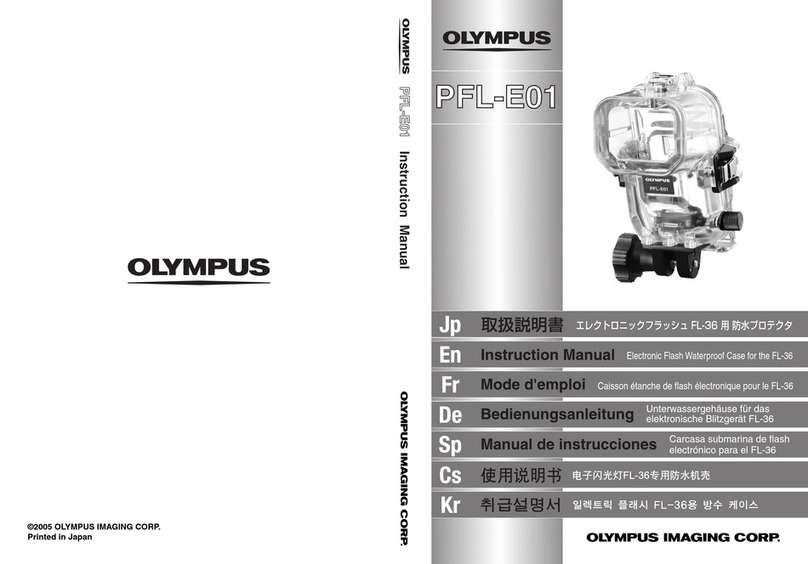
Olympus PFL-E01 instruction manual

Panasonic
Panasonic DMW-MCTZ20E operating instructions
