VOGELS PPL 2500 User manual

This document is property of Vogel’s Products BV
Any distribution, reproduction, copying or publication of this document is prohibited.
INSTALLATION MANUAL
PROJECTOR LIFT
PPL 2500
MOUIN_PPL2500_V3

2
This document is property of Vogel’s Products BV
Any distribution, reproduction, copying or publication of this document is prohibited.
Thank you for purchasing the new Projector Lift.
The PPL 2500 is supplied with a set of components and accessories that make it suitable for installation
for the majority of standard AV applications, but note must be made of the restrictions that apply to the
weight capability of this unit and not exceeded.
Before installing the lift, please read the following instructions carefully.
Please, always keep these instructions so that anyone can read them when needed.
The manufacturer does not takes responsibility for any damage to property or personal injury if the
projector lift is used outside or recommended specifications or in case of incorrect installation.
INSTALLATION OF PPL 2500 PROJECTOR LIFT HAS TO BE CARRIED OUT FROM QUALIFIED PERSONNEL
ONLY.
Before installing the projector lift, please read the following instructions carefully:
The projector lift must be used indoors only.
It is forbidden to stay under the lift and within a range of 3 meter from the lift.
Never connect more than one lift motor to the same switcher. Use the supplied switcher only.
In case of maintenance, unplug the power supply.
Please confirm that your projected image width will fit your screen from your proposed
mounting location prior to installation.
Incorrect use of the lift, including exceeding the maximum lifting weight, will be dangerous .
The manufacturer does not take responsibility for any damage or property or personal injury if
the lift is used outside of recommended specifications.
This product uses a 230V AC Motor. Do not attempt to service the motor. Incorrect servicing
could lead to risk of electric shock.
For any repairing, please contact directly the dealer you purchased the unit from.
Check at least once a year that the screws of the steel cables are well tightened and that the
steel cables are in good conditions. In case they have signs of usage or damages, replace them
promptly with the original ones supplied by the manufacturer.
Check every 6 months that screws, wall plugs and brackets are in good conditions and well
tightened.
MOUIN_PPL2500_V3

3
This document is property of Vogel’s Products BV
Any distribution, reproduction, copying or publication of this document is prohibited.
SUPPLIED EQUIPMENT LIST
When you open the packaging, please CHECK that it contains ALL the components below listed. In case
one or more components are missed, please refer to the dealer you purchased the product from.
A) 1 MECHANIC PROJECTOR LIFT
B) 4 METAL BRACKETS FOR CEILING MOUNTING
C) 16 SOCKET HEAD SCREWS 8X20
D) 16 M8 WASHERS
E) 16 M8 CROWNED NUTS
F) RF REMOTE CONTROL
G) INSTALLATION MANUAL
A
B
F
C D E
MOUIN_PPL2500_V3

4
This document is property of Vogel’s Products BV
Any distribution, reproduction, copying or publication of this document is prohibited.
CEILING MOUNTING
- In order to mount the four metal brackets shown on Fig. “B” above on the upper aluminium frame of
the PPL 2500, please use screws, washers and crowned nuts mentioned on “C, D, E” of the supplied
equipment list; put inside the groove of the aluminium frame the crowned nut as shown on Fig. 1A;
connect the ceiling bracket to the profile by the socket head screws and the crowned nuts, move the
ceiling bracket along the profile in order to position it where needed (Fig. 1B); now firmly tighten the
screws of the four brackets.
- Note: the four ceiling mounting brackets can be mounted in two different ways on the upper
frame of the lift:
1- Brackets mounted towards outside – Fig. 8-A – page 10
2- Brackets mounted towards inside – Fig. 8-B – page 10
- Once the four brackets have been mounted on the upper frame of the lift, mount the lift to the
ceiling using plugs, anchors or screws (not supplied) specific for the type of material to drill.
During the installation pay attention that the lift is perfectly levelled both on the width and on the
depth. (See Fig. 2).
Fig. 1B
Fig. 1A
Fig. 2
MOUIN_PPL2500_V3

5
This document is property of Vogel’s Products BV
Any distribution, reproduction, copying or publication of this document is prohibited.
ELECTRIC CONNECTION
- The motor has the possibility to be controlled via the supplied handheld RF remote control or via
wired low voltage contact closures.
- The motor has a six-core power cable. Never connect the mains to the wires White, White-Black,
White-Orange.
- Once the lift is mounted to the ceiling, connect the wires brown, blue and yellow/green to the mains,
following the scheme shown in Fig. 3A;
- The lift is supplied with a safety mechanism (Fig. 3B) with a double security system: first - this is a
mechanic safety system that prevents the steel cable to unroll when the speed has reached 50 rpm,
second – this is an electrical security system that disconnect the electrical connection of the motor if
the force driven on the steel cable, caused by the falling down, is more than 503 Nm.
FIXING THE PROJECTOR TO LIFT
- Roll down the PPL 2500 by pushing ▼button on on the remote control (Fig. 7A) in order to lower the
lift till the lower end-stop (SERVICE mode), preset in the factory at 2,5 mt. ca. In case you wish to
modify the lower end-stop (SERVICE mode), please refer to instructions at page 8 and 9.
In order to fix the projector under the lift, position the splines of the three profiles of the lower lift
frame, to match the anchoring points on the projector (Fig. 4A).
Unloose the four screws as shown on Fig. 4B and position the three profiles where needed (Fig. 4C).
Once you have aligned the splines of the profiles with the anchoring points on the projector tighten
the screws and the bolts of the profiles following a cross scheme.
Repeat this step until all the screws on the three profiles will be very well tightened.
Insert the screws for mounting the projector in the milling of the profiles (milling depth 10 mm) and
tighten the screws in the anchoring points of your projector.
Fig. 3B
Fig. 3A
MOUIN_PPL2500_V3

6
This document is property of Vogel’s Products BV
Any distribution, reproduction, copying or publication of this document is prohibited.
ADJUSTMENT OF PITCHING AND ROLLING OF THE PROJECTOR
Projectors have not a regular distribution of the weight on their surface but tent to have unbalancing
caused by the lamp, by the optical system and so on.
Unbalancing could lead to either a right and left rolling or a pitching of the lower lift frame - projector.
The PPL 2500 have been developed in order to solve these problems and allow to adjust the lift in order
to get a perfect balance of the entire lifting system.
In order to adjust PITCHING, please move the motor along the profile where the motor itself is fixed, by
loosen the screws as shown on Fig. 5A and 5B and move the motor left or right until the lower frame will
be perfectly balanced (Fig. 5C).
Please proceed, with this step, after having laid the projector mounted on the frame on a support
surface, in order to lighten the motor from the weight.
Now loose the screws on Fig. 5D and by using a rubber hammer, move the profile of Fig. 5E, left or right
in order that the steel cables are perpendicular both on the upper part and on the lower part of the lift
(see Fig. 5C. At the end of the adjustment tighten the screws firmly (Fig. 5D).
Fig. 4A
Fig. 4B
Fig. 4C
MOUIN_PPL2500_V3
Fig. 5A
Fig. 5B
Fig. 5C

7
This document is property of Vogel’s Products BV
Any distribution, reproduction, copying or publication of this document is prohibited.
In order to adjust ROLLING, please tighten or unloose the nuts that act on the tension of the steel
cables. (Fig. 6A)
Fig. 6A
Fig. 5D
Fig. 5E
Fig. 5F
MOUIN_PPL2500_V3

8
This document is property of Vogel’s Products BV
Any distribution, reproduction, copying or publication of this document is prohibited.
ADJUSTMENT OF THE END STOPS
PLEASE READ CAREFULLY
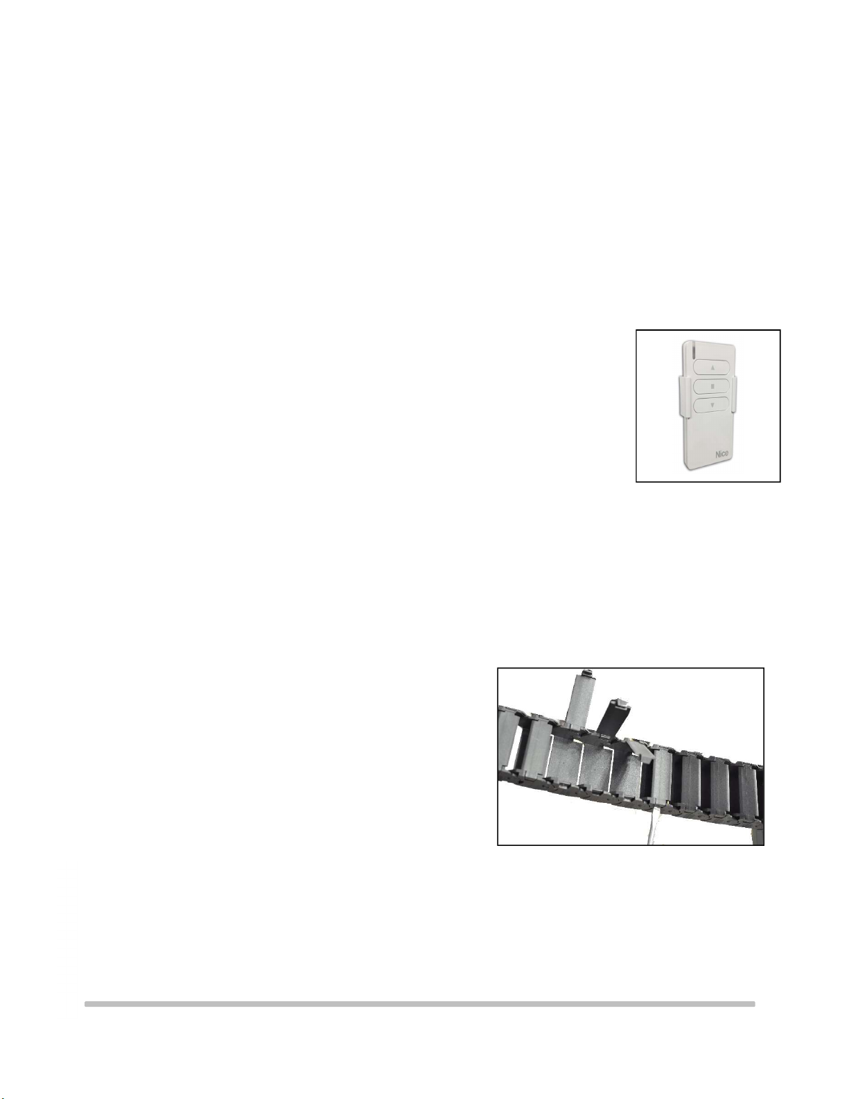
The PPL 2500 motorized lift is supplied with a remote control that allows to set three positions:
1. CLOSED LIFT: pre-set by the factory, in closed upper position. WARNING: in case the installer
needs to modify this end-stop, it is only allowed to lower the upper end-stop position. Do not
try to raise the upper end-stop because this will cause severe damages to the product and this
operation will invalidate the warranty.
2. PROJECTION MODE: intermediate stop position, not pre-set by the factory.
3. SERVICE MODE: lower end-stop position, pre-set by the factory at 2,5 mt. circa.
How to modify the end-stops:
A- SETTING OF THE LOWER END STOP (SERVICE MODE)
- Lower down the lift till half stroke, pressing the remote control button ▼ and stop it with
button ◼.
- Press the button ◼ (for 5 secs) till the motor swivels 2 times.
- Press again the button ◼ (for 5 sec) till the motor swivels 4 times.
- Press the button ▼ (for 5 sec) till the motor swivels 2 times.
- Press and hold the buttons ▼ or ▲ in order to the reach the desired position of the lift.
Warning: during this programming operation you have to keep the buttons ▼ or ▲ pressed in
order to reach the desired position.
- Once this position is reached, in order to memorize it press the button ◼ (for 5 sec) till the
motor swivels 3 times.
B- SETTING OF THE UPPER END-STOP
WARNING: in case the installer needs to modify this end-stop, it is ONLY allowed to lower the upper
end-stop position. Do not try to raise the upper end-stop because this will cause severe damages to
the product and this operation will invalidate the warranty.
- Lower down the lift till half stroke, pressing the remote control button ▼ and stop it with
button ◼.
- Press the button ◼ (for 5 secs) till the motor swivels 2 times.
- Press again the button ◼ (for 5 sec) till the motor swivels 4 times.
- Press the button ▲ (for 5 sec) till the motor swivels 2 times.
- Press and hold the buttons ▼ or ▲in order to the reach the desired position of the lift.
Warning: during this programming operation you have to keep the buttons ▼ or ▲ pressed in
order to reach the desired position.
- Once this position is reached, in order to memorize it press the button ◼ (for 5 sec) till the
motor swivels 3 times.
MOUIN_PPL2500_V3

9
This document is property of Vogel’s Products BV
Any distribution, reproduction, copying or publication of this document is prohibited.
C- SETTING OF THE INTERMEDIATE STOP (PROJECTION MODE)
- Lower down the lift till half stroke, pressing the remote control button ▼ and stop it with
button ◼.
- Press the button ◼ (for 5 secs) till the motor swivels 2 times.
- Press again the button ◼ (for 5 sec) till the motor swivels 4 times.
- Press simultaneously the buttons ▲+▼ (for 5 sec) till the motor swivels 2 times.
- Press and hold the buttons ▼ or ▲ in order to the reach the desired position of the lift.
Warning: during this programming operation you have to keep the buttons ▼ or ▲ pressed in
order to reach the desired position.
- Once this position is reached, in order to memorize it press the button ◼ (for 5 sec) till the
motor swivels 3 times.
D- USE OF THE REMOTE CONTROL
- Press the button ▼ in order to reach the lower-end stop (SERVICE mode).
- Press the button ▲ in order to reach the upper-end stop.
- Press simultaneously the buttons ▲+▼ in order to reach the intermediate
stop (PROJECTION mode).
E- CONNECTION OF LOW VOLTAGE CONTACTS TO REACH THE DIFFERENT END-STOPS.
- Close the connection, for at least 1 second, between the white-black and white-orange wires in order to
reach the LOWER end stop (SERVICE mode).
- Close the connection, for at least 1 second, between the white-black and white wires in order to reach
the UPPER end stop.
- Close the connection, for at least 1 second, simultaneously between the white-black, white-orange and
white wires in order to reach the INTERMEDIATE stop (PROJECTION mode).
The projector lift includes a cable management system.
In order to fit in the power and signal cables of the projector
Move the lift in the lower end stop position (SERVICE MODE),
and open the small doors, as shown in Fig. 7B.
Fig. 7B
MOUIN_PPL2500_V3
Fig. 7A

10
This document is property of Vogel’s Products BV
Any distribution, reproduction, copying or publication of this document is prohibited.
TECHNICAL DETAILS
Power supply 230 V, 50 HZ
Consumption 360 Watt
Torque 80 Nm
Motor speed 12 rpm
Roll up/ down speed 17 sec./ meter
Thermal stop after 4 minutes of operation
Net weight lift 78 kg
Maximum load of the projector 95 kg
Dimensions closed 790x716x890 (WxHxD in mm.)
Dimensions opened 790x716x890 (WxHxD in mm.
Fig. 8
Top
view
Bottom view
Side view
MOUIN_PPL2500_V3
Table of contents
Other VOGELS Lifting System manuals
Popular Lifting System manuals by other brands

Blue Giant
Blue Giant BLUE GENIUS TL85 Series Installation & owner's manual

TOOLCRAFT
TOOLCRAFT 2489541 operating instructions

Skyjack
Skyjack SJ12 Operation manual

Challenger Lifts
Challenger Lifts SA10 Installation, operation & maintenance manual

Bradbury Equipment
Bradbury Equipment H4441 installation instructions

Challenger Lifts
Challenger Lifts SA10 ASSEMBLY, INSTALLATION, OPERATION & MAINTENANCE MANUAL