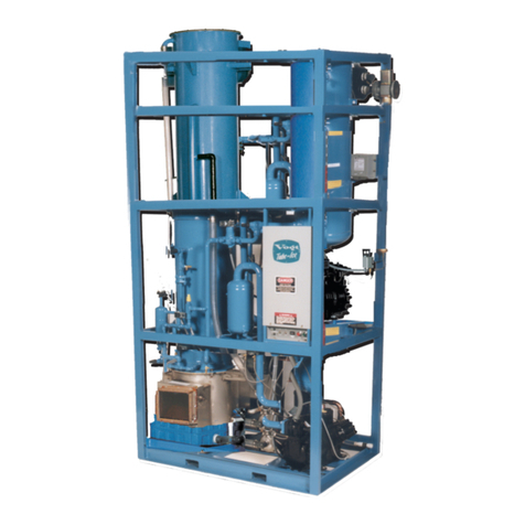
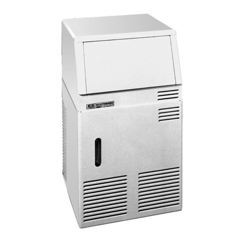
Vogt TUBE-ICE 05TA User manual

NOTICE
This manual is the property of the owner of this particular Tube-Ice®
machine.
Model #____________________ Serial #____________________.
It is to be left on the premises with this machine at all times. After start-up,
it should be stored in a safe place where it can be readily available when
needed for future reference in maintaining troubleshooting or servicing.
Failure to comply with this notice will result in unnecessary inconvenience
and possible additional expenses.
This manual is intended as an informational tool for the installation,
operation, maintenance, troubleshooting, and servicing of this equipment.
If an existing situation calls for additional information not found herein, we
suggest that you contact your distributor first. If further assistance or
information is needed, please feel free to contact the factory at 502-635-
3000 or FAX at 502-635-3024.
IMPORTANT: To activate the machine warranty, the Product Registration
Form MUST be completed and returned to the factory promptly after the
official start-up. Product Registration Form is located in the Owners Packet
or can be found online at www.vogtice.com/registration.htm.
Please return to: VOGT ICE, LLC
Suite #19
1000 W. Ormsby Ave.
Louisville, KY 40210

VOGT ICE
, LLC, located in
Louisville, Kentucky since 1880.
Sales - (800) 853-8648
Service - (502) 635-3000
Parts - Your Local Distributor
Call your local distributor first for all of your parts and service needs.
Since 1880, Manufacturers of Quality
Tube-Ice
®
Machines

05TA Service Manual
TABLE OF CONTENTS
i
TABLE OF CONTENTS
Vogt
®
TUBE-ICE
®
MACHINES
Model 05TA (P118F)
Page No.
1. INTRODUCTION
A Brief History Of Our Company..................................................................................................................................1-1
Vogt Energy-Savings Tube-Ice® Machines ..................................................................................................................1-1
Preview .....................................................................................................................................................................1-1
Important Safety Notice.................................................................................................................................................1-2
Special Precautions To Be Observed When Charging Refrigeration Systems...............................................................1-2
Safety Symbols and What They Mean...........................................................................................................................1-3
Assembly Drawing Model 05TA (P118F) Air-Cooled, FIGURES 1-1, 1-2, & 1-3.......................................................1-4, 1-5, 1-6
Assembly Drawing Model 05TA (P118F) Water Cooled, FIGURES 1-4, 1-5, & 1-6 ..................................................1-7, 1-8, 1-9
2. RECEIPT OF YOUR TUBE-ICE MACHINE
Inspection .....................................................................................................................................................................2-1
Safety Valves .................................................................................................................................................................2-1
Machine Room ..............................................................................................................................................................2-1
Storage (prior to installation and start-up).....................................................................................................................2-2
Vogt Model Nomenclature, FIGURE 2-1......................................................................................................................2-2
3. INSTALLING YOUR TUBE-ICE MACHINE
Water Supply and Drain Sizes, TABLE 3-1 ..................................................................................................................3-1
Cooling Tower...............................................................................................................................................................3-2
Space Diagram (Air-Cooled Machine), FIGURE 3-2A.................................................................................................3-3
Space Diagram (Water Cooled Machine), FIGURE 3-2B .............................................................................................3-4
Control Panel Power Connections FIGURE 3-3 ...........................................................................................................3-5
Electrical Specifications, TABLE 3-2 ...........................................................................................................................3-5
Phase Check, Voltage and Current unbalance ...............................................................................................................3-6
Rotation Check ..............................................................................................................................................................3-6
Air-Cooled Condenser Installation Instructions ............................................................................................................3-7
Pounds of R-22/404A to Add Vs. Liquid Line Length, TABLE 3-3.............................................................................3-8
Air-Cooled Condenser Data, TABLE 3-4......................................................................................................................3-9
Condenser Dimensions, FIGURE 3-4............................................................................................................................3-10
Condenser Field Piping (Cold Weather Valve Kit), FIGURE 3-5.................................................................................3-10
Condenser Equivalent Line Size Worksheet..................................................................................................................3-11
Equivalent Feet Due To Friction, TABLE 3-5...............................................................................................................3-11
Minimum Traps For Discharge Lines, FIGURE 3-6 .....................................................................................................3-11
Wiring For DD-311 and DD-361 Condensers (3 phase motors), FIGURE 3-7.............................................................3-12
Rota-lock Connector Torque Ratings, TABLE 3-6 .......................................................................................................3-12
Ice Bin Thermostat Sensor.............................................................................................................................................3-13
Typical Bin Sensor Mounting, FIGURE 3-8 .................................................................................................................3-13

05TA Service Manual
TABLE OF CONTENTS
ii
Page No.
3. INSTALLING YOUR TUBE-ICE MACHINE (Cont.)
Programming Electronic Bin Thermostat FIGURE 3-9.................................................................................................3-14
Installation Review: A Checklist ..................................................................................................................................3-15
4. HOW YOUR TUBE-ICE MACHINE WORKS
Principle of Operation ...................................................................................................................................................4-1
Freeze Period .................................................................................................................................................................4-2
Harvest Period ...............................................................................................................................................................4-2
Piping Nomenclature TABLE 4-1 .................................................................................................................................4-2
Water Cooled Piping Schematic, FIGURE 4-1..............................................................................................................4-3
Air-Cooled Piping Schematic, FIGURE 4-2..................................................................................................................4-4
5. START-UP AND OPERATION
Refrigeration System Review ........................................................................................................................................5-1
Refrigerant Charge.........................................................................................................................................................5-1
Start-up Checklist ..........................................................................................................................................................5-2
Control Panel Switch Layout, FIGURE 5-1 ..................................................................................................................5-3
Start-up Procedure ........................................................................................................................................................5-3
Adding Refrigerant ........................................................................................................................................................5-4
Operating Tips ...............................................................................................................................................................5-5
6. ELECTRICAL CONTROLS
Control Panel, FIGURE 6-1…………………………………………………………………………………………….6-1
Control Panel Components (Standard), FIGURE 6-2....................................................................................................6-2
Control Panel Door w/Power monitor option (Standard), FIGURE 6-2A .....................................................................6-3
Control Panel Components (CE & Australian approval), FIGURE 6-2B......................................................................6-4
Control Panel Components and Part Numbers, TABLE 6-1 .........................................................................................6-5
Description of Control Panel Component Function, TABLE 6-2..................................................................................6-6
Electrical Schematic All Voltages 50-60 Hz. All Voltages, FIGURE 6-3 .....................................................................6-7
Copeland Compressor Overload Module Wiring Diagram, FIGURE 6-4 .....................................................................6-8
7. MAINTENANCE
Ice-Making Section........................................................................................................................................................7-1
Cleaning Procedure........................................................................................................................................................7-1
Sanitizing Procedure......................................................................................................................................................7-2
Water Distributors .........................................................................................................................................................7-3
Number of Water Distributors Per Tube Size, TABLE 7-1 ...........................................................................................7-3
Water Tank ....................................................................................................................................................................7-3
Water Cooled Condensers .............................................................................................................................................7-3
Water Cooled Condensers, Checking Operation ...........................................................................................................7-3
Water Cooled Condensers, Draining .............................................................................................................................7-4
Water Cooled Condensers, Chemical Cleaning .............................................................................................................7-5
Water Cooled Condensers, Mechanical Cleaning..........................................................................................................7-5,7-6
Lubrication ....................................................................................................................................................................7-6

05TA Service Manual
TABLE OF CONTENTS
iii
Page No.
7. MAINTENANCE (Cont.)
Lubrication, Compressor, FIGURE 7-1
…………………………………………………………………………
7-6
Compressor Recommended Lubricants, TABLE 7-2
……………………………………………………………
7-6
Compressor Oil Capacity Table7-3 ………………………………………………………………………………… 7-7
Cutter Gear Reducer Lubrication, FIGURE 7-2 ........................................................................................................... 7-7
Preventive Maintenance...................................................................................................................................................7-8, 7-
9
Preventive Maintenance Program....................................................................................................................................7-10
8. TROUBLESHOOTING
List Of Symptoms............................................................................................................................................................8-1
Machine Won’t Run ........................................................................................................................................................8-2, 8-3
Freeze-Up Due To Extended Freezing Period .................................................................................................................8-4
Freeze-Up Due To Ice Failing To Discharge...................................................................................................................8-5
Low Ice Capacity.............................................................................................................................................................8-6
Low Compressor Oil Level..............................................................................................................................................8-7
Poor Ice Quality...............................................................................................................................................................8-8
High Head Pressure (Water Cooled)................................................................................................................................8-9
High Head Pressure (Air-Cooled)....................................................................................................................................8-10
9. SERVICE OPERATIONS
Adjustable Blowdown (For Clearer Ice) FIGURE 9-1 ....................................................................................................9-1
Automatic Blowdown (Harvest Cycle) ............................................................................................................................9-1
Float Valve (Make-Up Water) .........................................................................................................................................9-1
Float Switch.....................................................................................................................................................................9-2
Hansen Refrigerant Float Switch, FIGURE 9-2...............................................................................................................9-2
Hand Expansion Valve ....................................................................................................................................................9-3
Freezer Pressure Switch...................................................................................................................................................9-3
Freezer Pressure Switch (Allen-Bradley), FIGURE 9-3 ..................................................................................................9-3
High/Low Pressure Switch ..............................................................................................................................................9-4
High/Low Pressure Switch, FIGURE 9-4........................................................................................................................9-4
Head Pressure ..................................................................................................................................................................9-4
Water Cooled Units .........................................................................................................................................................9-4
Air-Cooled Units .............................................................................................................................................................9-5
Water Regulating Valve, FIGURE 9-5A .........................................................................................................................9-5
Condenser Fan Switch, FIGURE 9-5B............................................................................................................................9-5
Solenoid Valves...............................................................................................................................................................9-5
“X” Solenoid Valve, FIGURE 9-6A & 9-6B...................................................................................................................9-6
“D” Solenoid Valve, FIGURE 9-7A................................................................................................................................9-7
“A” Solenoid Valve, FIGURE 9-7B................................................................................................................................9-7
Oil Separator....................................................................................................................................................................9-8
Oil Separator, FIGURE 9-8 .............................................................................................................................................9-8
Compressor Crankcase Heater .........................................................................................................................................9-8
Copeland Discus Compressor, FIGURE 9-9 ...................................................................................................................9-8
Compressor Motor Protection, Electronic .......................................................................................................................9-9

05TA Service Manual
TABLE OF CONTENTS
iv
Page No
9. SERVICE OPERATIONS (Cont.)
High Potential Testing ....................................................................................................................................................9-10
Field Troubleshooting......................................................................................................................................................9-11
Sentronic Oil Pressure Safety Control FIGURE 9-11......................................................................................................9-12
Sentronic Oil Pressure Sensor .........................................................................................................................................9-13
Sentronic Oil Pressure Module........................................................................................................................................9-13
CoreSense Protection Module .........................................................................................................................................9-13
CoreSense Protection Faults and wiring FIGURE 9-11A................................................................................................9-14
Circulating Water Pump Motor .......................................................................................................................................9-15
Water Pump, FIGURE 9-12.............................................................................................................................................9-15
Cutter Gear Reducer ........................................................................................................................................................9-15
Gear Reducer, FIGURE 9-13...........................................................................................................................................9-15
Thawing Timer, FIGURE 9-14A .....................................................................................................................................9-16
Thawing Timer Wiring, FIGURE 9-14B .........................................................................................................................9-16
Condenser Cleaning.........................................................................................................................................................9-17
Air-Cooled Condenser.....................................................................................................................................................9-17
Pump Down .....................................................................................................................................................................9-17
Removal Of Refrigerant From Machine ..........................................................................................................................9-18
Refrigerant Leaks.............................................................................................................................................................9-18
Non-Condensable Gases..................................................................................................................................................9-18
Compressor Motor Burnout.............................................................................................................................................9-19
Capacity Control Valve (Compressor Unloader).............................................................................................................9-20
Copeland Compressor Unloader Valve, FIGURE 9-15...................................................................................................9-20
Loaded Operation (Freeze Period)...................................................................................................................................9-20
Unloaded Operation (During Thaw Only).......................................................................................................................9-20
Cutter Motor ....................................................................................................................................................................9-21
Cutter Gear Reducer ........................................................................................................................................................9-21
Water Tank Removal .......................................................................................................................................................9-22
Cutter & Bearing Removal/Installation ...........................................................................................................................9-22
Cutter Assembly, FIGURE 9-16......................................................................................................................................9-23
Cutter Drive Parts, FIGURE 9-17....................................................................................................................................9-23
Cutter Parts (Cylinder Ice), FIGURE 9-18A....................................................................................................................9-24
Cutter Parts (Crushed Ice), FIGURE 9-18B ....................................................................................................................9-25
Crushed Ice Production ...................................................................................................................................................9-25
Defrost Pressure Switch (DPS), FIGURE 9-19 ...............................................................................................................9-26
Pressure Relief Valves.....................................................................................................................................................9-26
Technical Service Bulletin: Water Conditioning .............................................................................................................9-27
10. OPTIONS AND ACCESSORIES
Power Monitor, FIGURE 10-1 ....................................................................................................................................... 10-2
Power Monitor, Parameters ............................................................................................................................................ 10-3
Programmable Logic Controller (PLC) .......................................................................................................................... 10-4
PLC Input/output Table .................................................................................................................................................. 10-6

05TA Service Manual
TABLE OF CONTENTS
v
Page No
10. OPTIONS AND ACCESSORIES
PLC Wiring ................................................................................................................................................................... 10-7
Operator Interface Information (HMI).............................................................................................................................10-8
HMI Screens....................................................................................................................................................................10-9
11. TABLES AND CHARTS
05TA Specifications, 208-230V-3Ph-60Hz, TABLE 11-1..............................................................................................11-2
05TA Specifications, 380V-3Ph-50Hz, TABLE 11-2 .....................................................................................................11-3
05TA Capacity Ratings, TABLE 11-3.............................................................................................................................11-4
Condenser Water Usage, TABLE 11-4............................................................................................................................11-5
Make-up Water Usage (gpm), TABLE 11-5....................................................................................................................11-5
Normal Operating Vitals, TABLE 11-6...........................................................................................................................11-5
Recommended Spare Parts List ......................................................................................................................................11-6
Temperature - Pressure Chart for Common Refrigerants, TABLE 11-7..........................................................................11-7
Conversion Factors: English to Metric, TABLE 11-8 .....................................................................................................11-8
Constants, TABLE 11-9 ..................................................................................................................................................11-8
12. INDEX

05TA Service Manual
TABLE OF CONTENTS
vi

05TA Service Manual
INTRODUCTION
7/19/13
1-1
1. Introduction
VOGT ICE
, LLC
A Brief History Of Our Company. Henry Vogt Machine Co. was founded as a small machine
shop in Louisville, Kentucky in 1880. In 1938, Vogt built the first Tube-Ice
®
machine and
revolutionized the ice-making industry. Our first “sized-ice” machine quickly replaced the old can-
ice plants, which required much hard labor and large amounts of floor space for freezing, cutting,
and crushing ice by hand.
Today , VOGT ICE
, LLC carries on the tradition as one of the world’s leading producers of ice-
making equipment.
Vogt Energy-Saving Tube-Ice Machines Are Cost Effective. Today, Vogt Tube-Ice
®
machines
enjoy a well-earned reputation as the most energy efficient, dependable ice-making equipment in the
world.
Using as little as one-half to one-third the energy required by competitors’ icemakers, Tube-Ice
®
machines produce the same amount of ice--in restaurants, sports arenas, packing plants, and
wholesale operations around the globe--at great savings.
In addition, Tube-Ice
®
machines are renowned for their long life, giving many customers more than
35 years of dependable service. Ask someone who owns one.
Preview. All the skill in engineering and fabrication that we have learned in over a century of
experience, is reflected in the 05TA model Tube-Ice
®
machines. Since Vogt introduced Tube-Ice
®
machines in 1938, the process of making Tube-Ice
®
ice has been widely recognized as the most
economical means of production. The machine’s economic and reliable operations have been proven
over and over again, in a network of varied types of installations throughout the world.
Furnished with your machine is the “Certificate Of Test”--the report of operating data that is a record
of the unit’s satisfactory operation on our factory test floor. It is evidence of our desire to deliver to
you “the finest ice-making unit ever made.”
This manual is designed to assist you in the installation, start-up, and maintenance of your unit.
Your Tube-Ice
®
machine will give you a lifetime of service when you install it, maintain it, and
service it properly.
Please read your manual carefully before attempting installation, operation, or servicing of this
professionally designed piece of equipment.
If you have additional questions, please call your distributor. Also, feel free to phone the factory
direct at (502) 635-3000 OR 1-800-853-8648.

05TA Service Manual
INTRODUCTION
7/19/13
1-2
Important Safety Notice. This information is intended for use by individuals possessing adequate
backgrounds of electrical, refrigeration and mechanical experience. Any attempt to repair major
equipment may result in personal injury and property damage. The manufacturer or seller cannot be
responsible for the interpretation of this information, nor can it assume any liability in connection
with its use.
Special Precautions To Be Observed When Charging Refrigeration Systems. Only technically
qualified persons, experienced and knowledgeable in the handling of refrigerant and operation of
refrigeration systems, should perform the operations described in this manual. All local, federal, and
EPA regulations must be strictly adhered to when handling refrigerants.
If a refrigeration system is being charged from refrigerant cylinders, disconnect each cylinder when
empty or when the system is fully charged. A gage should be installed in the charging line to
indicate refrigerant cylinder pressure. The cylinder may be considered empty of liquid R-22/404A
refrigerant when the gauge pressure is 25 pounds or less, and there is no frost on the cylinder. Close
the refrigerant charging valve and cylinder valve before disconnecting the cylinder. Loosen the
union in the refrigerant charging line--carefully to avoid unnecessary and illegal release of refrigerant
into the atmosphere.
! CAUTION !
Immediately close system charging valve at commencement of defrost or thawing cycle if
refrigerant cylinder is connected. Never leave a refrigerant cylinder connected to system
except during charging operation. Failure to observe either of these precautions can result in
transferring refrigerant from the system to the refrigerant cylinder, over-filling it, and
possibly causing the cylinder to rupture because of pressure from expansion of the liquid
refrigerant.
! CAUTION !
Always store cylinders containing refrigerant in a cool place. They should never be exposed to
temperatures higher than 125°F and should be stored in a manner to prevent abnormal mechanical
shocks.
Also, transferring refrigerant from a refrigeration system into a cylinder can be very dangerous and is
not recommended.
! CAUTION !
It is not recommended that refrigerant be transferred from a refrigeration system directly into
a cylinder. If such a transfer is made, the refrigerant cylinder must be an approved, CLEAN
cylinder--free of any contaminants or foreign materials--and must be connected to an
approved recovery mechanism with a safety shutoff sensor to assure contents do not exceed net
weight specified by cylinder manufacturer or any applicable code requirements.
! CAUTION !

05TA Service Manual
INTRODUCTION
7/19/13
1-3
Safety Symbols & What They Mean. Prior to installation or operation of the Tube-Ice
®
machine,
please read this manual. Are you familiar with the installation, start-up, and operation of a Tube-Ice
®
machine? Before you operate, adjust or service this machine, you should read this manual,
understand the operation of this machine, and be aware of possible dangers.
These Safety Symbols will alert you
when special care is needed.
Please heed.
! DANGER !
Indicates an immediate hazard and that special precautions
are necessary to avoid severe personal injury or death.
! DANGER !
! WARNING !
Indicates a strong possibility of a hazard and that an
unsafe practice could result in severe personal injury.
! WARNING !
! CAUTION !
Means hazards or unsafe practices could result
in personal injury and/or product and/or property damage.
! CAUTION !

05TA Service Manual
INTRODUCTION
7/19/13
1-4
` FIGURE 1-1
Assembly (Air-Cooled)
Front View
(5R) CUTTER GEAR REDUCER
1/2" MPT MAKE UP WATER
CONNECTION
(55) DISCHARGE LINE
STOP VALVE
(22A) FLOAT SWITCH STOP VALVE
(22) FLOAT SWITCH
(94) OIL PRESSURE SWITCH
(5M) CUTTER MOTOR
SOLENOID VALVE "A"
FLARE
(17) HAND EXPANSION VALVE
(6) CIRCULATING
WATER PUMP
(28) CHARGING VALVE 1/4"
(12) MAKE-UP WATER
ICE DISCHARGE
(20) LIQUID LINE
FLOAT VALVE
(43) STRAINER
(1PG) LOW PRESSURE GAGE
(2PG) HIGH PRESSURE GAGE
(59) RECEIVER ACCESS VALVE
(30) RECEIVER GAGE
GLASS
(18) THAW GAS SOLENOID
VALVE (VALVE "D")
VALVE
(50) RECEIVER SAFETY VALVE
(31) RECEIVER GAGE GLASS
STOP VALVE
(51) FREEZER SAFETY VALVE
(32) CONDENSER SERVICE
(101) CHECK VALVE
(44) RECEIVER DRAIN VALVE

05TA Service Manual
INTRODUCTION
7/19/13
1-5
FIGURE 1-2
Assembly (Air-Cooled)
Rear View
CHAMBER
(8) WATER DISTRIBUTING
(6A) WATER PUMP
CHECK VALVE
(16) THAWING CHAMBER
(88) SUCTION ACCUMULATOR
VALVE
(7) WATER TANK
(2) FREEZER
(46) LIQUID LINE
FILTER DRIER
(35) COMPRESSOR
DISCHARGE SERVICE
(34) COMPRESSOR SUCTION
SERVICE VALVE
(13) HEAT EXCHANGER
(25) WATER TANK DRAIN
CONNECTION 1" FPT
(3) COMPRESSOR
(91) LIQUID RETURN
STOP VALVE
(15R) RECEIVER

05TA Service Manual
INTRODUCTION
7/19/13
1-6
FIGURE 1-3
Assembly (Air-Cooled)
Right
Side View
("X" VALVE)
(14) OIL SEPARATOR
(58) LIQUID OUTLET STOP
VALVE ("KING" VALVE)
(55) DISCHARGE LINE
STOP VALVE
(4PS) DUAL HIGH/LOW
PRESSURE SWITCH
(41A) CONDENSER PRESSURE
CONTROL SWITCH
(18S) DEFROST PRESSURE
SWITCH
SOLENOID VALVE
(53) COLD WEATHER
DISCHARGE MUFFLER
(48) COMPRESSOR

05TA Service Manual
INTRODUCTION
7/19/13
1-7
FIGURE 1-4
Assembly (Water Cooled)
Front View
(17) HAND EXPANSION VALVE
FLARE
FLOAT VALVE
SOLENOID VALVE "A"
(41) CONDENSER WATER
REGULATOR
(22) FLOAT SWITCH
(43) STRAINER
(20) LIQUID LINE
(5M) CUTTER MOTOR
(12) MAKE-UP WATER
(28) CHARGING VALVE 1/4"
(1PG) LOW PRESSURE GAGE
(2PG) HIGH PRESSURE GAGE
(59) RECEIVER ACCESS VALVE
1/4" FLARE
(30) RECEIVER GAGE
GLASS
(18) THAW GAS SOLENOID
VALVE "D"
(90) THAWING GAS STOP
VALVE
(15) CONDENSER
(50) RECEIVER SAFETY VALVE
5/8" FLARE
(52) CONDENSER SAFETY VALVE
(1) CONTROL PANEL
(94) OIL PRESSURE SWITCH
(44) RECEIVER DRAIN VALVE
(31) RECEIVER GAGE GLASS
STOP VALVE
(24) CONDENSER WATER
(23) CONDENSER WATER INLET
OUTLET
(5R) CUTTER GEAR REDUCER
(22A) FLOAT SWITCH STOP VALVE
1/2" MPT MAKE UP WATER
CONNECTION

05TA Service Manual
INTRODUCTION
7/19/13
1-8
FIGURE 1-5
Assembly (Water Cooled)
Rear View
(51) FREEZER SAFETY VALVE
(8) WATER DISTRIBUTOR
CHAMBER
STOP VALVE
(55) DISCHARGE LINE
WATER PUMP
(6) CIRCULATING
(16) THAWING CHAMBER
(6A) WATER PUMP
CHECK VALVE
(88) SUCTION ACCUMULATOR/
HEAT EXCHANGER
(7) WATER TANK
(2) FREEZER
(46) LIQUID LINE
FILTER DRIER
(35) COMPRESSOR DISCHARGE
SERVICE VALVE
(34) COMPRESSOR SUCTION
SERVICE VALVE
(13) HEAT EXCHANGER
(25) WATER TANK DRAIN
CONNECTION 1" FPT
(3) COMPRESSOR
(91) LIQUID RETURN
STOP VALVE
(15R) RECEIVER

05TA Service Manual
INTRODUCTION
7/19/13
1-9
FIGURE 1-6
Assembly (Water Cooled)
Right Side View
DISCHARGE MUFFLER
(48) COMPRESSOR
(15) CONDENSER
(14) OIL SEPARATOR
(58) LIQUID OUTLET STOP
VALVE ("KING" VALVE)
PRESSURE SWITCH
(4PS) DUAL HIGH/LOW
SWITCH
(18S) DEFROST PRESSURE

05TA Service Manual
INTRODUCTION
7/19/13
1-10
Other manuals for TUBE-ICE 05TA
1
This manual suits for next models
1
Table of contents
Other Vogt Ice Maker manuals

Vogt
Vogt TUBE-ICE P-34AXL User manual

Vogt
Vogt TUBE-ICE P-24ALOF User manual

Vogt
Vogt HE S Series Installation manual

Vogt
Vogt TUBE-ICE 05TA User manual

Vogt
Vogt P18AL TUBE-ICE User manual

Vogt
Vogt VT40 User manual

Vogt
Vogt P-34AL-15 User manual

Vogt
Vogt HEC-10 User manual

Vogt
Vogt TUBE-ICE 10TA User manual

Vogt
Vogt TUBE-ICE P34FXL User manual