Vogtlin M-Flow Series User manual

Vögtlin Instruments
GmbH
–
flow technology
Langenhagstrasse 1 | 4147 Aesch (Switzerland)
Phone. 41 (0)61 756 63 00 | Fax +41 (0)61 756 63 01
Instruction Manual
Precision Control Valves M-Flow

Instruction Manual Version Page
M-Flow mflow_D5_0 © Vögtlin Instruments GmbH 02
Version: mflow_D5_0
Current information on our products can be found on the Internet at www.voegtlin.com© 2019
Vögtlin GmbH, Switzerland
Original Instruction Manual
Precision Control Valves M-Flow

Instruction Manual Version Page
M-Flow mflow_D5_0 © Vögtlin Instruments GmbH 03
Index
Index 3
Product description and intended use 4
Intended use 4
Safety Instructions 4
Copyright and privacy policy 4
Disclaimer 5
Warranty 5
Predictable risks 7
Corrosive Gases 7
High-precision control valve type marking 8
Technical data M-Flow 8
Wetted Materials M-Flow 8
M-Flow types 10
Installation and commissioning 10
Installation instructions 10
Note when operating with flammable or toxic gases 10
Instructions for commissioning 10
CV-values high-precision control valves M-Flow 11
Disassembly and maintenance 12
Important notes on disassembly from the system 12
Maintenance 12
Soiling 12
Cleaning 12
Return 12
Disassembly Digiturn M-Flow 13
Appendix 14
Contamination declaration 15

Instruction Manual Version Page
M-Flow mflow_D5_0 © Vögtlin Instruments GmbH 04
High-precision control valve
We are glad that you have decided to use our high-precision control valves. Our instruments will
provide you with high-quality long-lived products.
This manual contains important information for commissioning and/or designing equipment. Please
contact your distribution partner if anything is not clear.
We are committed to the continual improvement of our products and documentation. Your
experience from everyday use can assist us with this. We welcome your comments and criticisms.
Product description and intended use
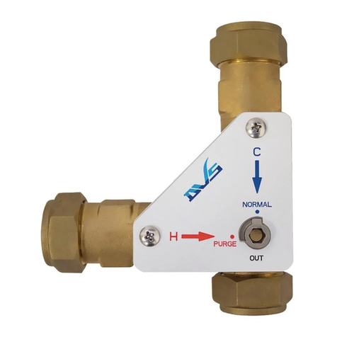
The precision control valves are purely mechanical and are used to adjust flow and shut off. Some
applications:
- Setting a leakage during pressure control
- Throttling of the flow rate so that a pressure can be regulated slowly
- Inerting in various processes (displacement of oxygen)
- Oxygen input from fish transport container
Intended use
The operator of the system is responsible for the safe operation of the control valves and takes
precautions to avoid consequential damage in the event of a device defect (leakage). In particular,
only materials which are resistant to the gas used may be used for corrosive gases. (See also
notes on "corrosive gases" and " predictable risks).
Safety Instructions
Improper handling can cause the control valve to leak and gas to enter the environment. In the
event of a leakage, the escaping gas can cause damage to the environment and/or personal injury.
Copyright and privacy policy
We have prepared this operating manual with all due care. However, no responsibility is taken for
the correctness, completeness and topicality of the contents.
This document is subject to copyright. Processing, in particular translation into another language,
as well as distribution require the written consent of the manufacturer.
Data transmission via computer networks may be subject to security gaps. A complete protection
of the data against access by third parties is therefore not possible.

Instruction Manual Version Page
M-Flow mflow_D5_0 © Vögtlin Instruments GmbH 05
Disclaimer
The manufacturer is not liable for any damages whatsoever resulting from the use of this product.
The operator is responsible for the correct installation, commissioning and safe operation of this
product.
These products are warranted according to the current product information and the manufacturer's
terms of sale and delivery.
The manufacturer reserves the right to change the contents of the documents, including this
disclaimer, in any way and without notice. The manufacturer is not liable in any way for any
consequences of such changes.
Warranty
The warranty for the products described in this manual is limited to defects in material and
workmanship. Warranty does in no case exceed product replacement free of charge. All claims are
null and void in the case of improper use:
Use outside operating limits
Damage caused by pressure surges (see also " predictable risks)
Corrosion damage caused by operation with gases which were not intended for this
purpose at the origin, as well as by external influences.
Mechanical damage in general

Instruction Manual Version Page
M-Flow mflow_D5_0 © Vögtlin Instruments GmbH 06
Vögtlin Instruments GmbH

Instruction Manual Version Page
M-Flow mflow_D5_0 © Vögtlin Instruments GmbH 07
Predictable risks
Before commissioning the system, the operator must take appropriate precautions to ensure that
the environment and/or persons are protected in the event of a fault.
Leakage of the control valves can result in the following risks:
- Escaping gas can be suffocating, toxic and/or corrosive. Please read the safety data sheet
of the used gas or gas mixture from the respective gas supplier carefully beforehand.
- When flammable gases escape, an explosive gas mixture can form in the environment.
- In the case of aggressive media, leakage can lead to corrosion damage to the device
and/or in the immediate vicinity.
The following causes can lead to gas leakage:
- The valve becomes leaky because it is operated with a gas which was not intended for this
purpose at the origin. As a result, gas may leak if the seals are not resistant to this gas.
- The process connections are not tight due to improper installation. A leak test must be
carried out before commissioning.
The possible causes of gas leakage are not conclusive and may have other causes as well.
Corrosive Gases
The operator is solely responsible for the safe operation of the system and takes precautions to
protect the environment and/or persons in the event of leaks.
The valve may only be operated with the gases for which the valve has been designed and
specified.
Sealing materials for corrosive gases
The manufacturer shall propose the sealing material suitable for the specified gas. The data on
resistance are taken from the literature of our suppliers. Therefore, we cannot guarantee the
specified sealing material.
Operation with ozone gas (O3)
The durability of the sealing material depends strongly on the operating conditions.
In ozone applications, concentration, humidity and temperature have a decisive influence on the
resistance of the sealing material used.
Vögtlin Instruments only supplies a device for O3 if the customer/plant operator himself determines
the sealing material.
The same applies to unknown media and gas mixtures.

Instruction Manual Version Page
M-Flow mflow_D5_0 © Vögtlin Instruments GmbH 08
High-precision control valve type marking
For the M-Flow the type label is attached to the valve cartridge housing.
An arrow on the body of the valve indicates the flow direction.
Example:
Key:
NS 2.5: Specification of valve size NS 1.0 to NS 6.5
L: Closing direction for valve (L = left / R = right)
V: Sealing material (V = FKM / E = EPDM / P = FFKM
Custom designed instruments can have additional details such as leakage rate.
Technical data M-Flow
Betreff M-Flow 25 M-Flow 35
Straight valve
Valve insert / Cartridge
Valve rotations 15 15
Valve size NS 1.0 bis 3.0 NS 4 und 6.5
Leak rate <1x10⁻⁵ mbar l/s He <1x10⁻⁵ mbar l/s He
Pressure resistance 20 bar 20 bar
Minimum temperature 0°C 0°C
Maximum temperature 100°C 100°C
Connecting threads G ¼“ G ½“
Wetted Materials M-Flow
Component Materials
Valve Body Anodized Aluminium, optional Stainless Steel 1.4305 (AISI 303)
Valve insert/cartdrige Nickel-plated brass, optional Stainless Steel 1.4305 (AISI 303)
Connections Stainless Steel 1.4305 (AISI 303)
Seals FKM, optional EPDM or FFKM

Instruction Manual Version Page
M-Flow mflow_D5_0 © Vögtlin Instruments GmbH 09
Version M-Flow
Standard knob
Valve cartridge (valve core)
Standard knob with locking ring
Hexagon socket with lock nut (instead of rotary knob)
Straight valve G ¼"
Hexagon socket 3 mm
SW 13 mm
Can be ordered as spare part

Instruction Manual Version Page
M-Flow mflow_D5_0 © Vögtlin Instruments GmbH 10
M-Flow types
Digiturn with display (100 graduation, clockwise closing)
Installation and commissioning
Installation instructions
The control valve may only be installed and commissioned by qualified personnel.
The pipeline must be free of particles before installing the control valve. Please flush them
before installing the valve in the pipeline.
The process connections must not be sealed with sealing tape or liquid sealer. Residues might
enter the instrument and lead to defects
(See also paragraph Recommended connections)
Before commissioning, make sure that the connections are sealed
Note when operating with flammable or toxic gases
When closed the control valve closes thigtly with an O-ring. For flammable and/or toxic gases,
we recommend the use of an additional shut-off device.
Instructions for commissioning
The operating limits must not be exceeded
(See section Technical Information)
Connect the control valve to the flow meter or other control element
Open the media supply
Slowly open the control valve and set the required set value
(See also section Operating principle of the variable area flow meter)

Instruction Manual Version Page
M-Flow mflow_D5_0 © Vögtlin Instruments GmbH 11
CV-values high-precision control valves M-Flow
CV-values valves NS1.0 to NS6.5
Opening point:
To ensure that the control valve closes tightly, an O-ring is used to seal the valve seat. A flow
therefore only occurs after about 2 turns.
CV-value 1 = 1 m3/h water at Δp of 1bar
0.0000001
0.000001
0.00001
0.0001
0.001
0.01
0.1
1
0 2 4 6 8 10 12 14 16
cv-values
spindle turns
NS-1.0
NS-1.5
NS-2.0
NS-2.5
NS-3.0
NS-4.0
NS-6.5

Instruction Manual Version Page
M-Flow mflow_D5_0 © Vögtlin Instruments GmbH 12
Disassembly and maintenance
Important notes on disassembly from the system
Please close the gas supply, flush the pipes and then close the shut-off valves. Make sure
that the line is depressurized and that no dangerous gas can enter the environment. You
can then start disassembling the control valve. Only use suitable tools for this purpose. The
removal and installation of the valves may only be carried out by qualified personnel.
Maintenance
When used correctly, variable area flow meters from Vögtlin Instruments GmbH do not require any
maintenance.
Soiling
The following symptoms indicate soiling:
The set value can no longer be reached – the control valve is probably soiled
The measuring value rises although the actual flow rate has not been changed – measuring
cylinder is soiled
Cleaning
Depending on the type of soiling, the measuring instrument can be rinsed with isopropyl alcohol
(IPA). The measuring cylinder can be mechanically cleaned with a brush at the most.
If soiled, we recommend that you return the measuring instrument to your distribution
partner.
Return
When returning, please use the original packaging if possible or suitable alternative packaging. We
do not accept responsibility for damage in transit. Please inform us of the reason for return: this
enables us to process your request quickly.
Note
If the instrument has been in contact with corrosive or toxic media it is imperative to clean it
properly before return. Please always complete the contamination declaration form. This is
provided in the appendix to this manual.
Instruments which we receive without a contamination declaration form will unfortunately have to
be returned to the sender.

Instruction Manual Version Page
M-Flow mflow_D5_0 © Vögtlin Instruments GmbH 13
Disassembly Digiturn M-Flow
Close the rotary knob or valve until the scale shows 00.00
Open the cover ring 633-1104 and remove from the rotary knob
Unscrew the M5x5 setscrew. The back part of the knob can be pulled off
(hexagon socket, key size 2.5 mm)
Unscrew the two setscrews 512-8202 on the adapter sleeve 518-1575. The adapter sleeve can
be pulled off (hexagon socket, key size 1.5 mm)
Loosen the two setscrews on the adjusting ring 518-1563. The ring can be pulled off
(hexagon socket, key size 2 mm)
The rotary knob is now completely dismounted from the valve
Recommended connections
We recommend that you only use process connections that seal with an O-ring or a suitable
sealing ring. For example:
Compression fitting for metal pipes
Push-in connectors for
PUR hose
Hose nozzles for soft hose

Instruction Manual Version Page
M-Flow mflow_D5_0 © Vögtlin Instruments GmbH 14
Appendix
Dimensions high-precision control valves M-Flow

Instruction Manual Version Page
M-Flow mflow_D5_0 © Vögtlin Instruments GmbH 15
Contamination declaration
With return of devices, please fill out the following statement completely, especially the reason
for the return, the type of residue and cleaning in the case of soiling, as well as indication of
hazards.
Device:
Type code:
Serial number:
Reason for return:
Type of contamination
Device came in contact with:
Cleaned by us with:
Can you provide further
information on the
contamination?
inert (no danger)
corrosive
caustic
must not come in contact with moisture
oxidizing
other hazards:
For the protection of our employees and for general safety during transport, proper cleaning and
the use of appropriate packaging are mandatory.
Legal declaration
We hereby confirm the correctness and completeness of the above information:
Company:
Adress:
Phone:
Contact person:
Date:
Signature:

Instruction Manual Version Page
M-Flow mflow_D5_0 © Vögtlin Instruments GmbH 16
Change log
Date Version Replaces Author Note
01.03.2010 vflow_D4_3 vflow_D4_2 MHU Page 21 / New Article Code
17.01.2011 vflow_D4_4 vflow_D4_3 MHU Page 9, 10: Material of limit stop added
07.05.2012 vflow_D4_5 vflow_D4_4 LEU Page 18 / Sealing Material
02.04.2014 vflow_D4_6 vflow_D4_5 LEU Page 31 / Drawing
22.04.2014 vflow_D4_7 vflow_D4_6 LEU Page 11 / Drawing
27.06.2019 mflow_D4_8 Vflow_D4_7 JER General adaptions according to „Retrofit”
08.07.2019 mflow_D4_9 mflow_D4_8 MHU Layout
15.10.2019 mflow_D5_0 mflow_D4_9 FLU Layout, general adaptions
This manual suits for next models
2
Table of contents
Other Vogtlin Control Unit manuals
