Vogue 330286 Mounting instructions

VOGUE Ceiling Rangehood 1100mm
To prevent the risk of accidents or damage to the appliance, it is essential
to read these instructions before it is installed and used for the first time
330286
INSTALLATION
INSTRUCTIONS
USER GUIDE

CONTENTS
SAFETY INSTRUCTIONS 3
INSTALLATION 5
START USING YOUR RANGEHOOD 8
REMOTE CONTROL 9
TROUBLESHOOTING 10
MAINTENANCE AND CLEANING 11
ENVIRONMENT PROTECTION 12

3
SAFETY INSTRUCTIONS
This manual explains the proper installation and use of your cooker hood, please read it carefully
before using even if you are familiar with the product. The manual should be kept in a safe place
for future reference.
Never to do:
• Donottrytousethecookerhoodwithoutthegreaseltersoriftheltersareexcessivelygreasy!
• Do not install above a cooker with a high level grill.
• Donotleavefryingpansunattendedduringusebecauseoverheatedfatsoroilsmightcatchre.
• NeverleavenakedamesundertheRangehood.
• If the cooker hood is damaged, do not attempt to use.
• Donotambéunderthecookerhood.
• CAUTION: Accessible parts may become hot when used with cooking appliances.
• The minimum distance between the supporting surface for the cooking vessels on the hob and
the lowest part of the cooker hood. (When the cooker hood is located above a gas appliance, this
distance shall be at least 65 cm)
• Theairmustnotbedischargedintoauethatisusedforexhaustingfumesfromappliances
burning gas or other fuels.
Always to do:
• Important!Alwaysswitchotheelectricitysupplyatthemainsduringinstallationand
maintenance such as light bulb replacement.
• The cooker hood must be installed in accordance with the installation instructions and all
measurements followed.
• Allinstallationworkmustbecarriedoutbyacompetentpersonorqualiedelectrician.
• Please dispose of the packing material carefully. Children are vulnerable to it.
• Pay attention to the sharp edges inside the cooker hood especially during installation and
cleaning.
• When the cooker hood is located above a gas appliance,the minimum distance between the
supporting surface for the cooking vessels on the hob and the lowest part of the cooker
hood that distance must be:
Gas cookers: 75 cm
Electric cookers: 65 cm
Coal or oil cookers: 75 cm
• Makesuretheductinghasnobendssharperthan90degreesasthiswillreducetheeciencyof
the cooker hood.
• Warning:Failuretoinstallthescrewsorxingdeviceinaccordancewiththeseinstructions
may result in electrical hazards

4
Always to do:
• Warning: Before obtaining access to terminals, all supply circuits must be disconnected.
• Always put lids on pots and pans when cooking on a gas cooker.
• When in extraction mode, air in the room is being removed by the cooker hood. Please
make sure that proper ventilation measures are being observed. The cooker hood
removes odours from room but not steam.
• Cooker hood is for domestic use only
• If the supply cord is damaged, it must be replaced by the manufacturer, its service agent or
similarlyqualiedpersonsinordertoavoidahazard.
• This appliance can be used by children aged from 8 years and above and persons with
reduced physical, sensory or mental capabilities or lack of experience and knowledge if they
have been given supervision or instruction concerning use of the appliance in a safe way and
understand the hazards involved. Children shall not play with the appliance. Cleaning and user
maintenance shall not be made by children without supervision.
• Warning: Before obtaining access to terminals, all supply circuits must be disconnected.
• Caution: The appliance and its accessible parts can become hot during operation. Be careful to
avoid touching the heating elements. Children younger than 8 years old should stay away unless
they are under permanent supervision.
• There shall be adequate ventilation of the room when the cooker hood is used at the same time
as appliances burning gas or other fuels.
• Thereisareriskifcleaningisnotcarriedoutinaccordancewiththeinstructions
• Regulationsconcerningthedischargeofairhavetobefullled.
• Clean your appliance periodically by following the method given in the chapter MAINTENANCE.
• Forsafetyreason,pleaseuseonlythesamesizeofxingormountingscrewwhichare
recommended in this instruction manual.
• Regardingthedetailsaboutthemethodandfrequencyofcleaning,pleaserefertomaintenance
and cleaning section in the instruction manual.
• Cleaning and user maintenance shall not be made by children without supervision.
• When the cooker hood and appliances supplied with energy other than electricity are
simultaneously in operation, the negative pressure in the room must not exceed 4 Pa
(4 x 10⁻⁵ bar).
• WARNING:Dangerofre:donotstoreitemsonthecookingsurfaces.
• A steam cleaner is not to be used.
• NEVERtrytoextinguisharewithwater,butswitchotheapplianceandthencoveramee.g.
withalidorareblanket

5
INSTALLATION (VENT OUTSIDE)
MOUNTING OF THE V-FLAP
IfthecookerhooddoesnothaveanassembledV-ap1,youshouldmountthehalf-partstoits
body.TheimagesonlyshowanexampleofhowtomounttheV-ap,theoutletmaybevarious
accordingtodierentmodelsandconguration.
TomounttheV-ap1youshould:
• Mount two half-parts 2 into the body 6
• A pin 3 should be top oriented;
• The axis 4 should be inserted in the holes 5 on body;
•Repeatalltheoperationsforthe2ndhalf-part
INSTALLATION
1.Beforeinstallation,turntheunitoandunplugitfromtheoutlet.
2. The cooker hood should not be placed at a distance of no more than 150cm from the cooking
surfaceforthebestperformance.RefertoPic1.
3. The ceiling must can bear at least 120KGs weight, and the thickness of the ceiling must be
≥30MM.
4. According to the size shown on Pic 2, drill 14pcs
φ8mmholesontheceilingoncetheinstallationheightis
determined,14pcs explode screws(or 14pcs of ST6*40mm
bigatscrews+14pcswallplugs)willbeusedtoxthe
two hanging board on the ceiling.( See Pic. 3)
5. Calculate the length of the angle iron(refer to Pic 4/5),then 32pcs of M4*10 screws and M4 nut
with gasket will be used to connect the angle iron into the adjustable angle iron bracket. (Make sure
the overlap length of angle iron cannot less than 36mm)

6
6. As Pic 9 shown, choose the direction of the outlet 1 / 2 / 3 / 4
a.RefertoPic7,openthedecorativeplateinorder,andtakeoutthelter.
b.RefertoPic8,unscrewandtakeawaythe4pcsST4*8mmscrewsthatonthepaneldecorative
strip.
c. Unscrew the 8pcs machine silk from the bottom of the cabinet housing and rotate it by
90°/180°/270°tochoosethedirectionoftheoutlet,thenscrewthe8pcsmachinesilktoxthe
housing well;
d.Installthepaneldecorativestripandlterwellapplytothereverseorderofa/bsteps
above,meanwhile, install the expansion pipe to the outlet(refer to pic 10).
7. As Pic 11 shown, connect the 4 adjustable angle iron bracket with the housing by 8pcs
M4*12mm machine silk screw, next refer to Pic 12/13, lift up the housing, use 8pcs M4*12mm
machinesilkscrewandM4nutwithgaskettoxthehousingontothe2hangingboard,meanwhile,
pulltheexpansionpipeoutside.(Note:Theexpansionpipemustbexedonthehousingrmly.)

7
8. After installing the housing to the hanging board, use cross screwdriver or straight screwdriver
to adjust the screw of the angle iron bracket, direct the housing level position and height till it is
suitable. Adjust method: Adjust rang of the angle iron
Bracket is 0-25mm, clockwise twist the screw of the 4 angle iron bracket, slightly move the
housing upwards; meanwhile, anticlockwise twist the screw of the angle iron bracket, slightly move
the housing downwards. Use the cross screwdriver to screw the safety screw tightly after the level
positionandheightissuitable.(RefertoPic14)
HINTS FOR EXHAUST DUCT INSTALLATION
The following rules must be strictly followed to obtain optimal air extraction:
• Keep expansion pipe short and straight.
• Do not reduce the size or restrict expansion pipe.
• When using expansion pipe always install the pipe pulled taut to minimize pressure loss.
• Failure to observe these basic instructions will reduce the performance and increase noise levels
of the cooker hood.
•Anyinstallationworkmustbecarriedoutbyaqualiedelectricianorcompetentperson.
• Do not connect the ducting system of the hood to any existing ventilation system which is being
used for any other appliance ,such as warmer tube, gas tube , hot wind tube.
• The angle of the bend of the expansion pipe should not be less than 120º; you must direct the
pipe horizontally, or, alternatively, the pipe should go up from the initial point and should be led to
an outer wall.
• After the installation ,make sure that the cooker hood is level to avoid grease collection at on end.
• Ensure the expansion pipe selected for installation complies with relevant standards and is
reretardant.
WARNING • For safety reason, please use only the same size of
xingormountingscrewwhicharerecommendedin
this instruction manual.
• Failuretoinstallthescrewsorxingdevicein
accordance with these instructions may result in
electrical hazards.

8
START USING YOUR RANGEHOOD
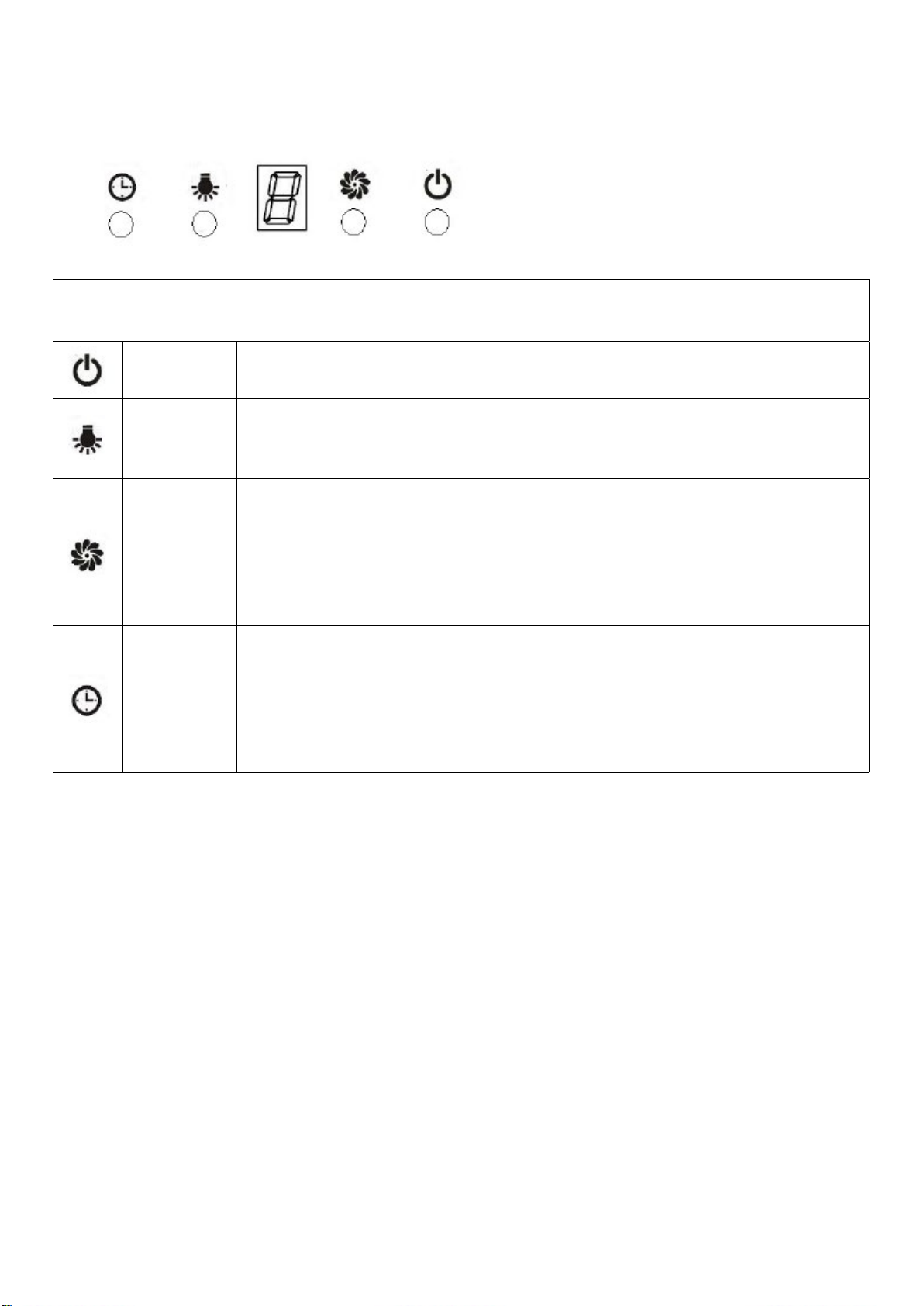
Electronic button with LED display & remote
After connecting to power, the control panel will be lighted and the buzzer will sound once.
Theoutputisoandthehoodenterintostandbymode.
On/O Switchestheventilationonando.
Light Switchesthelightonando.PleasenotetheLampisnotundercontrolof
theon/obutton.
Ventilation
Speed
The motor has the low speed, mid. speed and high speed.
When the hood is working with low speed, LED display will show 1.
Press the button, then the hood will transfer to the mid speed for working;
the LED will show 2 , press the speed button again , the hood will transfer
to the high speed for working immediately. And so on…
Timer
This is a 9 minute timer. When the hood is working, press this button to set
a time for motor operation. Press the button ,LED display will be shown
9.8.7.6until0,WhenLCDshows0,thehoodwillbeoautomaticallyand
the lamp will extinguish. If keep pressing “Timer” button, the hood will go in
or go out “Timer” function.
Connecting the remote control
• A New remote control has to establish a new connection to the cooker hood when used for
rsttime.Oneremotecontrolcouldpossiblycontrolseveralcookerhoodatthesametime.
Connection process between remote control and Rangehood
• Within 15S after the cooker hood connects to the power supply, long press for 5 seconds, the
indicatorslightbeginashingfromonebuttontoanother,thecookerhoodisinconnection
mode,pressanybuttononremotecontroltoconrmtheconnection.Theconnectionprocess
nishedandtheremotecontrolcanbeusedforspeedselection,lightingandtimersetting.
• If you want to connect again, you will need to clear the code that has been set up previously.
• Toclearthecode,pressfor5seconds,theindicatorslightbeginashingfromonebuttontoa
other, the cooker is in connection mode. Then, press again for 5 seconds, the previous
connection code is cleared.
• When the previous code has been cleared, the cooker hood back to standby mode, press
for5seconds,theindicatelightashingfromonebuttontoanother,thecookerhoodisin
connectionmode,then,pressanybuttononremotecontroltoconrmtheconnection.

9
REMOTE CONTROL
1. Lightingpressbuttononce,thelightison,pressagain,thelightiso.
Thelightingbuttonitiscontrolledseparatelyandwillnotaectanyotherfunctions.
2. Turning on/ Increasing motor speed key the motor has low, mid, high totally 3 levels.
2.1 Press one time,the motor will work at low speed (Turning on).
2.2 When the hood works at low speed, touch again,the motor changes to mid speed.
2.3 Base on the middle speed condition, touch again, the motor is running in the
high speed.
2.4 Base on the high speed condition, touch again, the hood still works at high speed.
3. Turningo/Decreasingmotorspeedkey
3.1 press the button and the motor begins shift to a lower speed and the LCD screen
displaythespeedlevel.Repeatingpressthebutton,itkeepondecreasingthemotorspeed
tillthecookerhoodturningo.
4. Low speed, mid speed and high speed cannot work at the same time. When hood is on high
speed, press the speed decrease, it will turn to a lower speed; when it is in low speed, press
the speed increase, it will turn to a higher speed.
5. Timer
Pressthebuttontosetupthetimeron/ofunction.

10
TROUBLESHOOTING
FAULT POSSIBLE CAUSE SOLUTION
Light on, but motor does not
work
Fanswitchturnedo Select a fan switch position.
Fan switch failed Contact service center.
Motor failed Contact service center.
Light does not work, motor
does not work
House fuses blown Reset/Replacefuses.
Power cord loose or discon-
nected
Retcordtopoweroutlet.
Switch power outlet on.
Oil leakage
One way valve and the outlet
are not tightly sealed
Take down the one way valve
and seal with sealant.
Leakage from the connection
of chimney and cover Take chimney down and seal.
Lights not working Broken/Faulty globes Replaceglobesasperthis
Insucientsuction
The distance between the
cooker hood and the gas top
is too far
Retthecookerhoodtothe
correct distance.
The Cooker hood inclines Thexingscrewnottight
enough
Tighten the hanging screw
and make it horizontal.
NOTE: Any electrical repairs to this appliance must conform to your local, state and
federal laws. Please contact the service centre if in any doubt before undertaking any of
the above. Always disconnect the unit from the power source when opening the unit.

11
MAINTENANCE AND CLEANING
CAUTION:
• Before maintenance or cleaning is carried out, the cooker hood should be disconnected from the
mainpowersupply.Ensurethatthecookerhoodisswitchedoatthewallsocketandtheplug
removed.
• External surfaces are susceptible to scratches and abrasions, so please follow the cleaning
instructions to ensure the best possible result is achieved without damage.
GENERAL
Cleaning and maintenance should be carried out with the appliance cold especially when cleaning.
Avoid leaving alkaline or acid substances (lemon juice, vinegar etc.) On the surfaces.
STAINLESS STEEL
The stainless steel must be cleaned regularly (e.g. weekly) to ensure long life expectancy. Dry with
acleansoftcloth.Aspecializedstainlesssteelcleaninguidmaybeused.
NOTE:
Ensure that wiping is done along with the grain of the stainless steel to prevent any unsightly criss-
cross scratching patterns from appearing.
CONTROL PANEL SURFACE
The inlay control panel can be cleaned using warm soapy water. Ensure the cloth is clean and well
wrung before cleaning. Use a dry soft cloth to remove any excess moisture left after cleaning.
IMPORTANT
Using neutral detergents and avoid using harsh cleaning chemicals, strong household detergents
orproductscontainingabrasives,asthiswillaecttheapplianceappearanceandpotentiallyre-
move any printing of artwork on the control panel and will void manufactures warrantee.
GREASE MESH FILTERS
Themeshlterscanbecleanedbyhand.Soakthemforabout3minuteinwaterwitha
grease-loosening detergent then brush it gently with a soft brush. Please do not apply too much
pressure, avoid to damage it . (Leave to dry naturally out of direct sun light)
Filters should be washed separately to crockery and kitchen utensils. It is advisable not to use
rinse aid.

12
ENVIRONMENTAL PROTECTION:
This product is marked with the symbol on the selective sorting of waste electronic
equipment. This means that this product must not be disposed of with household
waste but must be supported by a system of selective collection in accordance with
Directive 2012/19/EU. It will then be recycled or dismantled to minimize impacts
on the environment, electrical and electronic products are potentially dangerous for
the environment and human health due to the presence of hazardous substances.
For more information, please contact your local or regional authorities.
NOTE:
The following shows how to reduce total environmental impact (e.g. energy use) of the cooking
process).
(1) Installthecookerhoodinaproperplacewherethereisecientventilation.
(2) Clean the cooker hood regularly so as not to block the airway.
(3) Remembertoswitchothecookerhoodlightaftercooking.
(4) Remembertoswitchothecookerhoodaftercooking.
INFORMATION FOR DISMANTLING
Do not dismantle the appliance in a way which is not shown in the user manual. The appliance
could not be dismantled by user. At the end of life, the appliance should not be disposed of with
household waste. Check with you Local Authority or retainer for recycling advice.
CARBON FILTER-not supplied
Activatedcarbonltercanbeusedtotrapodors.Normallytheactivatedcarbonltershouldbe
changed at three or six months according to your cooking habit. The installation procedure of
activatedcarbonlterisasbelow.
Inordertoinstalltheactivatedcarbonlter,thealuminiumltershouldbedetachedrst.Firstly
opencarefullythestainlesssteelcover,thenpressthelockofaluminiumlterandremoveit.
NOTE:
Makesurethelterissecurelylocked.
Otherwise, it would loosen and cause dangerous.
Whenactivatedcarbonlterattached,thesuction
power will be lowered.
Table of contents
Other Vogue Ventilation Hood manuals

Vogue
Vogue 330264 Wiring diagram

Vogue
Vogue 330157 Wiring diagram

Vogue
Vogue 330291 Wiring diagram

Vogue
Vogue 330289 Wiring diagram

Vogue
Vogue RH.VG.600T User manual

Vogue
Vogue RH.CANOPY.600.SS User manual

Vogue
Vogue 330267 Wiring diagram

Vogue
Vogue RH.600.WH User manual

Vogue
Vogue 330171 Wiring diagram

Vogue
Vogue 330410 Wiring diagram