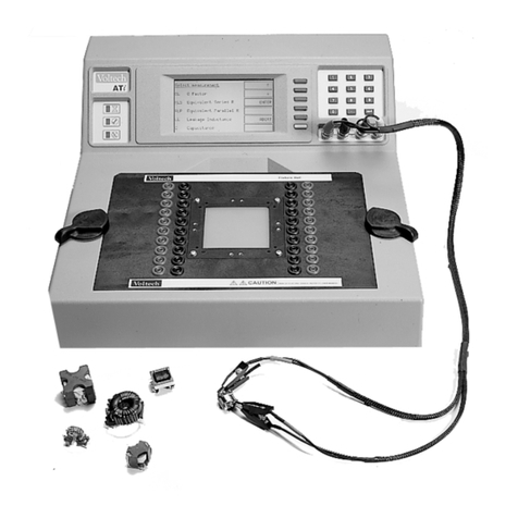
Voltech AT5600 User manual

AT5600 User Manual 98-119 issue 14 Page 1
VOLTECH INSTRUMENTS
AT5600 Wound Component Tester
User Manual

AT5600 User Manual 98-119 issue 14 Page 2
Voltech AT5600 Wound Component Tester
AT5600 User Manual
Thank you for choosing the Voltech AT5600. This wound component tester
should give you many years of reliable use. Should you experience any
difficulty during the set up or use of your Voltech product, please do not
hesitate to contact either your local supplier or one of our main offices.
Voltech Instruments Ltd
66 Innovation Drive
Milton Park
Abingdon
Oxfordshire
OX14 4RQ
UK
Phone +44 1235 861173
Voltech Instruments Inc.
12851 Banyan Creek Drive
Fort Myers
FL 33908
USA
Phone +1 239 437 0494
sales@voltech.com
www.voltech.com
©Voltech Instruments All rights reserved
No part of this publication may be produced, stored in a retrieval system, or transmitted in
any form, or by means, electronic, mechanical photocopying, recording or otherwise
without prior written permission of Voltech
Issue 14 –18 FEB 2019 / Firmware 1.001.026

AT5600 User Manual 98-119 issue 14 Page 3
Table of Contents
1. Introduction ................................................................................................... 11
1.1. AT5600 New Features............................................................................................................11
1.2. How to use this manual ..........................................................................................................12
1.2.1. How to Use this Manual –English...................................................................................12
1.2.2. Mode d'utilisation de ce manuel –Français ....................................................................12
1.2.3. Verwendung dieses Handbuchs –Deutsch ....................................................................13
1.2.4. Cómo Usar Este Manual –Español ................................................................................13
1.2.5. Come usare questo manuale –Italiano ..........................................................................14
1.2.6. Zo gebruikt u deze handleiding –Nederlands.................................................................14
1.2.7. Sådan bruger du denne manual –Dansk .......................................................................15
1.2.8. Så här använder du bruksanvisningen –Svenska..........................................................15
1.2.9. Tämän oppaan käyttöohjeet –Suomi .............................................................................16
1.2.10. Použití této příručky – Ceština.....................................................................................16
1.2.11. Hogy kell használni ezt a kézikönyvet –Magyar .........................................................17
1.2.12. Jak korzystać z niniejszej instrukcji – Polski................................................................17
1.2.13. Kılavuzun Kullanımı - Türkçe.......................................................................................18
1.3. General Safety Instructions ....................................................................................................19
1.3.1. General safety Instructions - English...............................................................................19
1.3.2. Consignes générales de sécurité –Français ..................................................................20
1.3.3. Allgemeine Sicherheitshinweise –Deutsch ....................................................................21
1.3.4. Instrucciones Generales de Seguridad –Español..........................................................22
1.3.5. Istruzioni generali di sicurezza –Italiano ........................................................................23
1.3.6. Algemene veiligheidsinstructies –Nederlands................................................................24
1.3.7. Generel sikkerhedsvejledning –Dansk...........................................................................25
1.3.8. Allmänna säkerhetsanvisningar –Svenska ....................................................................26
1.3.9. Yleiset turvallisuusohjeet –Suomi...................................................................................27
1.3.10. Obecné bezpečnostní pokyny – Ceština .....................................................................28
1.3.11. Általános biztonsági utasítások –Magyar ...................................................................29
1.3.12. Ogólne instrukcje bezpieczeństwa – Polski.................................................................30
1.3.13. Genel Güvenlik Talimatları - Türkçe ............................................................................31
1.4. Package Contents ..................................................................................................................32
2. System Overview........................................................................................... 33
2.1. What is the AT5600? ..............................................................................................................33
2.2. What is the AT5600 used for? ................................................................................................34
2.3. AT5600 Features Summary ...................................................................................................34
2.4. Front Panel Description ..........................................................................................................35
2.5. Rear Panel Description...........................................................................................................37
2.6. Air Circulation .........................................................................................................................41
2.7. Tilt Feet...................................................................................................................................42
2.8. Lifting Points ...........................................................................................................................42
2.9. A Typical Installation...............................................................................................................43
2.9.1. Server PC –results and test program management.......................................................43
2.9.2. Editor PC –test program development ...........................................................................43
2.9.3. Test Fixture......................................................................................................................44
2.9.4. Light Curtain (or another safety device) ..........................................................................44
3. Using the AT5600 .......................................................................................... 45

AT5600 User Manual 98-119 issue 14 Page 4
3.1. Usage Overview .....................................................................................................................45
3.2. Test Fixtures ...........................................................................................................................46
3.3. Creating Test Programs - AT Editor .......................................................................................47
3.4. Utilizing Editor Test Programs ................................................................................................49
3.4.1. Storing programs on the Server ......................................................................................49
3.5. Results Printing.......................................................................................................................51
3.5.1. Report Format .................................................................................................................51
3.6. Recommended Configuration.................................................................................................53
3.7. Operating the AT5600 in Production Test ..............................................................................54
3.7.1. Manual Use .....................................................................................................................54
3.7.2. Robotic Operation ...........................................................................................................54
4. AT5600 Functional Description.................................................................... 55
4.1. Behind the Front Panel...........................................................................................................55
4.1.1. Test Nodes ......................................................................................................................55
4.1.2. Relay Switching Matrix ....................................................................................................56
4.1.3. Processors.......................................................................................................................56
4.1.4. Test Sources ...................................................................................................................56
4.1.5. Measurement Circuits .....................................................................................................57
4.1.6. Touch Screen & Buttons .................................................................................................58
4.1.7. Interfaces.........................................................................................................................58
4.2. How Does the AT5600 Tester Run a Test? ...........................................................................59
5. Getting Started .............................................................................................. 61
5.1. Installing the AT5600..............................................................................................................61
5.2. Installing the Windows Software.............................................................................................61
5.3. Install the Server Software .....................................................................................................61
5.4. Quick Start Tutorial.................................................................................................................62
5.4.1. Creating a Simple Schematic ..........................................................................................62
5.4.2. Creating the Test Program..............................................................................................64
5.4.3. Running the Program from the Editor .............................................................................71
5.4.4. Transferring the Program to the Server ..........................................................................72
5.5. USB Printer Setup ..................................................................................................................77
6. Safety Systems.............................................................................................. 81
6.1. Introduction .............................................................................................................................81
6.2. Recommended Safety Systems .............................................................................................82
6.2.1. Description of the OMRON Light Curtain System ...........................................................82
6.2.2. Description of the Banner Light Curtain system..............................................................82
6.2.3. Constructing your own Safety System ............................................................................83
6.3. Safety Notices.........................................................................................................................84
6.4. A Typical Installation of a Safety System ...............................................................................84
6.5. The AT5600 safety system user interface..............................................................................86
6.6. Constructing Safe Fixtures .....................................................................................................87
6.7. DC1000 DC Bias Current Source...........................................................................................87
6.8. AC Interface Fixture................................................................................................................87
7. Tests and Test Conditions............................................................................ 89
7.1. Available Tests .......................................................................................................................89
7.1.1. LOW VOLTAGE Tests ....................................................................................................90
7.1.2. HIGH VOLTAGE Tests....................................................................................................92
7.1.3. DC1000 Tests..................................................................................................................93
7.1.4. AC INTERFACE Tests ....................................................................................................93
7.2. Self-Resonant Frequency.......................................................................................................94
7.3. Explanation of Integration.......................................................................................................95
7.4. CTY - Continuity .....................................................................................................................97
7.5. R - Winding Resistance ..........................................................................................................98
7.6. RLS or RLP - Equivalent Series or Parallel Resistance .......................................................100
7.7. LS or LP - Inductance (Series or Parallel Circuit).................................................................101

AT5600 User Manual 98-119 issue 14 Page 5
7.8. LSB or LPB-Inductance with Bias Current (Series or Parallel Circuit) .................................104
7.9. QL - Quality Factor ...............................................................................................................105
7.10. D –Dissipation Factor or Tan ...........................................................................................106
7.11. LL - Leakage Inductance ..................................................................................................107
7.12. C - Interwinding Capacitance............................................................................................109
7.13. TR - Turns Ratio................................................................................................................112
7.14. TRL - Turns Ratio by Inductance ......................................................................................117
7.15. Z, ZB –Impedance, Impedance with Bias ........................................................................119
7.16. R2 –DC Resistance Match...............................................................................................120
7.17. L2 –Inductance Match......................................................................................................121
7.18. C2 –Capacitance Match...................................................................................................124
7.19. GBAL –General Longitudinal Balance .............................................................................126
7.20. LBAL –Longitudinal Balance............................................................................................129
7.21. ILOS –Insertion Loss .......................................................................................................130
7.22. RESP –Frequency Response ..........................................................................................131
7.23. RLOS –Return Loss.........................................................................................................132
7.24. ANGL –Impedance Phase Angle.....................................................................................133
7.25. PHAS –Interwinding Phase Test......................................................................................134
7.26. OUT –Output to User Port ...............................................................................................135
7.27. IR - Insulation Resistance .................................................................................................136
7.28. HPDC - DC HI-POT (EHT)................................................................................................137
7.29. HPAC - AC HI-POT (EHT) ................................................................................................138
7.30. SURG - Surge Stress Test................................................................................................140
7.31. WATT - Wattage ...............................................................................................................144
7.32. WATX - Wattage (External Source) ..................................................................................145
7.33. STRW –Stress Watts .......................................................................................................147
7.34. STRX –Stress Watts (External Source)...........................................................................148
7.35. MAGI - Magnetizing Current .............................................................................................150
7.36. MAGX - Magnetizing Current (External Source)...............................................................152
7.37. VOC - Open Circuit Voltage..............................................................................................154
7.38. VOCX - O/C Voltage (External Source)............................................................................156
7.39. LVOC –Low Voltage Open Circuit ...................................................................................158
7.40. ILK –Leakage Current Test..............................................................................................160
7.41. LSBX –Inductance with External Bias (Series Circuit).....................................................161
7.42. LPBX –Inductance with External Bias (Parallel Circuit)...................................................162
7.43. ZBX - Impedance with External Bias ................................................................................163
7.44. ACRT - AC HI-POT Ramp ................................................................................................164
7.45. DCRT - DC HI-POT Ramp................................................................................................165
7.46. ACVB - AC Voltage Break Down ......................................................................................166
7.47. DCVB - DC Voltage Break Down......................................................................................167
8. Front Panel Operation................................................................................. 169
8.1. Introduction ...........................................................................................................................169
8.1.1. The Touch Screen Display ............................................................................................169
8.1.2. RUN and STOP buttons ................................................................................................170
8.1.3. User Input ......................................................................................................................170
8.1.4. Splash Screen ...............................................................................................................171
8.1.5. Power On.......................................................................................................................171
8.1.6. PART LIST ....................................................................................................................172
Entering a Part Number............................................................................................................173
Serial Number ..........................................................................................................................175
Batch ........................................................................................................................................176
Operator ...................................................................................................................................177
Compensation ..........................................................................................................................178
Run Screen ..............................................................................................................................182
Results .....................................................................................................................................183
8.1.7. SELF-TEST ...................................................................................................................184
8.1.8. SET UP..........................................................................................................................186
8.1.9. SOUND..........................................................................................................................187
8.1.10. CLOCK.......................................................................................................................188

AT5600 User Manual 98-119 issue 14 Page 6
8.1.11. SERVER ....................................................................................................................189
8.1.12. NETWORK.................................................................................................................190
8.1.13. UNIT INFO.................................................................................................................191
8.1.14. STATUS BAR ICONS................................................................................................192
8.2. Testing Wound Components ................................................................................................193
8.2.1. A Typical Workflow........................................................................................................193
8.2.2. Traceability ....................................................................................................................194
8.2.3. STOP ON FAIL function ................................................................................................195
8.2.4. Getting the Results........................................................................................................196
9. Troubleshooting.......................................................................................... 199
9.1. Measurement Error Codes ...................................................................................................199
9.1.1. Self-test error codes ......................................................................................................199
9.1.2. Editor Error Codes.........................................................................................................200
9.1.3. Status Code Example....................................................................................................200
9.2. Correcting Errors ..................................................................................................................202
9.2.1. Safety Interlock error .....................................................................................................202
9.2.2. Temperature error .........................................................................................................202
9.2.3. Voltage Present Error....................................................................................................203
10. Specifications.............................................................................................. 205
10.1. Specification Summary .....................................................................................................205
10.2. Accuracy Specifications –Available Tests .......................................................................209
10.2.1. R Test ........................................................................................................................209
10.2.2. LS, LP, RLS, RLP, LL and C Tests............................................................................210
10.2.3. QL and D Tests..........................................................................................................211
10.2.4. TR Test ......................................................................................................................212
10.2.5. TRL Test ....................................................................................................................213
10.2.6. MAGI Test..................................................................................................................214
10.2.7. MAGX Test (External Source) ...................................................................................215
10.2.8. VOC Test ...................................................................................................................216
10.2.9. VOCX Test (External Source)....................................................................................217
10.2.10. LVOC Test .................................................................................................................218
10.2.11. IR Test .......................................................................................................................219
10.2.12. HPDC Test.................................................................................................................220
10.2.13. HPAC Test .................................................................................................................221
10.2.14. LSB AND LPB Tests..................................................................................................222
10.2.15. WATT and STRW Tests ............................................................................................223
10.2.16. WATX and STRX Tests (External Source)................................................................224
10.2.17. SURG Test.................................................................................................................225
10.2.18. L2, C2 and R2 Tests..................................................................................................226
10.2.19. GBAL Test .................................................................................................................227
10.2.20. LBAL and ILOS Tests ................................................................................................228
10.2.21. RESP Test .................................................................................................................229
10.2.22. RLOS Test .................................................................................................................230
10.2.23. Z and ZB Test ............................................................................................................231
10.2.24. ANGL Test .................................................................................................................232
10.2.25. PHAS Test .................................................................................................................233
10.2.26. ILK Test......................................................................................................................234
10.2.27. LSBX and LPBX Tests...............................................................................................235
10.2.28. ZBX Test....................................................................................................................236
10.2.29. ACRT Test .................................................................................................................237
10.2.30. DCRT Test.................................................................................................................238
10.2.31. ACVB Test .................................................................................................................239
10.2.32. DCVB Test .................................................................................................................240
10.3. Interface Specifications.....................................................................................................241
10.3.1. Server Port.................................................................................................................241
10.3.2. Auxiliary Port..............................................................................................................241
10.3.3. Remote Port...............................................................................................................242

AT5600 User Manual 98-119 issue 14 Page 7
10.3.4. Peripheral Interface ...................................................................................................244
10.3.5. Safety Interlock ..........................................................................................................245
10.3.6. User Port....................................................................................................................246
10.3.7. Ethernet Port..............................................................................................................248
10.3.8. Front and Rear USB ‘A’ Ports....................................................................................248
10.3.9. USB ‘B’ Port ...............................................................................................................248
10.4. Environmental Conditions .................................................................................................249
10.5. Mechanical ........................................................................................................................250
10.6. EMC Compliance ..............................................................................................................251
10.6.1. Declaration of Conformity ..........................................................................................251
11. Maintenance................................................................................................. 253
11.1. Air Filters ...........................................................................................................................253
11.1.1. Removing the right-hand side panel..........................................................................253
11.1.2. Removing the air filters ..............................................................................................254
11.2. Test Probes.......................................................................................................................254
11.3. Power Cords .....................................................................................................................254
11.4. Cleaning ............................................................................................................................254
12. Warranty and Service.................................................................................. 255
12.1. Warranty Information ........................................................................................................255
12.1.1. Post-sale Warranty Agreement..................................................................................255
12.2. Service and Calibration.....................................................................................................256
12.3. Accessories.......................................................................................................................257
13. Test Fixtures................................................................................................ 259
13.1. Introduction .......................................................................................................................259
13.2. The Voltech Fixture System..............................................................................................260
13.2.1. Description of the Fixture System..............................................................................260
13.2.2. Compatible connection types.....................................................................................261
13.3. The Voltech 40 Socket Fixture..........................................................................................261
13.4. Making Fixture Connections –Kelvin Connections ..........................................................262
13.5. Compensation ...................................................................................................................264
13.5.1. Compensation Summary –Available Tests...............................................................265
13.5.2. Equipment Required ..................................................................................................266
13.6. General Notes...................................................................................................................268
13.6.1. Beware of High Voltages ...........................................................................................268
13.6.2. Kelvin Connections ....................................................................................................269
13.6.3. Mechanical Problems ................................................................................................269
13.6.4. Cleaning Test Pins.....................................................................................................269
14. AT Series Editor Software .......................................................................... 271
14.1. Introduction .......................................................................................................................271
14.2. Installing the Editor Software ............................................................................................272
14.2.1. Computer Requirements............................................................................................272
14.2.2. Installing the USB Drivers..........................................................................................272
14.2.3. Installing the main application....................................................................................273
14.3. Starting for the first time....................................................................................................273
14.3.1. Running the software.................................................................................................273
14.3.2. Language Configuration ............................................................................................273
14.3.3. Communications Configuration..................................................................................273
14.4. Schematic Editing .............................................................................................................274
14.4.1. Adding a Transformer Winding ..................................................................................274
14.4.2. Connecting the Winding Terminals to Nodes ............................................................276
14.4.3. Deleting a Winding.....................................................................................................276
14.4.4. Renaming a Terminal ................................................................................................277
14.4.5. Adding a Terminal to an Existing Winding.................................................................277
14.4.6. Deleting a Terminal from an Existing Winding...........................................................278
14.4.7. Adding a Core Connection.........................................................................................278

AT5600 User Manual 98-119 issue 14 Page 8
14.4.8. Deleting a Core Connection.......................................................................................279
14.4.9. Adding a Screen Connection .....................................................................................279
14.4.10. Deleting a Screen Connection ...................................................................................279
14.5. Creating the Program........................................................................................................280
14.5.1. Setting the Program Options .....................................................................................280
Results Printing ........................................................................................................................281
Kelvin Pre-Check......................................................................................................................282
Operator Numbering.................................................................................................................285
Batch Numbering......................................................................................................................285
Serial Numbering......................................................................................................................285
Send Results to Server ............................................................................................................285
Send Retry Results to Server...................................................................................................285
Stop on Fail ..............................................................................................................................286
Date and Time on Reports .......................................................................................................287
Disable test failures due to ALC error ......................................................................................287
AQL (Acceptable Quality Level) ...............................................................................................288
Run audit test every [X] parts tested........................................................................................288
Fixture ID..................................................................................................................................289
External AC Source..................................................................................................................289
Custom Text .............................................................................................................................289
14.5.2. Program Edit..............................................................................................................290
14.5.3. Adding Tests ..............................................................................................................291
14.5.4. Inserting Tests ...........................................................................................................292
14.5.5. Modifying Tests..........................................................................................................294
14.5.6. Deleting Tests ............................................................................................................295
14.5.7. Test Parameters ........................................................................................................296
14.5.8. Test Limits..................................................................................................................297
14.5.9. Using the Measure Button .........................................................................................299
14.5.10. Verifying Your Program .............................................................................................303
14.5.11. Compensation............................................................................................................305
14.5.12. Hints and Tips ............................................................................................................307
14.5.12.1 Schematic.................................................................................................................307
14.5.12.2 Test Order ................................................................................................................307
14.5.12.3 Test Grouping ..........................................................................................................309
14.6. Programming Tests...........................................................................................................311
14.6.1. CTY - Continuity.........................................................................................................312
14.6.2. R - Winding Resistance .............................................................................................313
14.6.3. RLS or RLP - Equivalent Series or Parallel Resistance ...........................................314
14.6.4. LS or LP –Winding Inductance (Series or Parallel Circuit).......................................316
14.6.5. LSB or LPB - Inductance with Bias (Series or Parallel Circuit) .................................318
14.6.6. QL - Quality Factor ....................................................................................................320
14.6.7. D –Dissipation Factor or Tan..................................................................................322
14.6.8. LL - Leakage Inductance ...........................................................................................323
14.6.9. C - Interwinding Capacitance.....................................................................................325
14.6.10. TR - Turns Ratio ........................................................................................................326
14.6.11. TRL - Turns Ratio (by Inductance) ............................................................................330
14.6.12. Z, ZB –Impedance ....................................................................................................332
14.6.13. L2 - Inductance Match ...............................................................................................334
14.6.14. C2 –Capacitance Match ...........................................................................................335
14.6.15. GBAL –General Longitudinal Balance......................................................................337
14.6.16. LBAL –Longitudinal Balance.....................................................................................339
14.6.17. ILOS –Insertion Loss ................................................................................................340
14.6.18. RESP –Frequency Response...................................................................................341
14.6.19. RLOS –Return Loss..................................................................................................342
14.6.20. ANGL –Impedance Phase Angle..............................................................................343
14.6.21. PHAS –Interwinding Phase Test ..............................................................................345
14.6.22. OUT –Output to User Port ........................................................................................347
14.6.23. IR - Insulation Resistance..........................................................................................348
14.6.24. HPDC - DC Hi-Pot (EHT)...........................................................................................349
14.6.25. HPAC - AC Hi-Pot (EHT)...........................................................................................350

AT5600 User Manual 98-119 issue 14 Page 9
14.6.26. SURG - Surge Stress Test ........................................................................................351
14.6.27. WATT - Wattage ........................................................................................................353
14.6.28. WATX –Wattage (External Source)..........................................................................354
14.6.29. STRW –Stress Wattage............................................................................................355
14.6.30. STRX - Stress Watts (External Source) ....................................................................356
14.6.31. MAGI - Magnetizing Current ......................................................................................357
14.6.32. MAGX - Mag. Current (External Source)...................................................................358
14.6.33. VOC - Open Circuit Voltage.......................................................................................359
14.6.34. VOCX –O/C Voltage (External Source)....................................................................361
14.6.35. LVOC –Low Voltage Open Circuit ............................................................................363
14.6.36. ILK –Leakage Current Test.......................................................................................364
14.6.37. LSBX –Inductance with External Bias (Series Circuit) .............................................365
14.6.38. LPBX –Inductance with External Bias (Parallel Circuit) ...........................................367
14.6.39. ZBX - Impedance with External Bias .........................................................................369
14.6.40. ACRT - AC Hi-Pot Ramp ...........................................................................................371
14.6.41. DCRT - DC Hi-Pot Ramp...........................................................................................372
14.6.42. ACVB - AC Voltage Break Down...............................................................................373
14.6.43. DCVB - DC Voltage Break Down...............................................................................374
14.7. Firmware Upgrades ..........................................................................................................375
14.8. Self-Test............................................................................................................................376
14.9. Customize Tester..............................................................................................................378
15. AT Series Server Software ......................................................................... 379
15.1. Introduction .......................................................................................................................379
15.2. Installing the Server Software ...........................................................................................380
15.2.1. Computer Requirements............................................................................................380
15.2.2. Installation Instructions ..............................................................................................380
15.3. Starting for the first time....................................................................................................381
15.3.1. Running the software.................................................................................................381
15.3.2. Initial Configuration ....................................................................................................381
15.4. Setting up the Options ......................................................................................................382
15.4.1. Communications ........................................................................................................382
15.4.2. Directories..................................................................................................................386
15.4.3. Groups .......................................................................................................................387
15.4.4. Password ...................................................................................................................387
15.4.5. Results .......................................................................................................................388
15.4.6. Language ...................................................................................................................388
15.4.7. Storing Test Programs...............................................................................................389
15.4.8. Viewing a Test Program ............................................................................................390
15.4.9. Deleting a Test Program............................................................................................391
15.5. Test Results Handling.......................................................................................................392
15.5.1. Receiving Test Results ..............................................................................................392
15.5.2. Result Display and Analysis ......................................................................................393
15.5.3. On-Line Monitoring ....................................................................................................394
15.5.4. Batch Statistics On-line Analysis ...............................................................................395
15.5.5. On-Line Analysis via a Database...............................................................................397
Introduction...............................................................................................................................397
Setting Up Database Results Storage .....................................................................................397
Database Tables ......................................................................................................................402
Charting and Analysis Using SPC/SQC Software ...................................................................406
15.5.6. On-Line Analysis via OLE..........................................................................................408
15.5.6.1 Transferring Server Results from Microsoft Access Database (.mdb) to Microsoft Excel
2016 (.xlsx)...............................................................................................................................418
15.5.7. Off-line Analysis.........................................................................................................421
16. Manual, Firmware and Software Change Log........................................... 425
16.1. AT5600 User Manual ........................................................................................................426
16.2. AT5600 Firmware..............................................................................................................428
16.3. AT Series Editor Software.................................................................................................436

C H A P T E R 1 - I N T R O D U C T I O N
AT5600 User Manual 98-119 issue 14 Page 11
1.Introduction
An introduction to the AT5600 Wound Component Tester
This user manual details the operation of the Voltech AT5600 Wound Component
Tester. Please study this introductory chapter carefully as it will help to setup the
product quickly and safely. It will also help to get the most from the product by
introducing all its features and capabilities.
1.1. AT5600 New Features
The AT5600 is the next generation of AT Wound Component Testers offered by
Voltech. New features include:
•2 x faster testing greatly increases productivity
•Ethernet Port
oFor networked server communications
oWireless capability
•USB Ports
oFor simple program editing and printing
•Measurements optimized for speed with accuracy
•Fast stabilization of magnetizing current
•Audit Testing (run specified tests every X parts, where X=2 to 99)
•Diagnostic Testing (run specified tests only if any main + audit test fail)
•Load Compensation
Chapter
1

C H A P T E R 1 - I N T R O D U C T I O N
AT5600 User Manual 98-119 issue 14 Page 12
1.2. How to use this manual
1.2.1. How to Use this Manual –English
The following icon key shows the convention used throughout this manual to help
identify key points that should be read and understood.
Important safety information. All safety information must be read and
understood.
Important information that explains a general principal that should be
understood in order to use the product effectively.
If any information is not clear, then please visit the Voltech website for more
information or contact us for assistance.
1.2.2. Mode d'utilisation de ce manuel –Français
L'icône suivante indique la convention utilisée dans l'ensemble de ce manuel afin
d'identifier les points clés qui doivent être lus et assimilés.
Informations importantes relatives à la sécurité.
Toutes les informations relatives à la sécurité doivent être lues et
assimilées.
Les informations importantes donnent l'explication d'un principe
général qui doit être assimilé afin d'utiliser le produit efficacement.
Si des informations ne sont pas claires, veuillez consulter le site Web de Voltech
pour obtenir un complément d'information ou nous contacter pour obtenir de
l'aide.

C H A P T E R 1 - I N T R O D U C T I O N
AT5600 User Manual 98-119 issue 14 Page 13
1.2.3. Verwendung dieses Handbuchs –Deutsch
Die folgende Symbollegende zeigt die in diesem Handbuch verwendeten
Konventionen zur Hervorhebung wichtiger Punkte, die gelesen und verstanden
werden müssen.
Wichtige Sicherheitshinweise.
Alle Sicherheitshinweise müssen gelesen und verstanden werden.
Wichtige Informationen, die ein allgemeines Prinzip erklären, das
verstanden werden muss, damit das Produkt effektiv genutzt werden
kann.
Falls Informationen nicht klar sind, besuchen Sie bitte die Voltech-Website, um
dort weitere Informationen zu erhalten, oder kontaktieren Sie uns, damit wir Ihnen
weiterhelfen können.
1.2.4. Cómo Usar Este Manual –Español
Las siguientes claves de iconos muestran los avisos convenidos para usarlos en
este manual, para poder identificar aspectos importantes que deben ser leídos y
comprendidos.
Información importante de seguridad.
Toda la información de seguridad tiene que ser leída y comprendida.
Información importante que explica un principio general que debe ser
comprendido para usar el producto con eficacia.
Si alguna información no aparece clara le rogamos visitar el sitio web de Voltech
para mayor detalle o contactarnos para solicitar ayuda.

C H A P T E R 1 - I N T R O D U C T I O N
AT5600 User Manual 98-119 issue 14 Page 14
1.2.5. Come usare questo manuale –Italiano
La seguente legenda mostra le icone convenzionali usate in questo manuale per
segnalare i punti chiave che richiedono un’attenta lettura e comprensione.
Informazioni importanti per la sicurezza.
Tutte le informazioni riguardanti la sicurezza devono essere lette e
comprese.
Informazioni importanti che spiegano un principio generale da
comprendere per utilizzare efficacemente il prodotto.
In caso di dubbi in merito a qualunque informazione contenuta nel manuale,
visitare il sito web Voltech per chiarimenti o contattare gli uffici Voltech per
richiedere assistenza.
1.2.6. Zo gebruikt u deze handleiding –Nederlands
De volgende pictogramtoets toont de conventie die in deze handleiding wordt
gebruikt als hulpmiddel bij het identificeren van de belangrijkste punten die
gelezen en begrepen moeten worden.
Belangrijke veiligheidsinformatie.
Alle veiligheidsinformatie moet gelezen en begrepen worden.
Belangrijke informatie die een algemeen principe verklaart dat men
dient te begrijpen om het product effectief te gebruiken.
Ga naar de Voltech-website voor meer informatie als iets in de informatie niet
duidelijk is, of neem contact met ons op voor hulp.

C H A P T E R 1 - I N T R O D U C T I O N
AT5600 User Manual 98-119 issue 14 Page 15
1.2.7. Sådan bruger du denne manual –Dansk
Det følgende ikon viser den konvention, der bruges i denne manual til at hjælpe
med at identificere de vigtigste punkter, der skal læses og forstås.
Vigtige sikkerhedsoplysninger.
Alle sikkerhedsoplysninger skal læses og forstås.
Vigtige oplysninger, der forklarer et generelt princip, der skal forstås
for at kunne bruge produktet effektivt.
Hvis noget er uklart, skal du besøge Voltechs websted for at få flere oplysninger
eller kontakte os for at få hjælp.
1.2.8. Så här använder du bruksanvisningen –
Svenska
Följande ikoner visar hur viktiga punkter som ska läsas och förstås har markerats
i den här bruksanvisningen.
Viktig säkerhetsinformation.
All säkerhetsinformation måste läsas och förstås.
Viktig information som förklarar en allmän princip som måste förstås
för effektiv användning av produkten.
Om någon information är oklar kan du besöka Voltechs webbplats för mer
information eller kontakta oss för att få hjälp.

C H A P T E R 1 - I N T R O D U C T I O N
AT5600 User Manual 98-119 issue 14 Page 16
1.2.9. Tämän oppaan käyttöohjeet –Suomi
Seuraavassa kuvakkeiden selityksessä näkyy tässä oppaassa käytössä oleva
käytäntö, jolla on merkitty keskeiset seikat, jotka on luettava ja sisäistettävä.
Tärkeitä turvallisuustietoja
Kaikki turvallisuustiedot on luettava ja sisäistettävä.
Tärkeitä tietoja, jotka selittävät yleisperiaatteen, joka on sisäistettävä,
jotta tätä tuotetta voidaan käyttää tehokkaasti.
Jos jotkin tiedot eivät ole selkeitä, saat lisätietoja Voltechin verkkosivustolta tai voit
pyytää meiltä neuvoa.
1.2.10. Použití této příručky – Ceština
Následující symboly jsou používány v celé příručce a usnadňují identifikaci
klíčových bodů, které je nutné prostudovat a pochopit.
Důležité bezpečnostní informace.
Všechny bezpečnostní informace je nutné prostudovat a pochopit.
Důležité informace vysvětlující obecné principy, kterým je v zájmu
efektivního použití produktu nutné porozumět.
Pokud některé informace nejsou srozumitelné, navštivte web společnosti Voltech,
kde naleznete další informace a můžete si vyžádat naši pomoc.

C H A P T E R 1 - I N T R O D U C T I O N
AT5600 User Manual 98-119 issue 14 Page 17
1.2.11. Hogy kell használni ezt a kézikönyvet –
Magyar
Az alábbi ikon jelmagyarázat ismerteti az e kézikönyvben végig alkalmazott
egyezményes jelölést azon fő pontok azonosítására, amelyek elolvasása és
megértése nélkülözhetetlen.
Fontos biztonsági információ.
Minden biztonsági információ elolvasása és megértése kötelező.
Fontos információ egy olyan általános elv ismertetésére, amelyet
érteni kell a termék hatékony alkalmazása érdekében.
Ha bármely információ nem világos, kérjük, látogasson el a Voltech weboldalára
további tájékoztatásért vagy forduljon hozzánk segítségért.
1.2.12. Jak korzystać z niniejszej instrukcji – Polski
Poniższa legenda z opisem znaczenia ikon przedstawia konwencję stosowaną w
niniejszej instrukcji w celu ułatwienia określenia kluczowych informacji do
przeczytania i zrozumienia.
Ważne informacje o bezpieczeństwie.
Wszystkie informacje dotyczące bezpieczeństwa należy przeczytać
i zrozumieć.
Ważne informacje wyjaśniające ogólną zasadę, którą należy
zrozumieć w celu właściwego użytkowania produktu.
Jeśli podane informacje są niejasne, wówczas należy uzyskać dodatkowe
informacje ze strony internetowej firmy Voltech lub skontaktować się z nami z
prośbą o pomoc.

C H A P T E R 1 - I N T R O D U C T I O N
AT5600 User Manual 98-119 issue 14 Page 18
1.2.13. Kılavuzun Kullanımı - Türkçe
Bu kullanım kılavuzunun tümünde kullanılmış aşağıdaki simgeler (ikon), mutlaka
okunup anlaşılması gereken temel hususları göstermektedir.
Önemli güvenlik bilgisi.
Bu türden bütün güvenlik bilgileri mutlaka okunmalı ve anlaşılmalıdır.
Ürünün verimli bir şekilde kullanılması için anlaşılması gereken genel
ilkeleri açıklayan önemli bilgiler.
Tam olarak anlayamadığınız şeyleri lütfen Voltech sitesinde ayrıntılı olarak
inceleyiniz ya da yardım almak için bizimle temas kurunuz.

C H A P T E R 1 - I N T R O D U C T I O N
AT5600 User Manual 98-119 issue 14 Page 19
1.3. General Safety Instructions
1.3.1. General safety Instructions - English
Electrical devices can constitute a safety hazard. It is the responsibility of the user
to ensure the compliance of the installation with any local acts or bylaws in force.
Only qualified personnel should install this equipment after reading and
understanding this user manual. These operating instructions should be adhered
to. If in any doubt, please contact your supplier.
DANGER! ELECTRIC SHOCK RISK
WARNING: The AT5600 must be connected to a safety ground (earth). Only
insert the power lead into a socket with a protective ground contact. Ensure that
the power lead is in good condition and free from damage before use.
Replace the fuses only with the same type and rating: 2.0AT 5X20 ANTISURGE.
Refer servicing only to qualified personnel who understand the danger of shock
hazards.
WARNING: The AT5600 can generate voltages that may be LETHAL. The
safety interlock is designed to ensure the safety of operators when used with a
Voltech approved safety system. To ensure operator safety, this interlock must
always be properly connected to a Voltech approved safety system.
This product has been constructed in compliance with the requirements of
EN61010-1, Pollution Degree 2, and Installation Category II: FOR INDOOR USE
ONLY. This ensures the safety of the instrument and the user when normal
precautions are followed.

C H A P T E R 1 - I N T R O D U C T I O N
AT5600 User Manual 98-119 issue 14 Page 20
1.3.2. Consignes générales de sécurité –Français
Les appareils électriques peuvent constituer un danger pour la sécurité.
Il incombe à l'utilisateur de s'assurer de la conformité de l'installation avec les lois
locales ou les arrêtés municipaux en vigueur.
Seul le personnel qualifié doit installer cet équipement, après avoir lu et assimilé
le manuel de l'utilisateur.
Ces consignes d'utilisation doivent être suivies. En cas de doute, veuillez
contacter votre fournisseur
DANGER ! Risque d'électrocution
ATTENTION : L'AT5600 doit être connecté à une prise de terre de sécurité.
Ne brancher le cordon d'alimentation que sur une prise ayant un contact de
protection avec la terre. S'assurer que le cordon d'alimentation est en bon état
et exempt de dommage avant utilisation. Ne remplacer les fusibles que par des
fusibles de mêmes type et calibre : 2.0AT 5X20 TEMPORISÉ. Ne confier la
révision et la réparation de l'appareil qu'à du personnel qualifié qui a une
connaissance des risques d'électrocution.
ATTENTION : L'AT5600 peut générer des tensions susceptibles d'être
MORTELLES.
Le verrouillage réciproque de sécurité est conçu pour assurer la sécurité des
opérateurs lors de son utilisation avec un système de sécurité agréé par Voltech.
Afin d'assurer la sécurité de l'opérateur, ce verrouillage réciproque doit être
toujours connecté à un système de sécurité agréé par Voltech.
Pour toutes précisions, veuillez consulter le chapitre 6 de ce manuel de
l'utilisateur.
La construction du DC1000A est conforme aux exigences de la norme EN61010-
1, Degré de pollution 2, Catégorie d'installation II: POUR UNE UTILISATION
INTÉRIEURE UNIQUEMENT. La sûreté de l'instrument et la sécurité de
l'utilisateur sont ainsi assurées lorsque les précautions habituelles sont prises.
Table of contents
Other Voltech Test Equipment manuals
Popular Test Equipment manuals by other brands

Hantek
Hantek DSO8000E Series user manual

Presys
Presys TA-1200P Technical manual

Teledyne Lecroy
Teledyne Lecroy WaveJet Touch Getting started guide

Amprobe
Amprobe ROBIN KMP7010 user manual

Keysight Technologies
Keysight Technologies N2142A quick start guide

Keithley
Keithley Interactive SourceMeter 2450 Declassification and security instructions