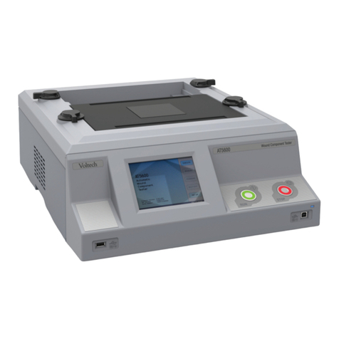
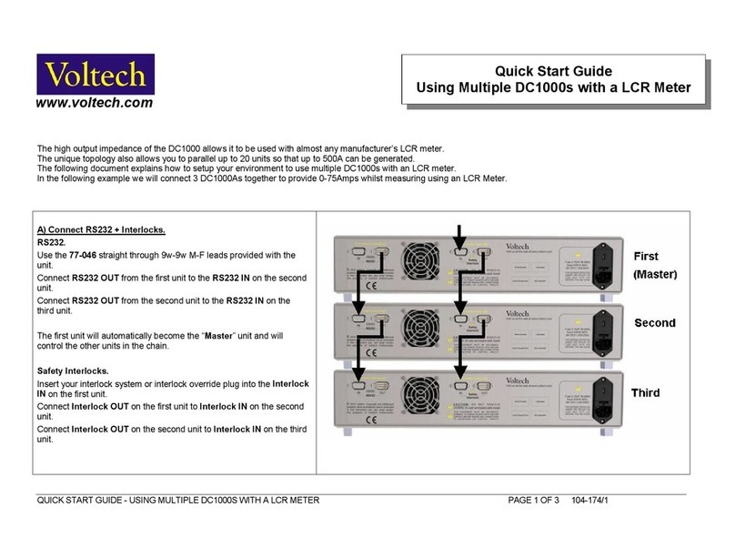
Voltech ATi User manual

VOLTECH ATI USER MANUAL PAGE I
AT
ATAT
ATi
iii
USER MANUAL
V
oltech Instruments Inc.
11637 Kelly Road
Suite 306
Fort Myers FL 33908, U.S.A.
Tel: 239 437 0494
Fax: 239 437 3841
V
oltech Instruments Ltd.
148 6th Street
Harwell International Business Centre
Didcot, Oxon OX11 ORA, U.K.
Tel: +44 (0) 1235 834555
Fax: +44 (0) 1235 835016
www.voltech.com

PAGE II VOLTECH ATI USER MANUAL
Voltech Instruments is committed to a policy of continuous
product development. Hence, product specification and the
information given in this manual are subject to change
without notice.
No part of this publication may be reproduced, stored in a
retrieval system, or transmitted in any form, or by any
means, electronic, mechanical photocopying, recording or
otherwise, without prior written permission of Voltech
Instruments.
Voltech Instruments 2002-2005. All rights reserved.
The Voltech ATi is protected by the following patents:
USA: US 5500598
UK: 2261957B
Europe: 0621953B
Microsoft, Windows and the Windows logo are either registered trademarks
or trademarks of Microsoft Corporation in the United States and/or other
countries.
Voltech Part Number: 98-067, Issue 8, October 2005.

VOLTECH ATI USER MANUAL PAGE III
DANGER OF ELECTRIC SHOCK
Only qualified personnel should install this equipment, after reading
and understanding this user manual. If in doubt, consult your
supplier.
RISQUE D'ELECTROCUTION
L'installation de cet équipement ne doit être confiée qu'à un
personnel qualifié ayant lu et compris le présent manuel
d'utilisation. Dans le doute, s'adresser au fournisseur.
GEFAHR VON ELEKTRISCHEM SCHOCK
Nur entsprechend ausgebildetes Personal ist berechtigt, diese
Ausrüstung nach dem Lesen und Verständnis dieses
Anwendungshandbuches zu installieren. Falls Sie Zweifel haben
sollten, wenden Sie sich bitte an Ihren Lieferanten.
RISCHIO DI SCARICHE ELETTRICHE
Solo personale qualificato può installare questo strumento, dopo la
lettura e la comprensione di questo manuale. Se esistono dubbi
consultate il vostro rivenditore.
!
!
!
!
!
!
!
!

PAGE IV VOLTECH ATI USER MANUAL
Contents
1INTRODUCTION ............................................................................................ 1-1
1.1 How to Use this Manual.................................................................................. 1-5
1.2 General Safety Instructions............................................................................. 1-6
1.3 ATi and AT3600.............................................................................................. 1-7
1.4 Tests Supplied ................................................................................................ 1-8
1.5 ATi Features Summary ................................................................................. 1-11
1.6 Typical Production Installation.......................................................................1-12
1.7 Using the ATi for Design and Evaluation....................................................... 1-14
1.8 Overview....................................................................................................... 1-15
1.9 How Does the ATi Tester Run a Test?.......................................................... 1-26
2 Getting Started......................................................................................... 2-1
2.1 Introduction ..................................................................................................... 2-5
2.2 Installation..................................................................................................... 2-10
2.3 Quick Start Tutorial ....................................................................................... 2-19
2.4 Self-Test........................................................................................................ 2-49
2.5 Production Mode........................................................................................... 2-52
2.6 Stop on Fail................................................................................................... 2-69
2.7 Trim............................................................................................................... 2-71
2.8 Fixture Compensation................................................................................... 2-73
2.9 Set-up Mode ................................................................................................. 2-77
3PROGRAM EDITOR.......................................................................................3-1
3.1 Creating a Program.........................................................................................3-5
3.2 Creating the Transformer Schematic ..............................................................3-6
3.3 Creating the Test Program............................................................................ 3-13
3.4 Using the Measure Button............................................................................. 3-31
3.5 Error Codes................................................................................................... 3-42

VOLTECH ATI USER MANUAL PAGE V
3.6 Fixture Compensation (see also section 2.8).........................................3-46
3.7 Programming Hints and Tips.........................................................................3-48
4AT SERIES SERVER .....................................................................................4-1
4.1 Introduction .....................................................................................................4-5
4.2 Test Program Handling...................................................................................4-6
4.3 Test Results Handling...................................................................................4-11
4.4 License Registration......................................................................................4-50
5FIXTURES ....................................................................................................5-1
5.1 Introduction .....................................................................................................5-5
5.2 Description......................................................................................................5-6
5.3 Fixture System Specification.........................................................................5-12
5.4 Fixture Parts Available from Voltech .............................................................5-13
5.5 Kelvin Connections........................................................................................5-18
6FRONT-PANEL MODES .................................................................................6-1
6.1 LCR Mode Basic Functions.............................................................................6-5
6.2 Tests Available in the LCR Modes................................................................6-17
6.3 LCR Menus...................................................................................................6-19
6.4 Compensation...............................................................................................6-29
6.5 LCR Mode Error Messages...........................................................................6-35
6.6 Program Mode ..............................................................................................6-39
7TESTS AND TEST CONDITIONS ......................................................................7-1
7.1 Introduction .....................................................................................................7-4
7.2 Series and Parallel Circuits.........................................................................7-123
7.3 Capacitor Measurements............................................................................7-125
8SPECIFICATIONS ..........................................................................................8-1
8.1 Specifications Summary – Available Tests......................................................8-5
8.2 Accuracy Specifications – Available Tests......................................................8-8
8.3 Interface Details ............................................................................................8-25
8.4 EMC Compliance ..........................................................................................8-35
9WARRANTY AND SERVICE.............................................................................9-1

PAGE VI VOLTECH ATI USER MANUAL
9.1 Warranty ......................................................................................................... 9-5
9.2 Limitation of Warranty.....................................................................................9-5
9.3 Service and Calibration................................................................................... 9-6
9.4 Obtaining Service and Applications Support................................................... 9-6
9.5 Firmware Upgrades......................................................................................... 9-7
10 INDEX.................................................................................................... 10-1

VOLTECH ATI USER MANUAL PAGE 1-1
1 INTRODUCTION
Thank you for choosing to use this Voltech product. If you experience
any difficulty during installation or use of the ATi or are unsure of any of
its features or abilities, please do not hesitate to contact either your local
supplier or a Voltech main service centre as listed inside the front cover.

INTRODUCTION
PAGE 1-2 VOLTECH ATI USER MANUAL

INTRODUCTION
VOLTECH ATI USER MANUAL PAGE 1-3
Contents - Introduction
1.1. HOW TO USE THIS MANUAL ......................................................................1-5
1.2. GENERAL SAFETY INSTRUCTIONS.............................................................1-6
1.3. ATI AND AT3600.....................................................................................1-7
1.4. TESTS SUPPLIED .....................................................................................1-8
1.4.1. Standard Program Tests..........................................................................1-8
1.4.2. Optional Program Tests...........................................................................1-8
1.4.3. ATi LCR Mode Functions.........................................................................1-9
1.5. ATI FEATURES SUMMARY ......................................................................1-11
1.6. TYPICAL PRODUCTION INSTALLATION .....................................................1-12
1.7. USING THE ATI FOR DESIGN AND EVALUATION........................................1-14
1.8. OVERVIEW.............................................................................................1-15
1.8.1. Creating Programs - The Editor.............................................................1-16
1.8.2. Storing Programs and Results - The Server..........................................1-17
1.8.3. Transferring Programs between Editor and Server................................1-18
1.8.4. Executing Programs ..............................................................................1-20
1.8.5. Test Fixtures..........................................................................................1-23
1.8.6. Operating the AT Series Testers in Production Test..............................1-24
1.9. HOW DOES THE ATI TESTER RUN A TEST?.............................................1-26

INTRODUCTION
PAGE 1-4 VOLTECH ATI USER MANUAL

INTRODUCTION
VOLTECH ATI USER MANUAL PAGE 1-5
1.1 HOW TO USE THIS MANUAL
Welcome to the Voltech ATi. Please study this introductory chapter of the
manual carefully. It will help you to set-up your tester quickly and safely.
The following symbol conventions are used throughout:
Important safety information. To ensure operator safety, all safety
information must be read and understood.
Important information that explains a general principle or refers to
other sections of the manual.
The contents of this manual are believed to be accurate at the time of printing.
Voltech reserves the right, however, to change the operation or specification of
the ATi without notice. No liability is accepted for the inappropriate, negligent,
or incorrect set-up of the ATi by the user, by either manual or automated
means.
i
!

INTRODUCTION
PAGE 1-6 VOLTECH ATI USER MANUAL
1.2 GENERAL SAFETY INSTRUCTIONS
WARNING: The ATi must be connected to a safety
ground (earth). Only insert the power lead into a
socket with a protective ground contact.
Ensure that the power lead is in good condition and
free from damage before use.
Replace the fuse only with the same type and rating as indicated
on the rear of the ATi.
Refer servicing only to qualified personnel who understand the
danger of shock hazards.
WARNING: The ATi wound component tester can generate
voltages of up to 500V during insulation resistance testing.
Although the available energy of the source has been
limited in accordance with EN61010-1 and can be
considered ‘safe’, care should be taken to avoid accidental
or unexpected electrical shocks.
• Ensure operators are aware of the potential shock hazard.
• Ensure operators are trained to avoid making contact with
the part being tested or any exposed parts of the fixture
during an IR test.
• Construct safe fixtures using the guidelines given in the
fixturing section of this manual.
• Beware of testing parts with high turns ratios such that a
small applied test signal can generate an unsafe high
voltage.
• Beware of energy stored with the capacitance or inductance
of the part being tested when handling the part after test.
!
!

INTRODUCTION
VOLTECH ATI USER MANUAL PAGE 1-7
1.3 ATI AND AT3600
The ATi is one of a family of automatic testers from Voltech that share the
same fixture construction and PC Editor and Server software. ATi’s and
AT3600’s can share the same Server application, simultaneously recalling test
programs and recording test results.
Features:
A
Ti AT360
20 wa
y
switchin
g
matri
x
! !
PC test editor and results server !!
Test fixture system !!
Small signal tests ( e.g. inductance, capacitance, turns !!
Telecom tests (e.g. return loss, longitudinal balance) !!
Insulation resistance 500V 7000V
Hi-pot AC 5500V
Hi-pot DC 7000V
Surge testing 5000V
Magnetizing current and open circuit voltage 270V
Watts/Stress Watts !
Leakage current !
AT
ATAT
AT3600 ATi
iii

INTRODUCTION
PAGE 1-8 VOLTECH ATI USER MANUAL
1.4 TESTS SUPPLIED
At the time of printing, the following tests are available for the ATi:
1.4.1 Standard Program Tests
CTY Continuity
RDC resistance
RLS AC resistance – series circuit
RLP AC resistance – parallel circuit
LS Inductance – series circuit
LP Inductance – parallel circuit
LSB Inductance – series circuit with bias
LPB Inductance – parallel circuit with bias
CInterwinding capacitance
QL Quality factor
DDissipation factor (tanδ)
ZMagnitude of complex impedance
ZB Complex impedance with bias
ANGL Angle of complex impedance
TR Turns ratio and phase (+ or -) by voltage
IR Insulation resistance
1.4.2 Optional Program Tests
LL Leakage inductance
LLO Leakage inductance with user offset
R2 DC resistance match
L2 Inductance match
C2 Capacitance match
TRL Turns ratio by inductance
PHAS Interwinding phase
GBAL General longitudinal balance
LBAL Longitudinal balance

INTRODUCTION
VOLTECH ATI USER MANUAL PAGE 1-9
Optional program tests continued…
ILOS Insertion loss
RLOS Return loss
LVOC Low voltage open circuit
RESP Frequency response
TRIM Trim adjustable part
OUT User port relay control
LSBX Inductance – series circuit with external bias
LPBX Inductance – parallel circuit with external bias
1.4.3 ATi LCR Mode Functions
Measurement Symbol Units Display
Units
DC resistance Rdc Ohms Ω
DC resistance using high voltage source IR Ohms Ω
AC resistance – series circuit R Ohms Ω
AC resistance – parallel circuit R Ohms Ω
Inductance – series circuit L Henries H
Inductance – parallel circuit L Henries H
Capacitance – series circuit CS Farads F
Capacitance – parallel circuit CP Farads F
Quality Factor Q
Dissipation Factor or tanδD
AC impedance – magnitude of complex impedance Z Ohms Ω
Phase angle of impedance θDegrees °
AC reactance – imaginary part of impedance X Ohms Ω
Turns ratio by voltage TR
Turns ratio by inductance TRL
Leakage inductance LL Henries H
Interwinding capacitance C Farads F

INTRODUCTION
PAGE 1-10 VOLTECH ATI USER MANUAL
To determine which options were installed on your tester during
manufacture, check the list attached to the calibration certificate
shipped with your ATi.
i

INTRODUCTION
VOLTECH ATI USER MANUAL PAGE 1-11
1.5 ATI FEATURES SUMMARY
The ATi tester is a fast, accurate and versatile automatic LCR meter.
FAST – Typically more than 10 DIFFERENT tests per second.
• 20 way switch matrix.
• Automatically switches from making measurements on one
winding of a transformer to another winding.
• Measures across different windings.
• No need to manually change connections.
• Fast execution of a sequence of different tests on multiple windings
of a transformer.
ACCURATE – 0.05% basic
VERSATILE
• Easy to use.
• High-speed production tester.
• Laboratory grade LCR meter.
• Upgrades and new tests installed from disk.
• Inductance from 1nH to 1MH
• Any frequency from 20Hz to 3MHz
• Any voltage from 1mV to 5V
• AC constant current source 20µ
µµ
µA to 100mA
• DC bias up to 1A

INTRODUCTION
PAGE 1-12 VOLTECH ATI USER MANUAL
The ATi is very easy to use. However, it is a complex instrument, which can be
installed and operated in many ways.
In order to maximize the benefits that the ATi can bring to your test
environment, please study the following section carefully.
1.6 TYPICAL PRODUCTION INSTALLATION
Manual or robotic operation
• Barcode input
• Run-pad or footswitch to initiate operation
• Simple PASS/FAIL operation by an unskilled operator
Results
• Direct printing from the ATi printer port
• Results archiving to disk using the Server application
• Results for analysis can be easily exported to other Windows applications
Editor PC - used only when creating
or editing test programs. Server PC - for handling detailed
results and large numbers of test
programs.
Untested
transformers
PASS
F
Tested transf
o
Tested
transformers
Pass Fail

INTRODUCTION
VOLTECH ATI USER MANUAL PAGE 1-13
Test Program Creation
• Simple, easy to use, Windows based Editor for creating test programs.
(Chapter 3).
• Requires no software programming skills or expertise.
• Test conditions may be entered manually, or chosen automatically by
measuring a sample transformer.
Program Archive ~ Management
• Windows based Server software for easy management of all test programs.
(See chapter 4.)
• Optionally, programs may be resident in the tester for stand-alone operation.

INTRODUCTION
PAGE 1-14 VOLTECH ATI USER MANUAL
1.7 USING THE ATI FOR DESIGN AND EVALUATION
• Tests: L, C, Z, D, Q, Rac, X, Z, θ, Rdc, Insulation Resistance, Turns Ratio,
Leakage Inductance. Bias current up to 1A.
• Fully programmable (5V, 3MHz) or AUTOMATIC test conditions.
• 0.05% basic accuracy.
• 4-terminal (Kelvin) connections using high quality leads supplied.
• Easy to use.
• Compensation for stray resistance, inductance and capacitance.
This manual suits for next models
1
Table of contents
Other Voltech Test Equipment manuals